
ABB V18345
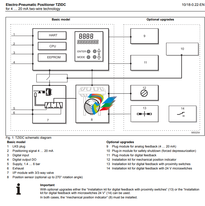
1 Description Pos: 3.2 /==== Wechsel ein- auf zweispaltig ==== @ 0mod_1130421847171_3101.doc @ 3828 Wechsel ein-auf zweispaltig Pos: 3.3 /Technische Daten / Datenblatt/Aktorik/Stellungsregler/Allgemein/Kurzbeschreibung/Kurzbeschreibung @ 10mod_1173180169769_3101.doc @ 71118 The TZIDC is an electronically configurable positioner with communication capabilities designed for mounting to pneumatic linear or rotary actuators. It features a small and compact design, a modular construction, and an excellent cost-performance ratio. Fully automatic determination of the control parameters and adaptation to the final control element yield considerable time savings and an optimal control behavior. Pos: 3.4 /Überschriften/1.1/2-spaltig/Pneumatik @ 10mod_1176211138453_3101.doc @ 76683 1.1 Pneumatics Pos: 3.5 /Technische Daten / Datenblatt/Aktorik/Stellungsregler/Allgemein/Kurzbeschreibung/Pneumatik @ 10mod_1173180645393_3101.doc @ 71139 a An I/P module with subsequent pneumatic amplifier is used to control the pneumatic actuator. The well-proven I/P module proportionally converts the permanent electrical positioning signal from the CPU into a pneumatic signal used to adjust a 3/3-way valve. The air flow for pressurizing or depressurizing the actuator is continuously adjusted. As a result, excellent control is achieved. When reaching the set point, the 3/3-way valve is closed in center position to minimize the air consumption. Four different pneumatics versions are available: for single-acting or double-acting actuators, each with “fail-safe” or “fail-freeze” function. Pos: 3.6 /Überschriften/1.1.1/2-spaltig/Sicherheitsfunktion "entlüftend" @ 10mod_1176211744343_3101.doc @ 76809 1.1.1 “Fail-safe” function Pos: 3.7 /Technische Daten / Datenblatt/Aktorik/Stellungsregler/Allgemein/Kurzbeschreibung/Sicherheitsfunktion "entlüftend" @ 10mod_1176211673796_3101.doc @ 76788 If the electrical power supply fails, the positioner output 1 is depressurized, and the pneumatic actuator’s return spring moves the valve to the defined safe position. In case of a double-acting actuator the second output 2 is additionally pressurized. Pos: 3.8 /======= Spaltenumbruch ======== @ 0mod_1132937966324_3101.doc @ 3831 Pos: 3.9 /Überschriften/1.1.1/2-spaltig/Sicherheitsfunktion "blockierend" @ 10mod_1176211798765_3101.doc @ 76830 1.1.2 “Fail-freeze” function Pos: 3.10 /Technische Daten / Datenblatt/Aktorik/Stellungsregler/Allgemein/Kurzbeschreibung/Sicherheitsfunktion "blockierend" @ 10mod_1176211845484_3101.doc @ 76851 If the electrical power supply should fail, the positioner output 1 (and 2, if applicable) is closed and the pneumatic actuator stops (“freezes”) the valve in the current position. If compressed air supply should fail, the positioner depressurizes the actuator. Pos: 3.11 /Überschriften/1.1/2-spaltig/Bedienung @ 10mod_1176211172234_3101.doc @ 76704 1.2 Operation Pos: 3.12 /Technische Daten / Datenblatt/Aktorik/Stellungsregler/Allgemein/Kurzbeschreibung/Bedienung (Kommunikationsmöglichkeit) @ 10mod_1173184631054_3101.doc @ 71160 The positioner has a built-in operating panel providing a 2-line LCD and 4 pushbuttons for optimal local configuration, commissioning and operational monitoring. Alternatively, the appropriate configuration program and the available communication option can be used. Pos: 3.13 /Überschriften/1.1/2-spaltig/Kommunikation @ 10mod_1176211201546_3101.doc @ 76725 1.3 Communication Pos: 3.14 /Technische Daten / Datenblatt/Aktorik/Stellungsregler/TZIDC / TZIDC-200/Kurzbeschreibung/Kommunikation @ 10mod_1176212225390_3101.doc @ 76893 The standard TZIDC model has a local communication interface (LKS connector). Additionally, a “HART communication” option for communication via the 20 mA signal is available. Both communications are based on the HART Protocol. Pos: 3.15 /Überschriften/1.1/2-spaltig/Ein-/Ausgänge @ 10mod_1176211233015_3101.doc @ 76746 1.4 Inputs and outputs Pos: 3.16 /Technische Daten / Datenblatt/Aktorik/Stellungsregler/TZIDC / TZIDC-200/Kurzbeschreibung/Ein-/Ausgänge @ 10mod_1176212290390_3101.doc @ 76914 In addition to its input for the analog position set point the TZIDC positioner is equipped with a digital input which can be used to activate various protective functions in the device via the process control system. A digital output allows you to output collective alarms or fault messages. Pos: 3.17 /Überschriften/1.1/2-spaltig/Modularer Aufbau @ 10mod_1176211317984_3101.doc @ 76767 1.5 Modular design Pos: 3.18 /Technische Daten / Datenblatt/Aktorik/Stellungsregler/Allgemein/Kurzbeschreibung/ModularerAufbau @ 10mod_1173184783043_3101.doc @ 71181 q The TZIDC basic model can be enhanced at any time by retrofitting optional equipment. Option modules for analog or digital position feedback or a shutdown-module can be installed. Additionally, a mechanical position indicator, proximity switches or 24 V microswitches are available for indicating the position independently of the mother board function.
2 Mounting versions Pos: 5.2 /==== Wechsel ein- auf zweispaltig ==== @ 0mod_1130421847171_3101.doc @ 3828 Wechsel ein-auf zweispaltig Pos: 5.3 /Überschriften/1.1/2-spaltig/Genormter Anbau an pneumatische Linearantriebe @ 10mod_1176212852312_3101.doc @ 76956 2.1 To linear actuators in accordance with the standard Pos: 5.4 /Technische Daten / Datenblatt/Aktorik/Stellungsregler/Allgemein/Montage/Genormter Anbau an pneumatische Linearantriebe @ 10mod_1176213091968_3101.doc @ 77040 Lateral attachment is in accordance with DIN / IEC 534 (lateral attachment to NAMUR). The required attachment kit is a complete set of attachment material, but does not include the screwed pipe connections and air pipes. Pos: 5.5 /Überschriften/1.1/2-spaltig/Genormter Anbau an pneumatische Schwenkantriebe @ 10mod_1176212899953_3101.doc @ 76977 2.2 To rotary actuators in accordance with the standard Pos: 5.6 /Technische Daten / Datenblatt/Aktorik/Stellungsregler/Allgemein/Montage/Genormter Anbau an pneumatische Schwenkantriebe @ 10mod_1176213146937_3101.doc @ 77061 This attachment is designed for mounting according to the standard VDI/VDE 3845. The attachment kit consists of a console with mounting screws for mounting on a rotary actuator. The adapter for coupling the positioner feedback shaft to the actuator shaft has to be ordered separately. Screwed pipe connections and air pipes have to be provided on site. Pos: 5.7 /======= Spaltenumbruch ======== @ 0mod_1132937966324_3101.doc @ 3831 Pos: 5.8 /Überschriften/1.1/2-spaltig/Integrierter Anbau an Regelventile @ 10mod_1176212940421_3101.doc @ 76998 2.3 Integral mounting to control valves Pos: 5.9 /Technische Daten / Datenblatt/Aktorik/Stellungsregler/Allgemein/Montage/Integrierter Anbau an Regelventile, TZIDC-1x0 @ 10mod_1176213402234_3101.doc @ 77103 The TZIDC positioner featuring standard pneumatic action is also suitable for integral mounting. The required holes are found at the back of the device. The benefit of this design is that the point for mechanical stroke measurement is protected and that the positioner and actuator are linked internally. No external tubing is required. Pos: 5.10 /Überschriften/1.1/2-spaltig/Besondere antriebsspezifische Anbauversionen @ 10mod_1176212991062_3101.doc @ 77019 2.4 Special actuator-specific mounting Pos: 5.11 /Technische Daten / Datenblatt/Aktorik/Stellungsregler/Allgemein/Montage/Besondere antriebsspezifische Anbauversionen @ 10mod_1173186727709_3101.doc @ 71265 In addition to the mounting methods described above, there are special actuator-specific attachments. Please contact us for details.
-
 Beckhoff C6640-0040 Control Cabinet Industrial PC 7-Slot
 -
 BECKHOFF CONTROL CABINET INDUSTRIAL PC - C6930-1062-0050
 -
 Beckhoff Automation EtherCAT Terminal EK1100 EK1122
 -
 Beckhoff CP6533-0001-0060 IPC
 -
 Beckhoff EK9500 | EtherNet/IP™ Bus Coupler
 -
 Beckhoff CP6202-1047-0050 - An industrial-grade embedded panel computer.
 -
 Beckhoff C6650-0040 Industrial PC
 -
 BECKHOFF CX5230-0185 / 000119805 PLC Module
 -
 BECKHOFF EL4732 | EtherCAT Terminal, 2-channel analog output, voltage, ±10 V, 16 bit, oversampling
 -
 Beckhoff CP6202-0001-0010 Economy Built-In Panel
 -
 Beckhoff AX5206-0000-0202 Digital Compact Servo Drives 2-channel
 -
 Beckhoff CP6606-0001-0020 7-inch Economy Panel PC
 -
 Beckhoff CPU basic module CX2020-0155 + power supply module CX2100-0004
 -
 Beckhoff CP2913-000 Multi-Touch Display
 -
 Beckhoff CP6500-1012-0060 14250369 Control Cabinet
 -
 Beckhoff CP7902-0001-0000 Economy Control Panel with DVI/USB Extended interface
 -
 Beckhoff C6920-0010 Control cabinet Industrial PC
 -
 BECKHOFF C3640-0050 Build-in Industrial PCs
 -
 Beckhoff KL6023-0000 KL6023 EnOcean Wireless-Adapter
 -
 Kollmorgen AKM54G-ANC2DB00 servo motor
 -
 Kollmorgen AKD-P00606-NBCN-0000 Servo Drive
 -
Kollmorgen S200 Series S20350-VTS SERVO DRIVE
-
 KOLLMORGEN AKD-P00606-NBCC-I000 SERVO DRIVE
 -
 Kollmorgen MV65WKS-CE310/22PB Servo Drive Control Module
 -
 Kollmorgen S20360-VTS-021 Servo Drive
 -
 KOLLMORGEN CR06550 High-precision digital servo amplifier
 -
 KOLLMORGEN DBL5N01050-03S-VV0-S40 3-Phase AC Synchronous Brushless Servo Motor
 -
 KOLLMORGEN S70301-NANANA-024 SERVO DRIVE
 -
 Kollmorgen S20360-VTS S200 Series Servo Drive
 -
 Kollmorgen RBE-03011-A00 Brushless Frameless Servo Motor
 -
 KOLLMORGEN AKD-T00306-NBAN-0000 INPUT SERVO DRIVE
 -
 KOLLMORGEN S700 Servo Controller S70302-NANANA
 -
 Kollmorgen AKD-P00607-NBEC-0000 400/480VAC 4.40KVA Servo Drive.
 -
 KOLLMORGEN S70102-NANANA SERVO DRIVE
 -
 KOLLMORGEN AKM21E-ANSNEH02 PM Servo Motor & PRD-AMPE25EB-00 Servo Drive Array
 -
 KollMorgen SC1R06260 Servo Drive 1.4/2.2 KVA 115230 Vac
 -
 Kollmorgen AKD-P00306-NBAN-0000 Servo Drive
 -
Kollmorgen TTB2-2042-3052-A DC Motor Industrial Drive 5.5A 185 oz/in
-
 KOLLMORGEN SERVOSTAR 610-AS SERVO AMPLIFIER_SERVOSTAR610AS_S61001
 -
 KOLLMORGEN PRD-0016400P-10 & PRD-0016600D-30 Axis Control System Modules
 -
KOLLMORGEN Seidel DBL5N01700-03S-000-S40 Servo Motor
-
 Hirschmann RS20-1600M2T1SDAEHH03.1.02 Rail Switch
 -
 Hirschmann BRS30-24TX Industrial Rail Switch
 -
 Hirschmann RSPM20-4T14T1EV9HHS999.9.99 Managed Ethernet Switch
 -
 Hirschmann BELDEN RS40-0009CCCCSDAPHH09.0.14 / RS400009CCCCSDAPHH09014
 -
Hirschmann RS40 Rail Switch RS40-0009CCCCSDAE
-
 Hirschmann BELDEN RS30-0802T1T1SDAP / RS300802T1T1SDAP Fully Managed Layer 2 Compact Rail Switch
 -
 Hirschmann BELDEN RS20-0800M2M2SDAUHH / RS200800M2M2SDAUHH
 -
 Hirschmann EAGLE30-04022O6TT999SCCY9HSE3F Industrial Firewall Router Switch
 -
 Hirschmann RS20-1600T1T1SDAEHH09.0.14 RS20 Rail Mount Ethernet Switch
 -
 Hirschmann EAGLE0200T1T1TDDY90000HHE05.3.03 Industrial Security Router
 -
Hirschmann - BELDEN MIPP-AD-1L9P
-
 HIRSCHMANN RSPM20-4Z64Z6TV9HHS9 942 106-999 RAIL SAFETY SWITCH
 -
 HIRSCHMANN FIBEROPTIC MODULE FIP P/N: OZDFIPG3T
 -
 HIRSCHMANN RS20-1600M2M2SDAUHH Ethernet rack-mounted switch
 -
 HIRSCHMANN BELDEN RS20-0400T1T1SDAEHH04.0.01 / RS200400T1T1SDAEHH04001
 -
HIRSCHMANN MM2-4FXM3 MICE Media Module
-
HIRSCHMANN RS20-0800M2M2SDAE Industrial Ethernet Rail Switch
-
 Hirschmann RS20-2400T1T1SDAP / RS20-2400T1T1SDAPHH05.0.02
 -
 GE MLJ1005B010H00C MLJ Digital Synchromism Check
 -
 ALSTOM MICROTECH DX21-M2 Digital Excitation Controller
 -
HIRSCHMANN BRS20-1200ZZZZ-STCY99HHSES
-
 HIRSCHMANN MM3-4FXM2 MICE Media Module
 -
Hirschmann RSB20-0800T1T1SAABHH 8Port ENet Rail Switch RSB20
-
 Hirschmann MACH102-8TP Ethernet Switch
 -
 SAACKE DDZ-M marine steam pressure atomizer
 -
 SAACKE SKV-A marine rotary cup atomizer
 -
 SAACKE Seavis HMI05e
 -
 Kollmorgen MMC-SD-2.0-230 Servo Drive 100-240VAC 2KW 10A Output 3PH 100-240VAC
 -
 Kollmorgen Servo drive CR10550
 -
 Kollmorgen AKD-P01207-NACN-0054 Servo Driver
 -
 Kollmorgen S406M-CA-036 Servostar
 -
.png) Kollmorgen AKD-B02407-NAAN-0000 Digital Servo Drive
Kollmorgen AKD-B02407-NAAN-0000 Digital Servo Drive -
 Kollmorgen SERVOSTAR S406AM-CA Digital Servo Drive
 -
 KOLLMORGEN SERVOSTAR 603-AS SERVO AMPLIFIER_SERVOSTAR603AS_S60301
 -
Kollmorgen S700 Servo Controller (S70602-NANANA-NA)
-
 Kollmorgen MPK411 controller
 -
 KOLLMORGEN MMC-SD-1.3-460-D Smart Drive
 -
 KOLLMORGEN AKM21C-CKB2AA-00 / AKM21CCKB2AA00 Servomotor
 -
 BECKHOFF AX5106-0000-0200 | Digital Compact Servo Drives 1-channel
 -
 BECKHOFF C3620-0000 INDUSTRIAL COMPUTER (MOTORSHELVES)
 -
 Beckhoff EK1960-0000 TwinSAFE Compact Controller
 -
 Beckhoff C6930-0050 Control Cabinet Industrial PC
 -
 Beckhoff CP7711-0001-0030 Industrial Computer Detection
 -
 Beckhoff CX1001-0111 Embedded PC CPU Module
 -
 Beckhoff C6017-0020 | Ultra-compact Industrial PC
 -
 Beckhoff EK1322 | 2-port EtherCAT P junction with feed-in
 -
 Beckhoff CP2219-0010 Panel
 -
 BECKHOFF C6015-0020 ULTRA COMPACT INDUSTRIAL PC
 -
 BECKHOFF CX2030-0120/Standard CPU Module Embedded PC Windows PLC controller
 -
 Beckhoff CP7721-1090-0020 Panel PC
 -
 Beckhoff PC CPU Module CX5130-0175
 -
 Beckhoff C6920-0050 Control Cabinet
 -
 Beckhoff EL6631 EtherCAT 2-Port Communication Interface, Profinet RT Controller
 -
 Beckhoff CP6202-0001-0060 touch screen panel PC
 -
 Beckhoff CP3916-1002-0000 Multi-Touch Control Panel
 -
 Beckhoff EP1809-0021 | EtherCAT Box, 16-channel digital input, 24 V DC, 3 ms, M8Preferred type
 -
 Beckhoff CX8190 PLC Embedded Industrial PC Ethernet Controller
 -
 Beckhoff CX2100-0914 Power Supply for External
 -
 Beckhoff Automation CP6906-0001-0000 HMI
 -
 Beckhoff EP7342-0002 Module
 -
 Beckhoff CX1020-0112 / CX1100-0910 / CX1020-N010 / CX1100-0003 Windows CPU
 -
 Beckhoff EP7211-0034 EtherCAT Box 1 Channel Motion Interface
 -
 Beckhoff C6240-0030 Control cabinet Industrial PC
 -
 beckhoff motherboard CB1052-0004 CB1052-0004
 -
 Beckhoff AX2006-AS Servo Drive / Variable Frequency Drive
 -
BECKHOFF CP6207-0001-0020 NSMP
-
 Beckhoff C6930-1142-0060 Industrial Computer
 -
 Beckhoff FC7501-0000 interface card
 -
 Beckhoff CX5140-0175 Embedded PC PLC CPU CX5140 Industrial Controller
 -
 Beckhoff CP7802-1100-0010: High-End IP65 Control Panel with DVI/USB Extended Interface
 -
BECKHOFF CP3716-1058-0010 CONTROL PANEL
-
 Beckhoff AX8108-0000 Single-Axis Module
 -
 Beckhoff CU8851-0000 | USB extension, USB Extended 2.0 receiver box
 -
Beckhoff C6017-0030 | Ultra-compact Industrial PC
-
 Beckhoff CX1001-0120/CX10010120.cx1000-n001.cx1000-n000 System Overview
 -
 Beckhoff CPU Module CX5140-0155/4GB CPU Module
 -
 Beckhoff CP6533-0001-005: Built-in Panel PC with High-Definition Multi-Touch Control
 -
 Beckhoff EL5042 | EtherCAT Terminal, 2-channel encoder interface, BiSS® C
 -
 Beckhoff C6920-1080-0040: Premium Control Cabinet Industrial PC
 -
 Beckhoff C6920-0060 | Control cabinet Industrial PC
 -
 Beckhoff Embedded-PC CX5010-1121
 -
 Beckhoff CB3050-0010 Mainboard Motherboard
 -
 Beckhoff PLC module CX1020-0000 Basic CPU module (service phase)
 -
 Beckhoff CP7812-1056-0010 15" Multitouch Display Control Panel
 -
 Beckhoff CX5120-0115 /2GB Controller Module
 -
 Beckhoff CP7201-1000-0000 Industrial Panel PC
 -
 Beckhoff Servo Motor AM8061-0JH1-0000


