
EMERSONDeltaV™ Electronic Marshalling for Migrations
DeltaV™ Electronic Marshalling for Migrations
I/O anywhere you need it
Single channel granularity
Replaces legacy I/O in place
Fully redundant architecture
Complete DeltaV™ solution
Plug and play I/O
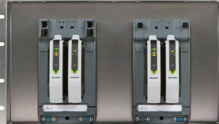
DeltaV™ CHARM I/O Cards (CIOC) mounted on a Migration Panel.
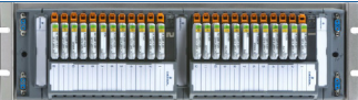
DeltaV CHARM I/O Baseplate Migration Panel.
Introduction
DeltaV™ Electronic Marshalling delivers a new level of control
system I/O performance with unprecedented flexibility and
ease of use. The CHARM I/O card (CIOC) supports up to
96 individually configurable channels and when mounted
horizontally in conjunction with a legacy system migration
will allow for direct replacement of legacy hardware within
existing cabinets. Now you can migrate to DeltaV without
having to add cabinets, custom cables, or extra marshalling.
All communications are completely redundant from the
channel (CHARM) to the DeltaV controller.
Benefits
I/O anywhere you need it: The DeltaV CIOC provides
unprecedented flexibility in control system I/O topology.
Now you can mount your DeltaV I/O in the same space as your
legacy I/O for a direct 1-to-1 replacement. Without adding
any new cabinets of DeltaV hardware you can replace all your
legacy equipment leaving behind a complete DeltaV solution.
Single Channel granularity: The CHARM I/O architecture
allows each individual channel to be characterized for the
requirements of the field device. Any instrument signal can be
wired to any terminal block. The channel is then electronically
marshalled by installing the appropriate CHARM and assigning
the channel to one of four controllers. Legacy I/O terminations
are no longer a concern because of multiple channel types
from a single termination panel. Just install the proper CHARM
to characterize the I/O as found on the legacy panels. No more
engineering and splitting signals from a single legacy panel to
multiple DeltaV I/O cards.
Replaces legacy I/O in place: DeltaV Electronic Marshalling
goes where no one else’s I/O can. Install the CHARMs migration
panel above, below, or even in front of your legacy termination
panel and move your wires inches to complete your migration
to DeltaV. Since the CHARMs migration panel is a standard
CHARMs baseplate, it talks to the CIOC the same as the
standard vertical installation through the cable interface.
This allows you to mount the migration panel in the best
location to facilitate a clean system cutover and not have to
“stretch” your I/O cables to a new termination. As an added
bonus, install CHARMs vertical if your wiring allows for it in
certain areas. Now you can mount your I/O in any orientation
as best fits your current migration layout and needs.
Fully redundant communications: The CIOC architecture is
fully redundant. This starts with the two I/O cards on a carrier.
The carrier has redundant communication modules for primary
and secondary network connections. There are two 24 V DC
input power connections. The carrier connects to the CHARMs
Baseplates and provides redundant power and communication
buses to the CHARMs. Everything is redundant down to the
individual channel.
Complete DeltaV solution: Migrate from your legacy system
with the comfort that when complete you will have a complete
DeltaV solution, not a combination of standard and custom
hardware/software to support. Every piece of the migration
panel is standard DeltaV hardware and can be supported with
the same personnel and spare equipment that every other
CHARMs and DeltaV installation uses.
Plug and play I/O: The DeltaV CIOC has been designed for
ease of use, both in physical installation and its software tools.
Components snap together with secure DIN-rail latches and
interlocking carrier connectors. Insert the CHARMs and auto
sense the node to create the I/O definition automatically in
your DeltaV configuration database. CHARMs use a self-keying
system to automatically set a channel for a specific CHARM
type. Users cannot mistakenly insert a CHARM into the wrong
terminal block. Assign all, one, or any number of channels to a
controller with a simple click and drag.
CHARM and Terminal Block.
Field power is provided through a redundant 24V DC bus to
each CHARM, with up to 100 mA per CHARM. Higher current
Discrete Channels can be powered through integrated power
injection bus local to each CHARM Baseplate.
Product Description
Electronic Marshalling for Migrations hardware includes:
CHARM I/O Carrier (DIN-rail mounted and supports
redundant pair of CHARM I/O Cards).
CHARM I/O Card (CIOC) provides communication between
CHARMs and the Ethernet I/O network to M-series, S-series,
and PK controllers. The CIOC has Achilles Communications
Certification Level 1 and the redesigned CIOC2 has more
computing power and Achilles Communications Certification
Level 2. The CIOC2 is a drop-in replacement for the CIOC.
CHARM Baseplate (DIN-rail mounted with interleaving power
and bus connectors. Supports 12 CHARMs and their terminal
blocks, as well as connection for injected field power).
CHARM Terminal Block (removable terminal block
providing terminal connections to field wiring and
physical latch for CHARM).
CHARMs (Characterization Module for each field signal.
Provides basic analog to digital conversion, connectivity
to redundant communication bus, and fault isolation)
Replaces legacy I/O in place: DeltaV Electronic Marshalling
goes where no one else’s I/O can. Install the CHARMs migration
panel above, below, or even in front of your legacy termination
panel and move your wires inches to complete your migration
to DeltaV. Since the CHARMs migration panel is a standard
CHARMs baseplate, it talks to the CIOC the same as the
standard vertical installation through the cable interface.
This allows you to mount the migration panel in the best
location to facilitate a clean system cutover and not have to
“stretch” your I/O cables to a new termination. As an added
bonus, install CHARMs vertical if your wiring allows for it in
certain areas. Now you can mount your I/O in any orientation
as best fits your current migration layout and needs.
Fully redundant communications: The CIOC architecture is
fully redundant. This starts with the two I/O cards on a carrier.
The carrier has redundant communication modules for primary
and secondary network connections. There are two 24 V DC
input power connections. The carrier connects to the CHARMs
Baseplates and provides redundant power and communication
buses to the CHARMs. Everything is redundant down to the
individual channel.
Complete DeltaV solution: Migrate from your legacy system
with the comfort that when complete you will have a complete
DeltaV solution, not a combination of standard and custom
hardware/software to support. Every piece of the migration
panel is standard DeltaV hardware and can be supported with
the same personnel and spare equipment that every other
CHARMs and DeltaV installation uses.
Plug and play I/O: The DeltaV CIOC has been designed for
ease of use, both in physical installation and its software tools.
Components snap together with secure DIN-rail latches and
interlocking carrier connectors. Insert the CHARMs and auto
sense the node to create the I/O definition automatically in
your DeltaV configuration database. CHARMs use a self-keying
system to automatically set a channel for a specific CHARM
type. Users cannot mistakenly insert a CHARM into the wrong
terminal block. Assign all, one, or any number of channels to a
controller with a simple click and drag.
CHARM and Terminal Block.
Field power is provided through a redundant 24V DC bus to
each CHARM, with up to 100 mA per CHARM. Higher current
Discrete Channels can be powered through integrated power
injection bus local to each CHARM Baseplate.
Product Description
Electronic Marshalling for Migrations hardware includes:
CHARM I/O Carrier (DIN-rail mounted and supports
redundant pair of CHARM I/O Cards).
CHARM I/O Card (CIOC) provides communication between
CHARMs and the Ethernet I/O network to M-series, S-series,
and PK controllers. The CIOC has Achilles Communications
Certification Level 1 and the redesigned CIOC2 has more
computing power and Achilles Communications Certification
Level 2. The CIOC2 is a drop-in replacement for the CIOC.
CHARM Baseplate (DIN-rail mounted with interleaving power
and bus connectors. Supports 12 CHARMs and their terminal
blocks, as well as connection for injected field power).
CHARM Terminal Block (removable terminal block
providing terminal connections to field wiring and
physical latch for CHARM).
CHARMs (Characterization Module for each field signal.
Provides basic analog to digital conversion, connectivity
to redundant communication bus, and fault isolation)
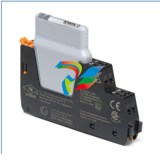
Cable Extenders that provide flexibility in carrier mounting.
Baseplate terminators (provides bus terminations for
redundant I/O bus).
19” Migration Panels (provides DIN-rail mounting for two
migration CIOC’s or two baseplates and cable extenders
for installation into your standard 19” legacy cabinets).
CIOC Migration Panel
The CHARM I/O card carrier is supposed to be mounted
on a vertical DIN-rail and can communicate with up to
eight CHARM Baseplates mounted vertically or on migration
panels and connected to each other through extender cables.
The bus terminators are attached to the last baseplate.
Baseplate Migration Panel
Each CHARMs Migration Baseplate Assembly is
ordered pre-loaded with 24 terminal blocks that are
ready to receive field wires from 2-, 3- , and 4-wire devices.
Electronic Marshalling eliminates the need to scramble the
field wiring or to partition the I/O to match signals to channel
types of specific cards. Simply connect field signals in an orderly
fashion as desired. Insert the appropriate CHARM into each
terminal block to complete the field circuit and the signal
is ready to be used by any, up to four controllers.
For each Migration CIOC installation you will need to
determine the quantity and connector cable length as
well as the appropriate quantity of top and/or bottom
baseplate terminators.
The Migration CIOC assembly has a height of 6 EIA units
(10.5 inches) and is designed to be mounted at the top
of the migration cabinet and connected to the CHARM
baseplate assemblies through the cables and cable extenders.
It should be noted that the CIOC can be mounted on vertical
DIN-rail anywhere in the cabinet (front, back, side, top,
middle, bottom) and connected to the CHARM baseplate
assembly the same way. NOTE: the CIOC cannot be mounted
on a horizontal DIN-rail.
The Migration CHARM baseplate assembly has a height of
3 EIA units (5.25 inches) which allows for each installation
to determine the mounting location within each cabinet.
The user can decide to reuse existing wire way / cable tray,
mount each assembly adjacent to each other, or mount with
spacing between each assembly. DeltaV CHARMs allow for
installation flexibility by allowing each assembly to be mounted
as needed to achieve the best result for each customer-specific
termination installation.
Each CHARM acts as a circuit protection device and field wiring
disconnects. Signals are current limited or fused to protect
against wiring faults to ground. Each CHARM provides surge
protection to meet industry standards in the area of EMC, and is
designed to fail during overvoltage conditions due to incorrect
field wiring. Signal faults are isolated to the single CHARM.
CHARMs can be partially ejected to a locked position that
disconnects the field wiring from the system to perform field
maintenance actions or to remove power to a field device.
Activating the CHARM latch ejects the CHARM to the detent
position. Closing the latch locks the CHARM in place and
isolates the field wiring for field work.
The CIOC communicates over Ethernet with up to four
controllers, allowing great flexibility and ease of system
expansion. Additional controllers can be added to
accommodate increased control scope and I/O can be
reassigned without changing the physical wiring. This allows
you the flexibility required in migrations where over time
I/O has been landed on one controller only to be used in
another because of space and or available I/O.
CHARM Types
All CHARM types function on the migration panel. See DeltaV
Electronic Marshalling PDS and DeltaV IS Electronic Marshalling
PDS for a complete listing of CHARMs and IS CHARMs.
I/O Terminal Block Options
All IS and non IS I/O Terminal Block types function on the
migration panel by choosing the right baseplate assembly.
CHARM Keying Posts
Keying Posts function the same.
CHARM I/O Card Hardware
See DeltaV Electronic Marshalling PDS and DeltaV IS Electronic
Marshalling for a complete description of CIOC Hardware.
CHARM I/O Card Carrier
See DeltaV Electronic Marshalling PDS and DeltaV IS
Electronic Marshalling PDS for a complete description
of CIOC Carrier Hardware.
Hardware Specifications
CHARM I/O Migration Panel
Environmental Specifications
Operating Temperature* -40 to 70°C (-40 to 158°F)**
Storage Temperature -40 to 85°C (-40 to 185°F)
Relative Humidity 5 to 95% , non-condensing
Protection Rating IP 20
Airborne Contaminants ISA-S71.04-1985 Airborne Contaminants Class G3
Conformal coating
Shock 10 g ½-sine wave for 11 ms
Vibration 1 mm peak-to-peak from 5 to 13.2 Hz;
0.7 g from 13.2 to 150 Hz
Dimensions
Height 10.5 in (26.7 cm)
Depth 6.68 in (17.4 cm)
Width 19 in (48.3 cm)
Mounting 19 in (48.3 cm) EIA rails
6 Rack Units (U) high
-
 AEROTECH SM Series High-Performance Stepper Motors
 -
 AEROTECH BLMSC Series Linear Motors
 -
 AEROTECH Custom Linear Motors
 -
 AEROTECH BMS Series Brushless, Slotless Rotary Motors
 -
 AEROTECH BM Series Brushless Rotary Motors
 -
 AEROTECH BLMX Series Linear Motors
 -
 AEROTECH BLMH Series Linear Motors
 -
 AEROTECH BLM Series Linear Motors
 -
 AEROTECH BLMC Series Linear Motors
 -
 AEROTECH BLMUC-143 Linear motor forcer with thermistor
 -
AEROTECH BLMUC-111 Linear motor forcer with thermistor
-
AEROTECH BLMUC-95 Linear motor forcer with thermistor
-
AEROTECH BLMUC-79 Linear motor forcer with thermistor
-
AEROTECH BLMUC Series Linear Motors
-
 AEROTECH Automation1 FLEX Distributed Amplifier Multi-Axis Servo Control System
 -
 AEROTECH Automation1 HXA4 6-Axis Hexapod Servo Drive
 -
 AEROTECH Automation1 iHXA4 6-Axis Hexapod Servo Drive with Motion Controller
 -
 AEROTECH Modular System Control Console
 -
 AEROTECH TV Series Transformers
 -
 AEROTECH TM Series Transformers
 -
 AEROTECH UFM Noise Filter Module
 -
 AEROTECH MFM Motor Filter Module
 -
 AEROTECH MPG Handwheel Pendant
 -
 AEROTECH Automation1 Multi-Axis Joystick
 -
 AEROTECH ETM Enhanced Throughput Module
 -
 AEROTECH Automation1 XL4s High-Speed, Single-Phase Linear Servo Drive
 -
 AEROTECH Automation1 XL2e Enhanced, Compact Linear Servo Drive
 -
 Automation1 iXL2e Enhanced, Compact Linear Servo Drive with Motion Controller
 -
 AEROTECH Automation1 XL5e Enhanced, Linear Servo Drive
 -
 AEROTECH Automation1 iXL5e Enhanced Linear Servo Drive with Motion Controller
 -
 AEROTECH Automation1 GI4 Laser Scan Head Controller
 -
 AEROTECH Automation1 SI4 Stepper Interface
 -
AEROTECH Automation1 XI4 Servo Interface
-
 AEROTECH AEROTECH Automation1 iXI4 Servo Interface with Motion Controller
 -
 AEROTECH Automation1 XC6e Enhanced, High-Power PWM Servo Drive
 -
 AEROTECH Automation1 iXC6e Enhanced, High-Power PWM Servo Drive with Motion Controller
 -
 AEROTECH Automation1 XC2 Compact PWM Servo Drive
 -
 AEROTECH Automation1 XC4 PWM Servo Drive
 -
 AEROTECH Automation1 GL4 Galvo Laser Scan Head Linear Drive
 -
 AEROTECH Automation1 XC2e Enhanced, Compact Servo Drive with PWM+
 -
 AEROTECH Automation1 XC4e Enhanced, PWM Servo Drive
 -
 AEROTECH Automation1 XR3 Multi-Axis Servo Drive Rack
 -
 AEROTECH Automation1 iXR3 Multi-Axis Servo Drive Rack with Motion Controller
 -
 AEROTECH Automation1 iXC2 Compact PWM Servo Drive with Motion Controller
 -
 AEROTECH Automation1 iXC2e Enhanced, Compact PWM+ Servo Drive with Motion Controller
 -
 AEROTECH Automation1 iXC4 PWM Servo Drive with Motion Controller
 -
 AEROTECH Automation1 iXC4e Enhanced, PWM Servo Drive with Motion Controller
 -
 AEROTECH Automation1 iPC Industrial PC with Motion Controller
 -
 AEROTECH EPICS & TANGO Drivers for Distributed Control Systems
 -
 AEROTECH .NET, C, Python & LabVIEW APIs Custom Application Develotpmen
 -
 AEROTECH Automation1 Industrial Ethernet Support
 -
 AEROTECH Automation1 iSMC Intelligent, Software-Based Motion Controller
 -
 AEROTECH Automation1 iXA4 1- 2- or 4-Axis PWM Servo Drive with Motion Controller
 -
 AEROTECH Automation1 XA4 1- 2- or 4-Axis PWM Servo Drive
 -
 CTI 2500-ADP2-DISC Discrete Wiring Adapter for Series 500
 -
 CTI 2500-ADP1 Analog Wiring Adapter for Series 500
 -
 CTI 2500C-RADP-RS485 Remote Base Controller Adapter for Series 500
 -
 CTI 2500C-RADP-RBC Profibus RBC Adapter for Series 500
 -
 CTI 2500C-PADP-120V 120VAC 50W Power Supply for Series 500
 -
 CTI 2500-RADP RBC Adapter for Series 500
 -
 CTI 2500-R4500 520/530/DBC Adapter for Series 500 - MATURE
 -
 CTI 2500-PADP Power Supply Adapter for Series 500
 -
 CTI 2500-IADP I/O Adapter for Series 500
 -
 CTI 2500-VP15A-N4-W7 15" Flat-Panel PC with Windows® 7 Embedded
 -
 CTI 2500S-27-1750 Slice I/O, Ethernet, RS232/485. 900MHz, 2DIO / 4UAI / 2AI
 -
 CTI 2500S-26-1750 Slice I/O, Ethernet, RS232/485. 900MHz, 8DIO / 2UAI
 -
 CTI 2500S-23-1750 Slice I/O, Ethernet, RS232/485. 900MHz, 4DI / 4DO / 2UAI / 2AO
 -
 CTI 2500S-27-1550 Slice I/O, RS232/485. 2DIO / 4UAI / 2AI
 -
 CTI 2500S-26-1550 Slice I/O, RS232/485. 8DIO / 2UAI
 -
 CTI 2500S-23-1550 Slice I/O, RS232/485. 4DI / 4DO / 2UAI / 2AO
 -
 CTI 2500S-27-1050 Slice I/O, Ethernet, 2DIO / 4UAI / 2AI
 -
 CTI 2500S-26-1050 Slice I/O, Ethernet, 8DIO / 2UAI
 -
 CTI 2500S-23-1050 Slice I/O, Ethernet, 4DI / 4DO / 2UAI / 2AO
 -
 CTI 2500C-32F-CJC 32-Pin Field Wiring Connector with Cold Junction Compensation
 -
 CTI 2500C-32F 32-Pin Field Wiring Connector
 -
 CTI 2500C-8-TC Eight Thermocouple Inputs
 -
 CTI 2500C-8-RTD Eight RTD Inputs
 -
 CTI 2500C-8-RL-FC 8 Form-C Relay Outputs
 -
 CTI 2500C-8-IDO-24V 8 Isolated 24VDC Outputs
 -
 CTI 2500C-8-IDO-120V 8 Isolated 120VAC Outputs
 -
 CTI 2500C-16-DO-24V Sixteen 24VDC Digital Outputs
 -
 CTI 2500C-16-DO-120V Sixteen 120VAC Digital Outputs
 -
.png) CTI 500C-16-IDI-24V Sixteen Isolated 24V AC/DC Digital Inputs
CTI 500C-16-IDI-24V Sixteen Isolated 24V AC/DC Digital Inputs -
 CTI 2500C-16-IDI-120V Sixteen Isolated 120V AC/DC Digital Inputs
 -
 CTI 2500C-16-DIDO-SIM Sixteen Digital Input and Output SImulator
 -
 CTI 2500C-16-DI-24V Sixteen 24V AC/DC Digital Inputs
 -
 CTI 2500C-16-DI-120V Sixteen 120V AC/DC Digital Inputs
 -
 CTI 2500C-RBC-RS485 RS485 Remote Base Controller
 -
 CTI 2500C-RBC-PRF Profibus Remote Base Controller
 -
 CTI 2500C-PS-24V-35 35-Watt DC Power Supply
 -
 CTI 2500C-PS-120V-35 35-Watt AC Power Supply
 -
 CTI 2500C-R8 Eight-Slot Base
 -
 CTI 2500C-R4 Four-Slot Base
 -
 CTI 2500C-R16 Sixteen-Slot Base
 -
 CTI 2500C-2572-B Fast Ethernet TCP/IP Adapter
 -
 CTI 2500C-J750 Compact Janus PAC with 3MB Project Memory
 -
 CTI 2500C-C300 CPU with 512K User Memory
 -
 CTI 2500C-C200 CPU with 256K User Memory
 -
 CTI 2500C-C100 CPU with 128K User Memory
 -
 CTI 2500C-8-AO 8 Analog Outputs
 -
 CTI 2500C-8-AI 8 Analog Inputs
 -
 CTI 2559-FCAL Precision Calibration Connector
 -
 CTI 2559-FPC 40-Position Screw-Terminal Connector
 -
 CTI 2500-RFC PLC to RF Modem Cable
 -
 CTI 2500-40F 40-Position Standard Screw-Terminal Connector
 -
 CTI 2505 Vibration Sensor Interface Module
 -
 CTI 2554-A 4-Channel Isolated High Speed Counter Module
 -
 CTI 2553-A 2-Channel Mag Meter Input Module
 -
 CTI 2502 2-Channel High Speed Counter Input Module
 -
 CTI 2559-TC 8-Channel Thermocouple Input Module
 -
 CTI 2556-A 16-Channel Isolated Thermocouple Input Module
 -
 CTI 2556 16-Channel Isolated Thermocouple Input Module
 -
 CTI 2551-A 8-Channel Isolated Thermocouple Input Module
 -
 CTI 2559-RTD 8-Channel RTD Input Module
 -
 CTI 2557-A 16-Channel RTD Input Module
 -
 CTI 2557 16-Channel RTD Input Module
 -
 CTI 2552-A 8-Channel Isolated RTD Input Module
 -
 CTI 2534 8-Point Form-C Relay Output Module
 -
 CTI 2532 16-Point Form-A Relay Output Module
 -
 CTI 2531 32-Point Form-A Relay Output Module
 -
 CTI 2530 8-Point Form-C Relay Output Module
 -
 CTI 2562 8-Channel Analog Output Module
 -
 CTI 2560-A 8-Channel Isolated Analog Output Module
 -
 CTI 2501 8in/4out Analog Module
 -
 CTI 2558 8-Channel Analog Input Module
 -
 CTI 2555-A 16-Channel Analog Input Module
 -
 CTI 2550-A 8-Channel Isolated Analog Input Module
 -
 CTI 2599 8/16/32-Point AC Output Module


