
Schneider ATV61
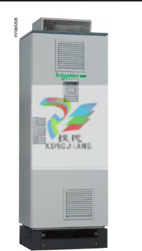
The Schneider ATV61 frequency converter has the following benefits: Performance advantage - high efficiency and energy saving: It adopts an efficient motor control strategy, optimizes energy consumption, reduces operating costs, and achieves a significant energy-saving ratio. Precise control: Equipped with multiple motor control modes, it achieves precise speed and torque control, enhancing system operational efficiency. Strong adaptability: With a wide power range and diverse voltage levels, it meets the needs of different application scenarios. Rich in functions and diverse integration options: It can be integrated into electrical installations, control systems and building management systems to achieve intelligent management. Complete protection functions: It features thermal protection for the motor and frequency converter, overload protection, underload protection, etc., ensuring the safe operation of the equipment. User-friendly interface: It provides a Chinese operation panel, with simple configuration, easy adjustment and maintenance. High reliability and robust design: It features a high protection level, can adapt to harsh environments, and is equipped with an EMC filter to reduce electromagnetic interference. Good stability: It adopts a wet multi-plate clutch, which is durable and stable, achieving flexible connection and absorbing shock. Widely applied in various industries: Suitable for industrial, construction, infrastructure and other fields, such as pumps, fans, HVAC, etc. Customization: It can be customized according to requirements to meet specific application needs. In conclusion, Schneider's ATV61 frequency converter, with its advantages of high efficiency and energy conservation, precise control, rich functions, high reliability and wide application, has become an ideal choice in the industrial and construction fields.
The main parameters of Schneider ATV61 frequency converter are as follows: Power supply and power voltage range: three-phase 200240V, 380480V, 500~690V. Power range: 0.75 to 630kW. Performance and control speed range: 1:100 in open-loop mode. Overload capacity: 110% to 120%, lasting for 60 seconds. Control mode: Supports sensorless voltage vector control and traditional V/F (2-point or 5-point) control. Speed regulation accuracy: ±10% of the motor's rated slip frequency in an open loop. Functions and Features: Energy-saving function: It has an energy-saving operation mode to optimize energy consumption. Protection functions: Thermal protection for motors and frequency converters, overload and overcurrent protection, mechanical protection, etc. Safety features: Integrated "power-off" function, in compliance with EN 954-1 Class 3 and IEC/EN 61508 SIL2 standards. Communication function: Built-in Modbus and CANopen protocols, supporting multiple expansion communication cards. I/O configuration: 6 logic inputs, 2 relay outputs, 2 analog inputs, 1 analog output, expandable. Environmental and certification operating temperature: -10℃ to 50℃ (up to 60℃ upon capacity reduction). Certification standards: Comply with international standards and certifications such as CE, UL, CSA, and C-Tick. These parameters demonstrate the wide applicability and high efficiency of the ATV61 frequency converter in industrial and construction applications.
The following is the usage method of Schneider ATV61 frequency converter: Preparatory work - insulation test: Disconnect the connection cable between the power supply terminal (R.S.T) and the motor terminal (U.V.W) of the frequency converter. Use a 500 megohm or 1000 megohm megohmmeter to check the insulation of the cable. If it meets the requirements, restore the wiring. Check the wiring: Verify the internal and external control circuit wiring of the frequency converter. Only after ensuring there are no errors can power be supplied. Before debugging, prepare to install the panel and select the language: Install the panel randomly brought, power on, select the language type (such as Chinese) and click OK. Record the motor nameplate information: Record the motor's power, voltage, frequency, rotational speed and rated current, etc. To set the parameters, enter the motor control menu: Input the motor nameplate information in the 1.4 Motor Control menu. Self-tuning: Perform self-tuning. Pay attention to supervising the motor on site to avoid misoperation. If the motor is found to be reversing, the output phase sequence needs to be changed. Set the acceleration time and deceleration time: In the 1.3 menu, set the acceleration time and deceleration time to the desired values, and set the low frequency and high frequency. Set input and output parameters: In the 1.5 menu, set the input and output parameters, such as 2/3 line control, AO1 allocation, AO1 type, AI2 setting, etc. Set command menu: Set Channel 1 to AI2, and set the combination mode to combination channel. For a given 2 switch, set it to LI5; for a given 2 channel, set it to LI acceleration and deceleration. Set the application menu: Switching to Channel 1 is effective when 1B is given, changing to no setting when 1B is given, and setting the acceleration allocation, deceleration allocation and parking mode. Set fault management: Set fault reset to not set, and set under-voltage fault voltage to 190V. Monitoring and adjusting monitoring parameters: During the operation of the motor, enter the 1.2 monitoring menu to observe various parameters, such as current, voltage, signal input and output, etc. Channel limitation: Please note that there is only one channel at the AO point of the frequency converter. The frequency and current of the motor can only be output to the site once. Make changes according to the specific situation. Set mode switching: When the frequency converter is adjusting the speed, only one set mode is supported. Switching between two set modes is required. Generally, a local remote knob dry contact is connected in series between the 24V and LI5 terminals. The above steps are for reference only. For specific operations, please refer to the user manual of Schneider ATV61 frequency converter in combination with the actual situation.
-
 AEROTECH SM Series High-Performance Stepper Motors
 -
 AEROTECH BLMSC Series Linear Motors
 -
 AEROTECH Custom Linear Motors
 -
 AEROTECH BMS Series Brushless, Slotless Rotary Motors
 -
 AEROTECH BM Series Brushless Rotary Motors
 -
 AEROTECH BLMX Series Linear Motors
 -
 AEROTECH BLMH Series Linear Motors
 -
 AEROTECH BLM Series Linear Motors
 -
 AEROTECH BLMC Series Linear Motors
 -
 AEROTECH BLMUC-143 Linear motor forcer with thermistor
 -
AEROTECH BLMUC-111 Linear motor forcer with thermistor
-
AEROTECH BLMUC-95 Linear motor forcer with thermistor
-
AEROTECH BLMUC-79 Linear motor forcer with thermistor
-
AEROTECH BLMUC Series Linear Motors
-
 AEROTECH Automation1 FLEX Distributed Amplifier Multi-Axis Servo Control System
 -
 AEROTECH Automation1 HXA4 6-Axis Hexapod Servo Drive
 -
 AEROTECH Automation1 iHXA4 6-Axis Hexapod Servo Drive with Motion Controller
 -
 AEROTECH Modular System Control Console
 -
 AEROTECH TV Series Transformers
 -
 AEROTECH TM Series Transformers
 -
 AEROTECH UFM Noise Filter Module
 -
 AEROTECH MFM Motor Filter Module
 -
 AEROTECH MPG Handwheel Pendant
 -
 AEROTECH Automation1 Multi-Axis Joystick
 -
 AEROTECH ETM Enhanced Throughput Module
 -
 AEROTECH Automation1 XL4s High-Speed, Single-Phase Linear Servo Drive
 -
 AEROTECH Automation1 XL2e Enhanced, Compact Linear Servo Drive
 -
 Automation1 iXL2e Enhanced, Compact Linear Servo Drive with Motion Controller
 -
 AEROTECH Automation1 XL5e Enhanced, Linear Servo Drive
 -
 AEROTECH Automation1 iXL5e Enhanced Linear Servo Drive with Motion Controller
 -
 AEROTECH Automation1 GI4 Laser Scan Head Controller
 -
 AEROTECH Automation1 SI4 Stepper Interface
 -
AEROTECH Automation1 XI4 Servo Interface
-
 AEROTECH AEROTECH Automation1 iXI4 Servo Interface with Motion Controller
 -
 AEROTECH Automation1 XC6e Enhanced, High-Power PWM Servo Drive
 -
 AEROTECH Automation1 iXC6e Enhanced, High-Power PWM Servo Drive with Motion Controller
 -
 AEROTECH Automation1 XC2 Compact PWM Servo Drive
 -
 AEROTECH Automation1 XC4 PWM Servo Drive
 -
 AEROTECH Automation1 GL4 Galvo Laser Scan Head Linear Drive
 -
 AEROTECH Automation1 XC2e Enhanced, Compact Servo Drive with PWM+
 -
 AEROTECH Automation1 XC4e Enhanced, PWM Servo Drive
 -
 AEROTECH Automation1 XR3 Multi-Axis Servo Drive Rack
 -
 AEROTECH Automation1 iXR3 Multi-Axis Servo Drive Rack with Motion Controller
 -
 AEROTECH Automation1 iXC2 Compact PWM Servo Drive with Motion Controller
 -
 AEROTECH Automation1 iXC2e Enhanced, Compact PWM+ Servo Drive with Motion Controller
 -
 AEROTECH Automation1 iXC4 PWM Servo Drive with Motion Controller
 -
 AEROTECH Automation1 iXC4e Enhanced, PWM Servo Drive with Motion Controller
 -
 AEROTECH Automation1 iPC Industrial PC with Motion Controller
 -
 AEROTECH EPICS & TANGO Drivers for Distributed Control Systems
 -
 AEROTECH .NET, C, Python & LabVIEW APIs Custom Application Develotpmen
 -
 AEROTECH Automation1 Industrial Ethernet Support
 -
 AEROTECH Automation1 iSMC Intelligent, Software-Based Motion Controller
 -
 AEROTECH Automation1 iXA4 1- 2- or 4-Axis PWM Servo Drive with Motion Controller
 -
 AEROTECH Automation1 XA4 1- 2- or 4-Axis PWM Servo Drive
 -
 CTI 2500-ADP2-DISC Discrete Wiring Adapter for Series 500
 -
 CTI 2500-ADP1 Analog Wiring Adapter for Series 500
 -
 CTI 2500C-RADP-RS485 Remote Base Controller Adapter for Series 500
 -
 CTI 2500C-RADP-RBC Profibus RBC Adapter for Series 500
 -
 CTI 2500C-PADP-120V 120VAC 50W Power Supply for Series 500
 -
 CTI 2500-RADP RBC Adapter for Series 500
 -
 CTI 2500-R4500 520/530/DBC Adapter for Series 500 - MATURE
 -
 CTI 2500-PADP Power Supply Adapter for Series 500
 -
 CTI 2500-IADP I/O Adapter for Series 500
 -
 CTI 2500-VP15A-N4-W7 15" Flat-Panel PC with Windows® 7 Embedded
 -
 CTI 2500S-27-1750 Slice I/O, Ethernet, RS232/485. 900MHz, 2DIO / 4UAI / 2AI
 -
 CTI 2500S-26-1750 Slice I/O, Ethernet, RS232/485. 900MHz, 8DIO / 2UAI
 -
 CTI 2500S-23-1750 Slice I/O, Ethernet, RS232/485. 900MHz, 4DI / 4DO / 2UAI / 2AO
 -
 CTI 2500S-27-1550 Slice I/O, RS232/485. 2DIO / 4UAI / 2AI
 -
 CTI 2500S-26-1550 Slice I/O, RS232/485. 8DIO / 2UAI
 -
 CTI 2500S-23-1550 Slice I/O, RS232/485. 4DI / 4DO / 2UAI / 2AO
 -
 CTI 2500S-27-1050 Slice I/O, Ethernet, 2DIO / 4UAI / 2AI
 -
 CTI 2500S-26-1050 Slice I/O, Ethernet, 8DIO / 2UAI
 -
 CTI 2500S-23-1050 Slice I/O, Ethernet, 4DI / 4DO / 2UAI / 2AO
 -
 CTI 2500C-32F-CJC 32-Pin Field Wiring Connector with Cold Junction Compensation
 -
 CTI 2500C-32F 32-Pin Field Wiring Connector
 -
 CTI 2500C-8-TC Eight Thermocouple Inputs
 -
 CTI 2500C-8-RTD Eight RTD Inputs
 -
 CTI 2500C-8-RL-FC 8 Form-C Relay Outputs
 -
 CTI 2500C-8-IDO-24V 8 Isolated 24VDC Outputs
 -
 CTI 2500C-8-IDO-120V 8 Isolated 120VAC Outputs
 -
 CTI 2500C-16-DO-24V Sixteen 24VDC Digital Outputs
 -
 CTI 2500C-16-DO-120V Sixteen 120VAC Digital Outputs
 -
.png) CTI 500C-16-IDI-24V Sixteen Isolated 24V AC/DC Digital Inputs
CTI 500C-16-IDI-24V Sixteen Isolated 24V AC/DC Digital Inputs -
 CTI 2500C-16-IDI-120V Sixteen Isolated 120V AC/DC Digital Inputs
 -
 CTI 2500C-16-DIDO-SIM Sixteen Digital Input and Output SImulator
 -
 CTI 2500C-16-DI-24V Sixteen 24V AC/DC Digital Inputs
 -
 CTI 2500C-16-DI-120V Sixteen 120V AC/DC Digital Inputs
 -
 CTI 2500C-RBC-RS485 RS485 Remote Base Controller
 -
 CTI 2500C-RBC-PRF Profibus Remote Base Controller
 -
 CTI 2500C-PS-24V-35 35-Watt DC Power Supply
 -
 CTI 2500C-PS-120V-35 35-Watt AC Power Supply
 -
 CTI 2500C-R8 Eight-Slot Base
 -
 CTI 2500C-R4 Four-Slot Base
 -
 CTI 2500C-R16 Sixteen-Slot Base
 -
 CTI 2500C-2572-B Fast Ethernet TCP/IP Adapter
 -
 CTI 2500C-J750 Compact Janus PAC with 3MB Project Memory
 -
 CTI 2500C-C300 CPU with 512K User Memory
 -
 CTI 2500C-C200 CPU with 256K User Memory
 -
 CTI 2500C-C100 CPU with 128K User Memory
 -
 CTI 2500C-8-AO 8 Analog Outputs
 -
 CTI 2500C-8-AI 8 Analog Inputs
 -
 CTI 2559-FCAL Precision Calibration Connector
 -
 CTI 2559-FPC 40-Position Screw-Terminal Connector
 -
 CTI 2500-RFC PLC to RF Modem Cable
 -
 CTI 2500-40F 40-Position Standard Screw-Terminal Connector
 -
 CTI 2505 Vibration Sensor Interface Module
 -
 CTI 2554-A 4-Channel Isolated High Speed Counter Module
 -
 CTI 2553-A 2-Channel Mag Meter Input Module
 -
 CTI 2502 2-Channel High Speed Counter Input Module
 -
 CTI 2559-TC 8-Channel Thermocouple Input Module
 -
 CTI 2556-A 16-Channel Isolated Thermocouple Input Module
 -
 CTI 2556 16-Channel Isolated Thermocouple Input Module
 -
 CTI 2551-A 8-Channel Isolated Thermocouple Input Module
 -
 CTI 2559-RTD 8-Channel RTD Input Module
 -
 CTI 2557-A 16-Channel RTD Input Module
 -
 CTI 2557 16-Channel RTD Input Module
 -
 CTI 2552-A 8-Channel Isolated RTD Input Module
 -
 CTI 2534 8-Point Form-C Relay Output Module
 -
 CTI 2532 16-Point Form-A Relay Output Module
 -
 CTI 2531 32-Point Form-A Relay Output Module
 -
 CTI 2530 8-Point Form-C Relay Output Module
 -
 CTI 2562 8-Channel Analog Output Module
 -
 CTI 2560-A 8-Channel Isolated Analog Output Module
 -
 CTI 2501 8in/4out Analog Module
 -
 CTI 2558 8-Channel Analog Input Module
 -
 CTI 2555-A 16-Channel Analog Input Module
 -
 CTI 2550-A 8-Channel Isolated Analog Input Module
 -
 CTI 2599 8/16/32-Point AC Output Module


