
PRINCIPAL FEATURES
The 5704F Series Control System is part of the System 57 family and is designed to monitor field mounted industrial fire detectors.
High Integrity Relay Card (Part Number 05701-A-0330)
General
Provides connections between the sensor and the control card in the
same way as the Field Interface Card. This card is used to provide
master alarm functions or a mixture of master and individual alarms. The
card is fitted with eight relays, seven of which are fully configurable while
the eighth is used for fault alarm. The relay states are monitored by the
control card to ensure correct operation of the relays. In the case of a
malfunction, the fault relay of the high integrity relay card de-energises.
The fault relay shall always be monitored in order to ensure correct
operation of the system.

Additional capabilities are available with this card including delayed
switch on or switch off of the alarm relays.
Note: The High Integrity Relay Card can only be used with MKII Control Cards.

The Engineering Card (Part Number 05701-A-0361) is used on a System 57 rack to provide a common interface that
enables the user to perform all the required functions to commission and operate each fitted control card.
The front panel is fitted with a series of tactile push-buttons for the operation of various functions,
LEDs to provide rack power and communications status and a mini DIN socket for the connection of
a serial printer, computer or an engineering key.
The Engineering Key is used to unlock functions that can alter the operation of a control card.
The Engineering Card is always fitted into the right-hand slot of the rack and provides:
a. Routeing of the 24V dc input from the DC Input Card to the backplane of the rack.
b. A backplane serial communications controller and monitor.
c. A time and date reference.
d. An RS232 external engineering interface.
e. Depending upon the security level, the operation of the following rack facilities:
Catalytic sensor head current monitoring and adjustment.
Alarm set point checking, adjustment and testing.
Sensor signal zero adjustment.
Sensor signal span adjustment and setting of sensor life monitoring values.
Sensor line monitoring.
Enabling of control card alarm inhibit.
Checking and adjustment of the system clock.

Single Channel Control Card Physical Layout
The physical layout of the Single Channel Control Card is shown below.
The Sensor Drive Modules plug into the 14-way connectors J1 and J2
while the Analogue Output Module, when fitted, plugs into J3 and J4.
Link LK1, available on MkII cards only, is used when individually powering
control cards See Chapter 4, Section 16.2.

Architecture
The system consists of a single 1'' (2.54 cm) wide board mounted in a ruggedized rack designed for European style cabinets.
Two rack widths are available:
a. 19-inch with 17 card slots for up to 16 channel control cards and one engineering card.
b. Half 19 inches with 9 card slots for up to 8 channel control cards and 1 engineering card.
Each subrack contains one engineering card and one DC input card to form the rack system.
The system is designed to accommodate different customer wiring configurations, and for this reason,
the control functions are separated from the relays and field wiring connections.
Therefore, single channel gas detection consists of :
a. Sensor Driver Module
For compatibility with a wide range of input and sensor types, the circuitry required to control the sensors is mounted on separate plug-in sensor driver modules.
These modules plug directly into the channel control card and are factory installed.
Two different modules are available, one for catalytic inputs and the other for 4 - 20mA inputs.
b. Single Channel Control Cards
Each single-channel control card is self-contained and contains all the necessary electronic circuitry to provide sensor actuation,
alarm detection, and gas level indication for that gas detection channel.
c. Field Interface or Relay Card
Field interface/relay cards provide interface connections between the control card and the respective field-connected gas sensors.
In addition, relay cards provide alarm outputs for field connections.

Other advantageous products on sale are listed below:
Honeywell 05701-A-0515 Front entrance 16-way splitter
Honeywell 05701-C-0390 Interconnecting Cable
Honeywell 05701-A-0365 Blanking Panel
Honeywell 05701-A-0351 Control Card
Honeywell 05701-A-0283 4 - 20mA Sensor Drive
Honeywell 05701-A-0284 Catalytic Sensor Drive
Honeywell 05701-A-0326 Field Interface Card
Honeywell 05701-A-0327 Double SPCO Relay Card
Honeywell 05701-A-0328 Triple SPCO Relay Card
Honeywell 05701-A-0329 Triple DPCO Relay Card
Honeywell 05701-A-0330 High Integrity Relay Card
Honeywell 05704-A-0145 Control card 4-20mA
Honeywell 05704-a-0144 Four channel control card
Honeywell 05704-c-0160 Catalysis Interconnect
Honeywell 04200-A-0146 Analog output module source
Honeywell 04200-A-0145 Analog output module receiver
Honeywell 05701-A-0313 Modbus Interface Module Kit RS232
Honeywell 05701-A-0314 Event Printing Module Kit RS232
Honeywell 05701-A-0309 Master Alarm Module Kit RS232
Honeywell 05704-A-0121 Four relay interface card
Honeywell protocol Network communication
Honeywell 05701-A-0406 Ac to DC power supply 8 channels
Honeywell 05701-A-0440 Power supply 50W module
Honeywell 05701-A-0405 16 power supply
Honeywell 05701-A-0441 Power supply unit
Honeywell 05701-A-0440 Power supply 50W module
Honeywell 05701-A-0361 Engineering Card
Honeywell 05701-A-0312 Modbus Interface Module Kit RS422/485
| User name | Member Level | Quantity | Specification | Purchase Date |
|---|


-
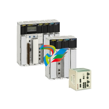
 Modicon X80 modules
 -
 Schneider Modicon M241 Micro PLC
 -
 Altivar 320 Variable Frequency Drive VFD
 -
 Lexium 28 Servo Drives and Motors
 -
 Modicon TM3 Expansion I/O modules for M221. M241. M251
 -
 Schneider Modicon M221 Nano PLC
 -
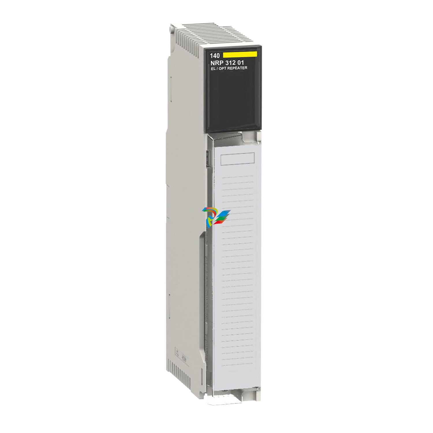 140NRP31201 Ethernet fibre converter SM/LC 2CH - 100 MB
 -
 Schneider Ethernet fibre converter MM/LC 2CH - 100 MB 140NRP31200
 -
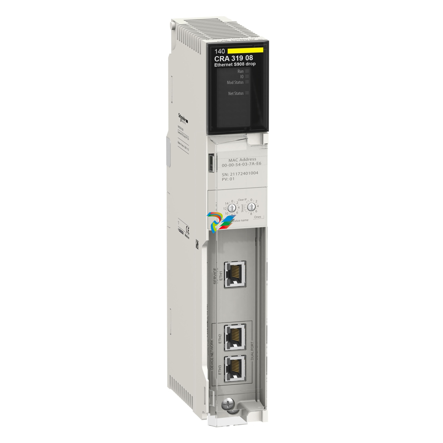 Schneider M580 Quantum S908 RIO Drop Adapter 140CRA31908
 -
 Schneider Quantum RIO Drop E/IP 1CH 140CRA31200
 -
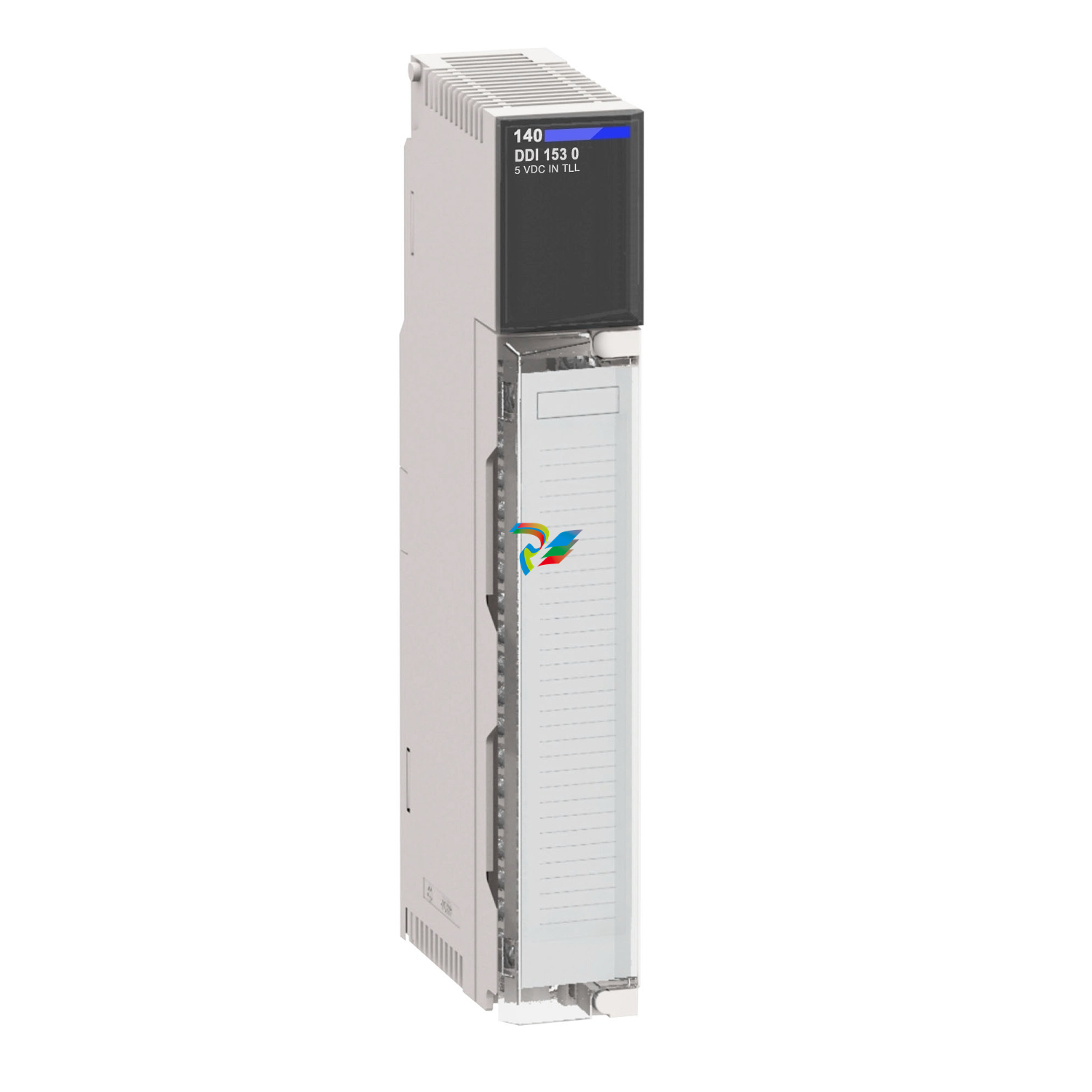 discrete input module Modicon Quantum - 16 I - 10..60 V DC 140DDI84100
 -
 Schneider 140ACI03000 analog input module Modicon Quantum - 8 I multirange
 -
 Schneider Modicon Quantum PAC
 -
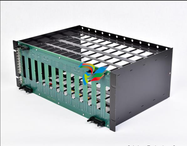 ABB IEMMU21 Module Mounting Unit
 -
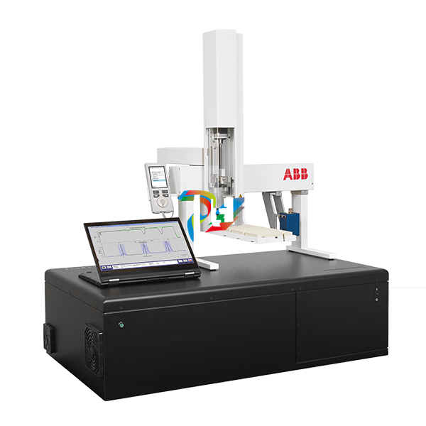
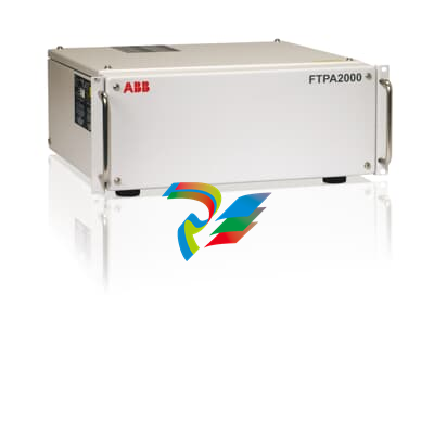 FT-NIR process analyzer for pharmaceutical and life sciences industries FTPA2000-260PH
 -
ABBFT-NIR process analyzer - multi-point fiber optic measurement FTPA2000-260
-
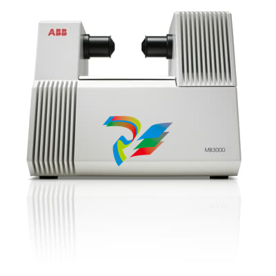 ABB FT-NIR analyzer for pharmaceutical industry MB3600-PH
 -
 ABB Heavy oils analyzer MB3600-HP12
 -
 ABB Hydrocarbons analyzer MB3600-HP10
 -
 PET Packaging Analyzer MB3600-CH80 ABB
 -
ABB Polyol analyzer MB3600-CH70
-
 ABB Biodiesel analyzer MB3600-CH30
 -
 ABB FT-IR analyzer for pharmaceutical industry MB3000-PH
 -
 Natural Gas Chromatograph Analzyer Packages
 -
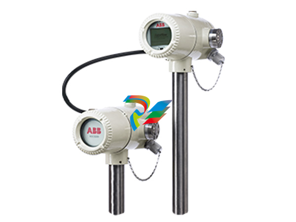 Natural Gas Chromatograph NGC8209
 -
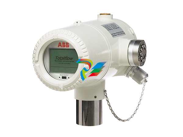 Natural Gas Chromatograph NGC8207 ABB
 -
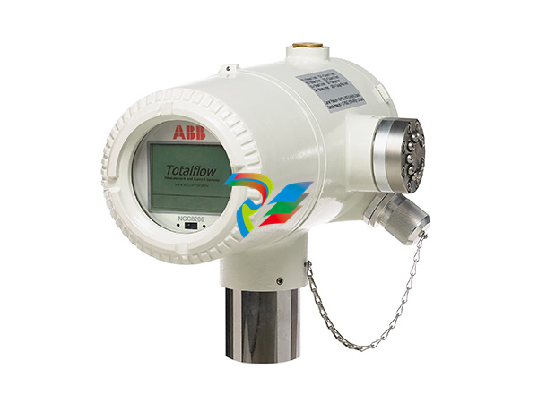 ABB Natural Gas Chromatographs NGC8206
 -
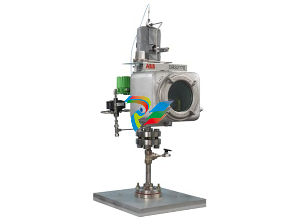 ABB Dynamic Reflux Sampler DRS2170
 -
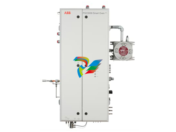 Process Gas Chromatographs PGC5009 Fast PGC
 -
 Process Gas Chromatographs PGC5007 Total sulfur analyzer
 -
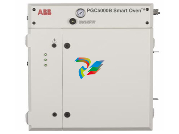 ABB Process Gas Chromatographs PGC5000C Smart oven
 -
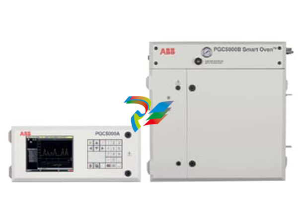
ABB Process Gas Chromatographs PGC5000B Smart Oven
-
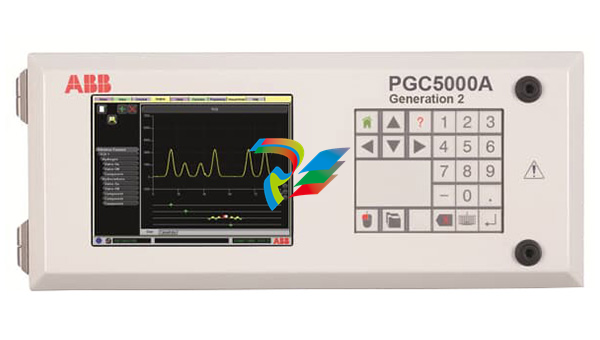 ABB Process Gas Chromatographs PGC5000A Generation 2 Master Controller
 -
 Process Gas Chromatograph PGC1000
 -
 Reid vapor pressure analyzers RVP4500 Series abb
 -
 Color analyzer Aztec AW637 ABB
 -
 UviTec BOD/COD Field Meter
 -
 ABB Ammonia analyzer Aztec AW632
 -
 ABB Ammonia analyzer Aztec AAM631
 -
 ABB Aluminium analyzer Aztec AW631
 -
 Enhanced performance QC rackmount gas analyzers GLA351 series ABB
 -
 ABBEnhanced performance benchtop gas analyzers GLA431 series
 -
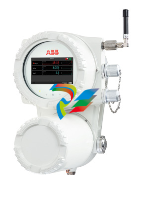 ABB Sensi+™: Natural gas analyzer
 -
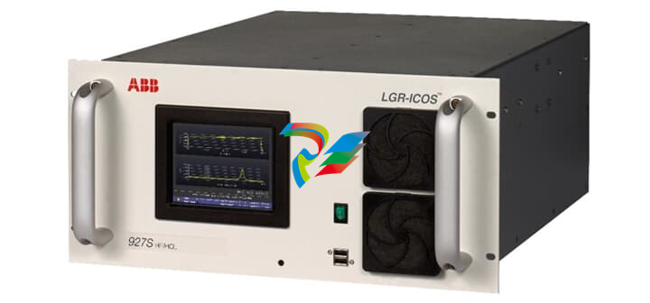 Rackmount gas analyzers GLA231 series ABB
 -
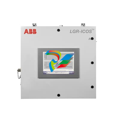 ABB OA-ICOS Industrial wallmount analyzers GLA531 Series
 -
 ABB CLD NOx analyzer CL3020
 -
 Sample Gas Feed Unit SCC-F ABB
 -
 Sample Gas Cooler SCC-C ABB
 -
 CEMcaptain GAA610-M
 -
 Hot/wet extractive system ACF5000
 -
 Advance Optima AO2000 Integrated analyzer system solution
 -
 In-Situ-Cross-Stack-Laser-Analyzer ABB
 -
 ABB H2 purity and purge gas monitor AK100
 -
 High temperature combustion gas oxygen analyzer Endura AZ25
 -
 ABB Combustion gas oxygen analyzer Endura AZ20
 -
 Combustion gas oxygen analyzer Endura AZ30 ABB
 -
 Oxygen and carbon monoxide equivalent (COe) analyzer Endura AZ40 ABB
 -
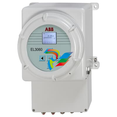 ABB EasyLine EL3060
 -
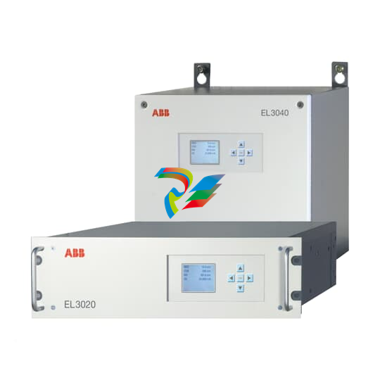 ABB EasyLine EL3000 Continuous gas analyzer
 -
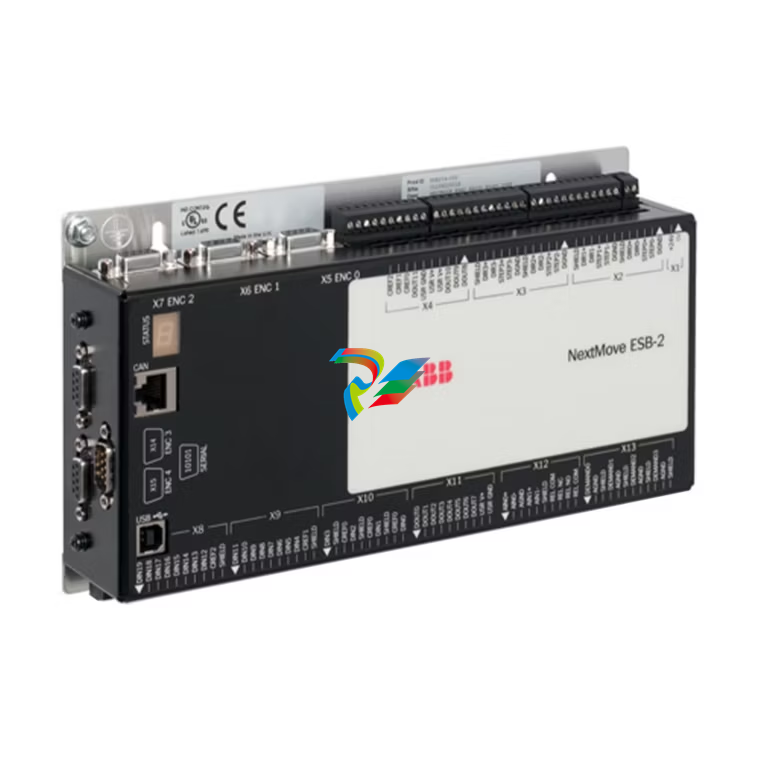 NextMove ESB-2 motion controllers
 -
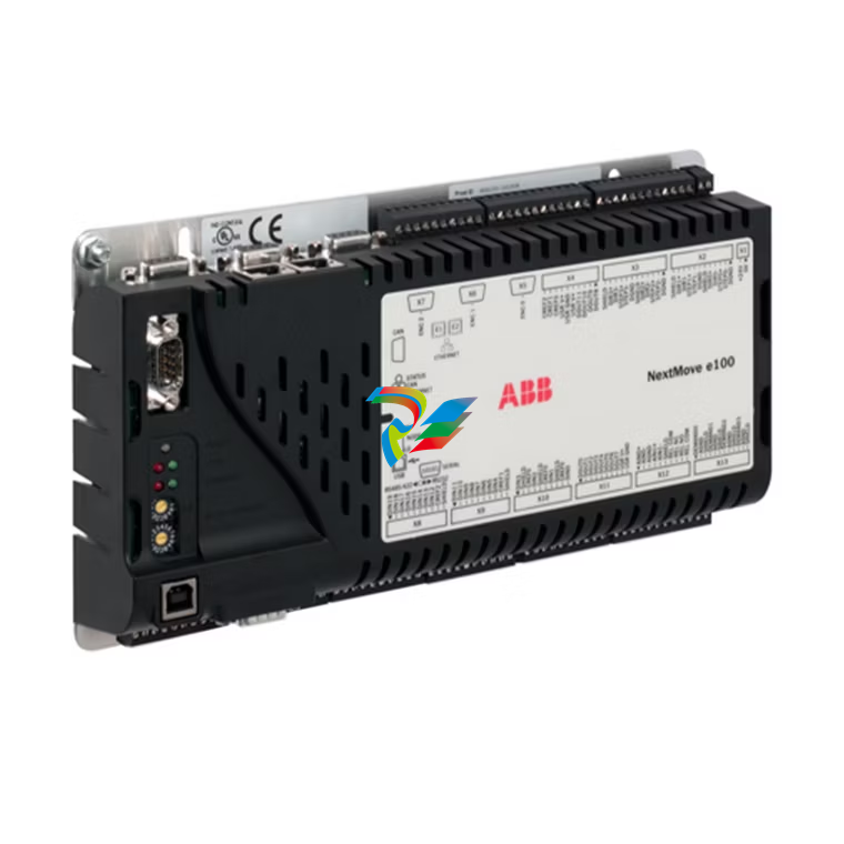 NextMove e100 motion controllers ABB
 -
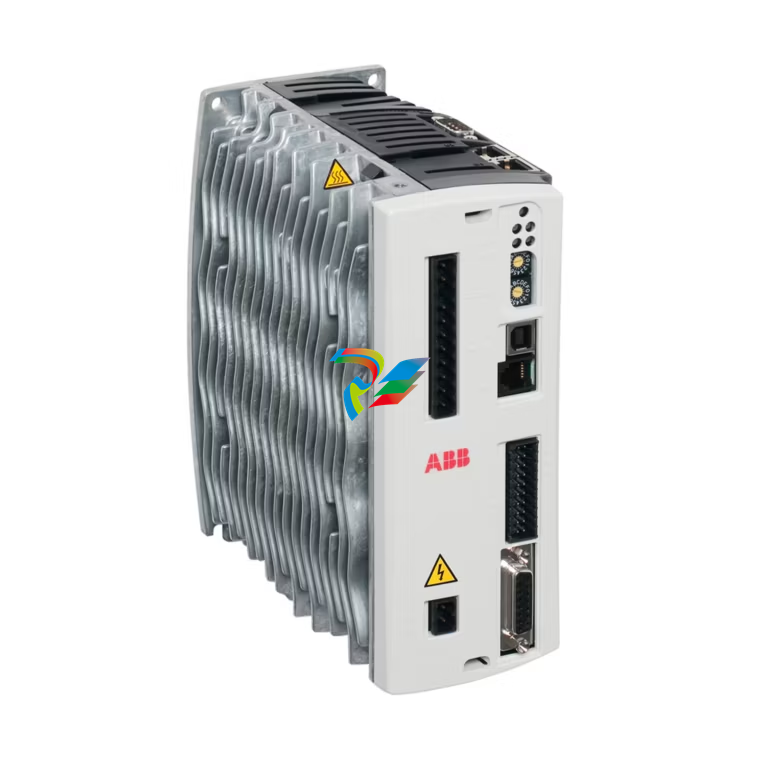
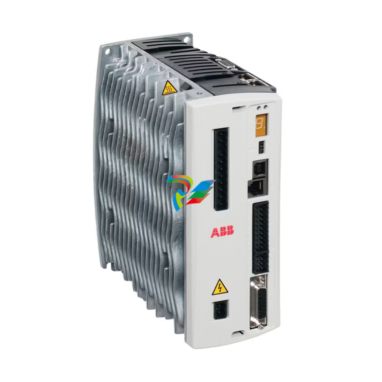 MicroFlex e150 servo drives
 -
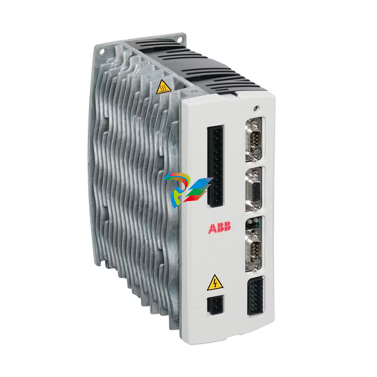
 MicroFlex e100 servo drives
 -
 MicroFlex analog servo drives
 -
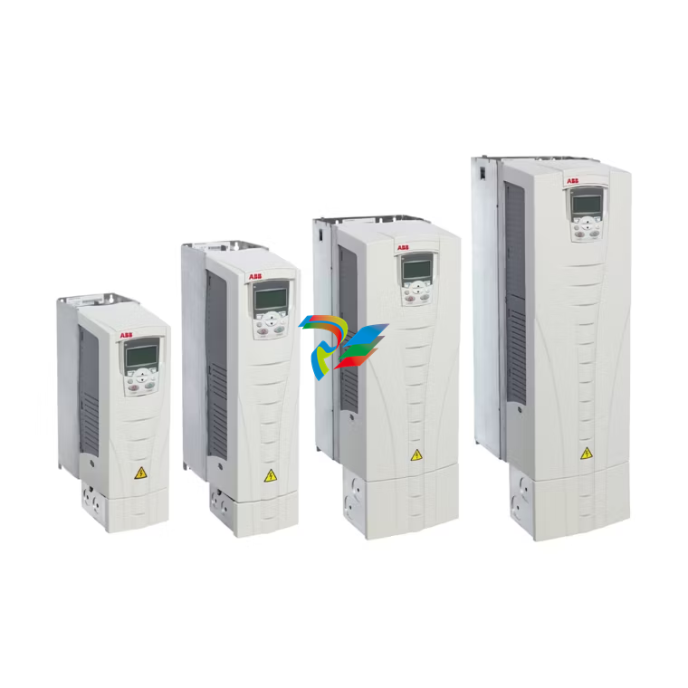 ACS550 drives ABB
 -
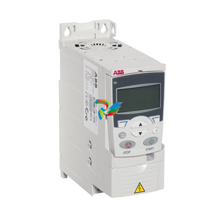 ACS355 drives ABB
 -
 ACS320 drives ABB
 -
 ABB ACS310 drives
 -
 ACS150 drives ABB
 -
 ACS55 drives ABB
 -
 Bently Nevada 2300/25 Vibration Monitors
 -
Bently Nevada 2300/20-RU 2300/20-CN Monitoring controller
-
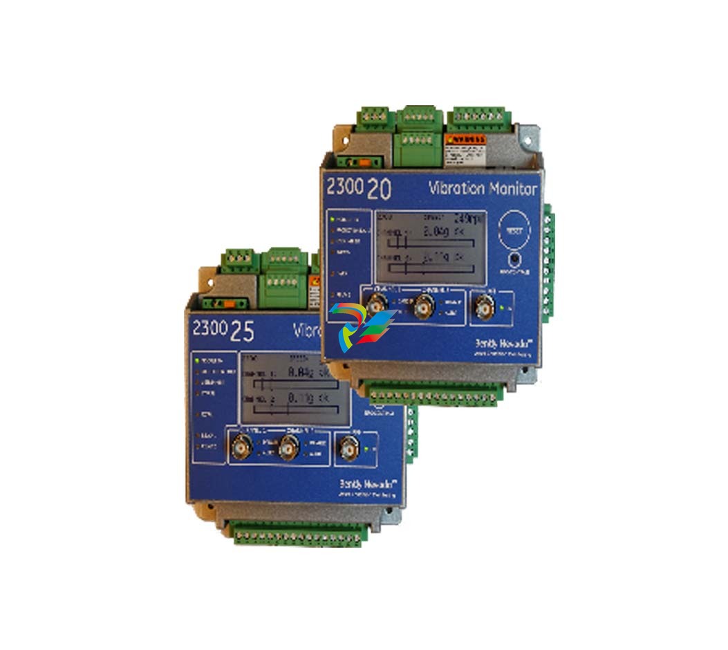 Bently Nevada M 2300/20 and 2300/25 2300 Vibration Monitors
 -
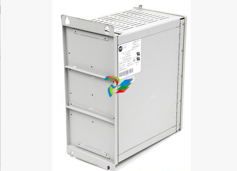 A-B IMC™ S Class Compact Motion Controllers
 -
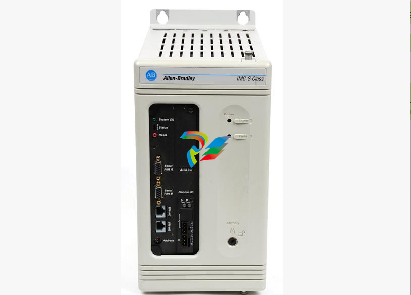 A-B 4100-234-R IMC™ S Class Compact Motion Controllers
 -
 B&R Power Panel 300/400
 -
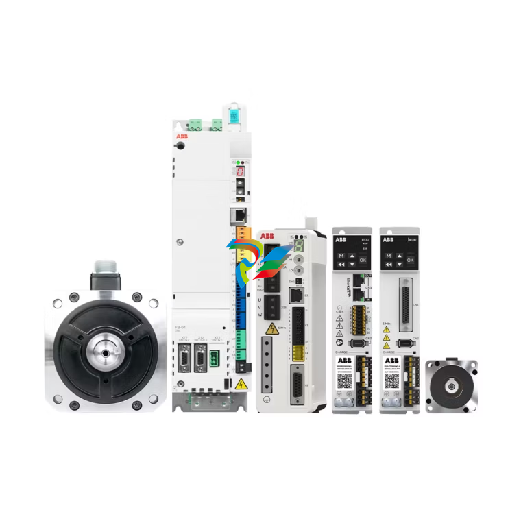 ABB Servo products
 -
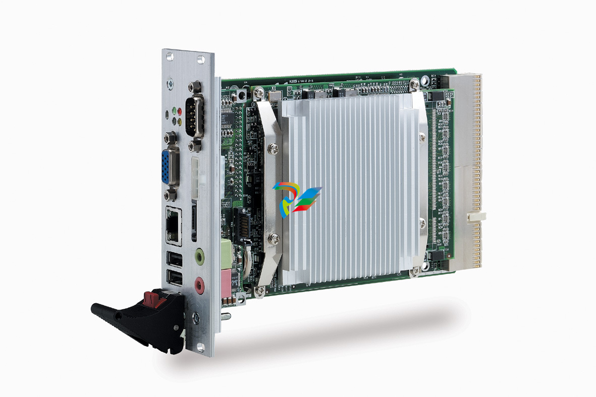 ADLINK cPCI-3840 Processor module
 -
 ACQ580 drives ABB
 -
 ACQ80 drives abb
 -
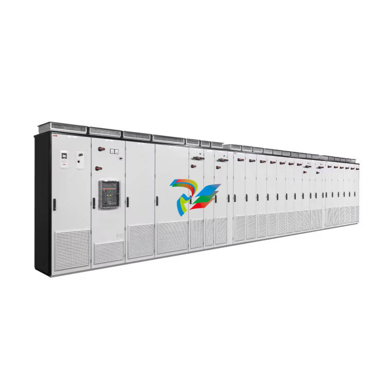
 ACH580 drives ABB
 -
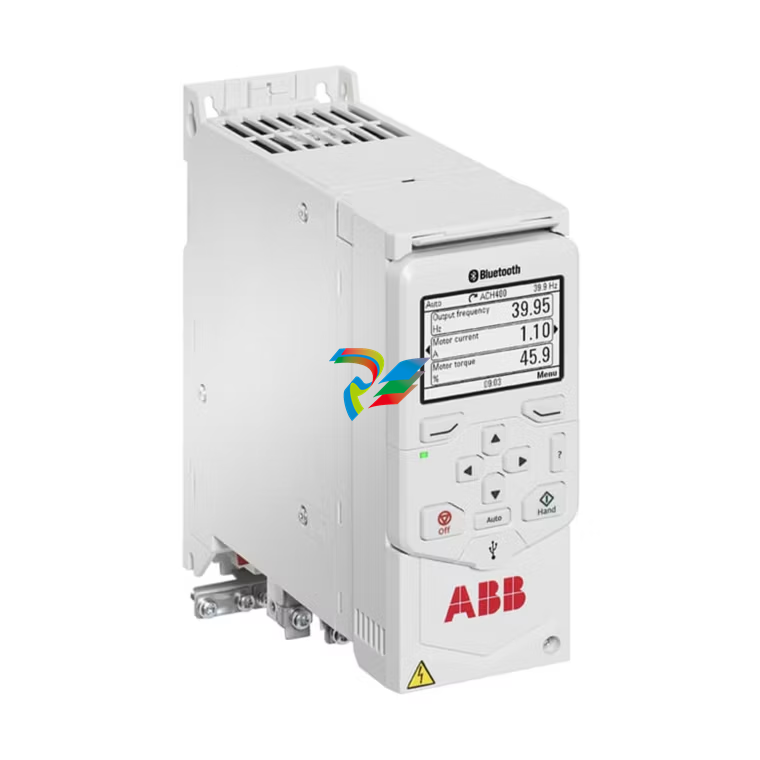 ACH480 drives ABB
 -
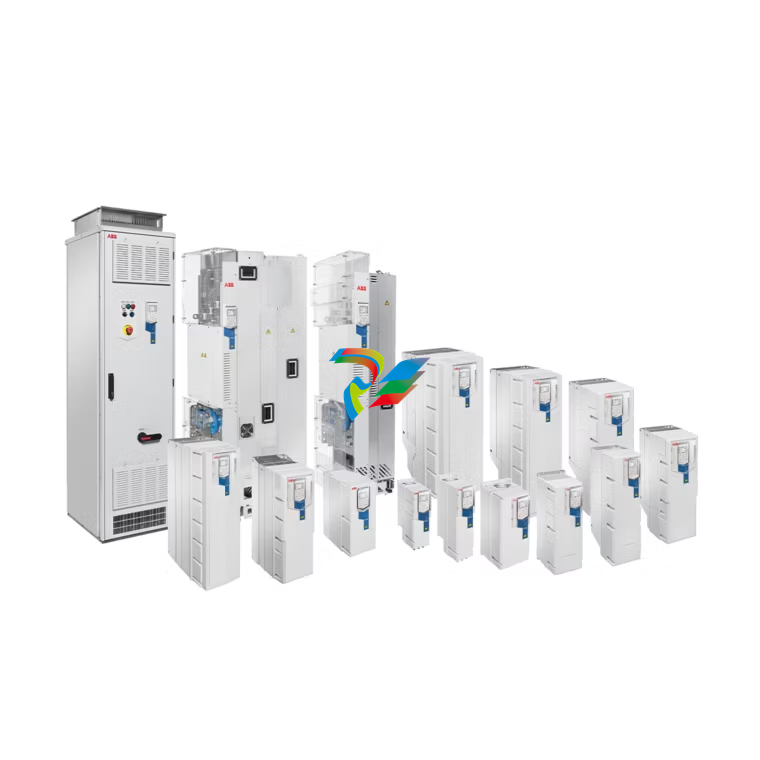
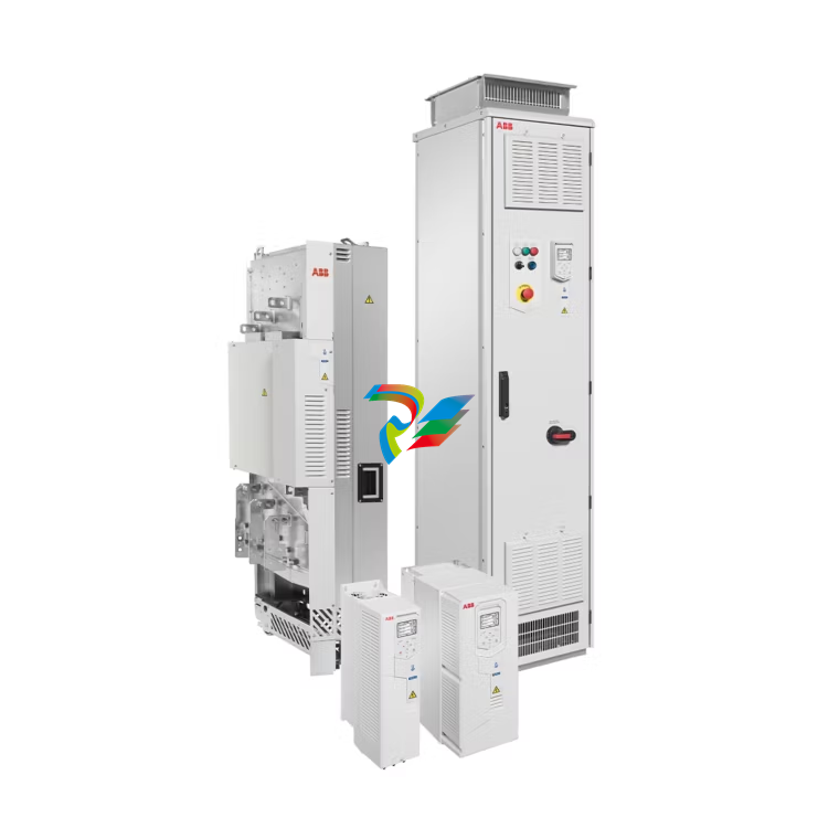
 ACS880 multidrives ABB
 -
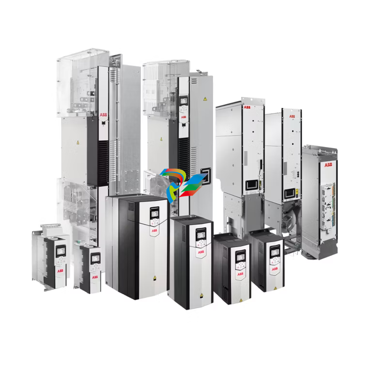 ABB ACS880 drive modules
 -
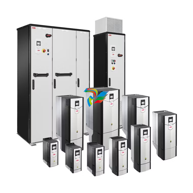 ACS880 single drives abb
 -
 ACS880-M04 drives ABB
 -
 ACS380-E drives ABB
 -
 ABB ACS380 drives
 -
ACS280 drives ABB
-
.png) ABB ACS255 drives (for US market only)
ABB ACS255 drives (for US market only) -
 ACS180 drives ABB
 -
 S500-XC I/O modules ABB
 -
 S500-S I/O modules ABB
 -
 S500-eCo I/O modules ABB
 -
 AC500-XC Communication interface modules ABB
 -
 S500-S I/O modules Terminal units
 -
 AC500-S S500 I/O modules ABB
 -
 AC500-S CPUs ABB
 -
 ABB AC500-S
 -
 Automation Builder ABB
 -
 AC500-eCo Accessories ABB
 -
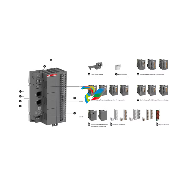
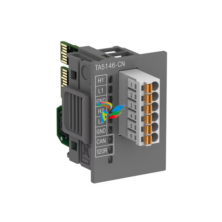 ABB AC500-eCo option modules
 -
 AC500 Condition monitoring system CMS ABB
 -
 ABB S500 I/O modules Terminal units
 -
 S500 I/O modules ABB
 -
 ABB AC500 Communication interface modules
 -
 ABB AC500 communication modules
 -
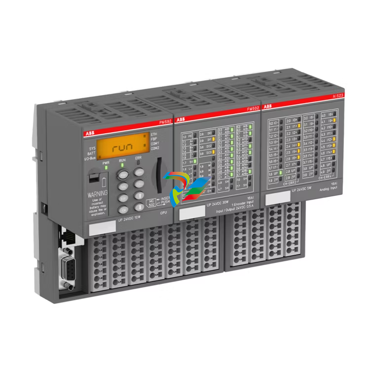
 ABB AC500 PLCs
 -
 ABB AC500-eCo
 -
 ABB AC500-eCo CPU
 -
 ABB AC500-eCo CPUs
 -
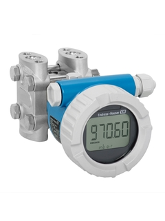 Differential pressure Deltabar PMD55
 -
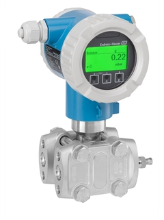 Deltabar PMD75B - differential pressure transmitter
 -
 Endress+Hauser Deltabar PMD55B - differential pressure transmitter
 -
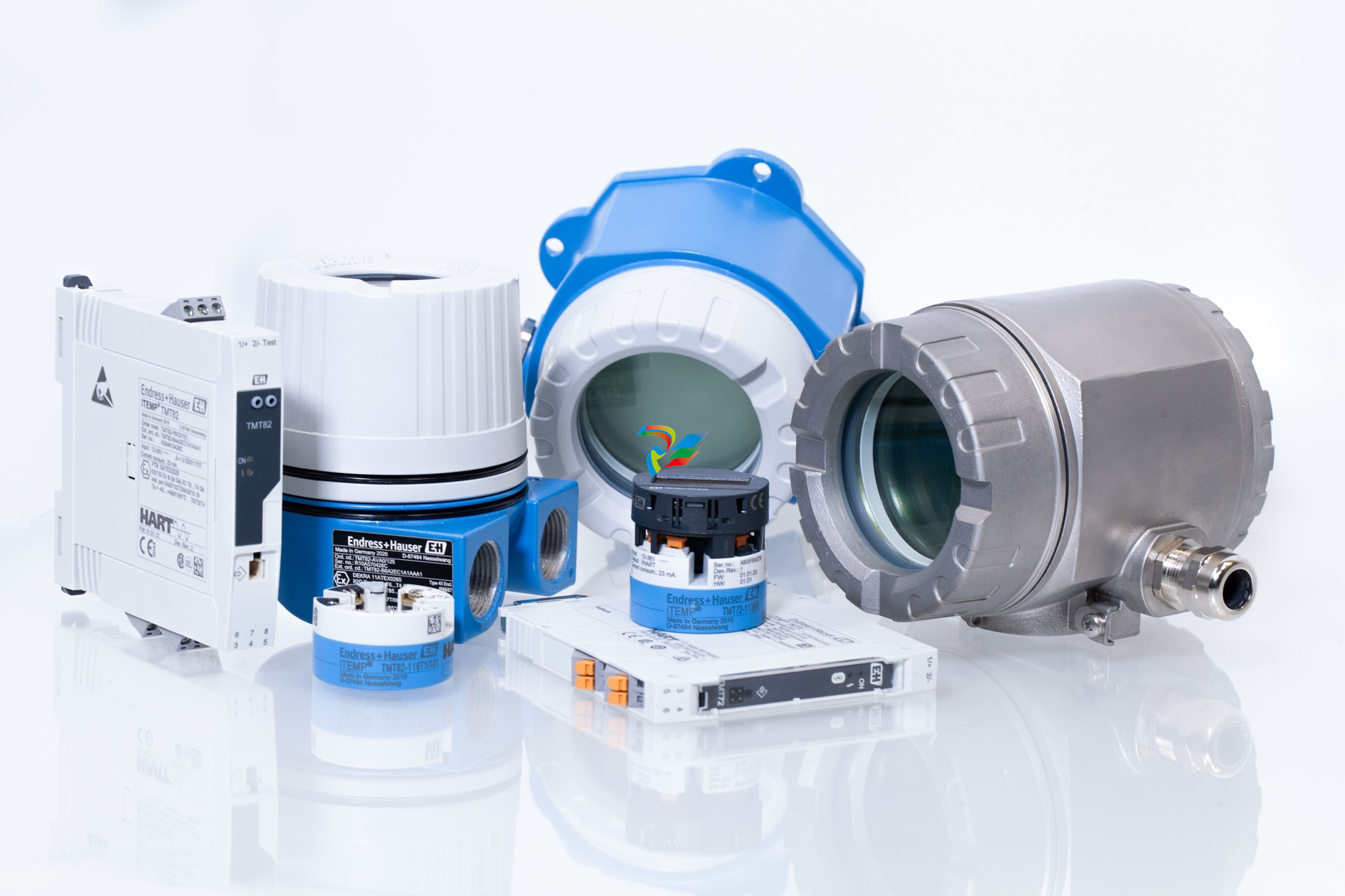 Regarding the temperature transmitter HART
 -
 Regarding the Endress+Hauser temperature transmitter
 -
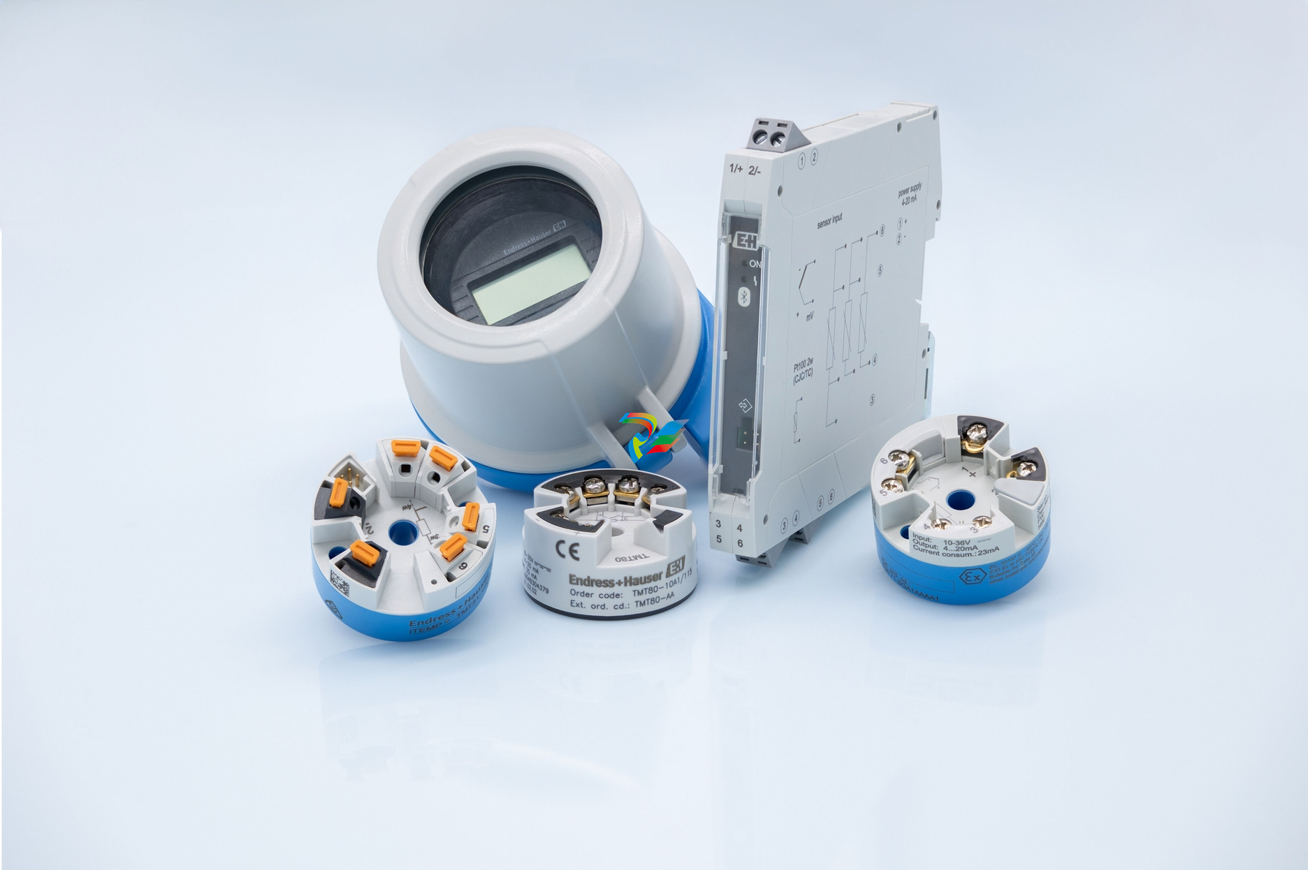
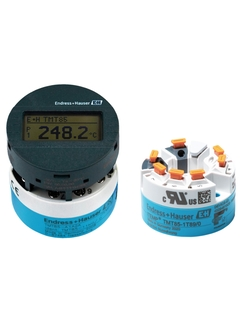
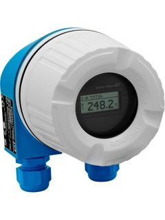
 iTEMP TMT80 temperature transmitter
 -
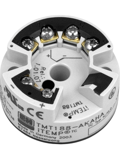 iTEMP TMT188 temperature transmitter Endress+Hauser
 -
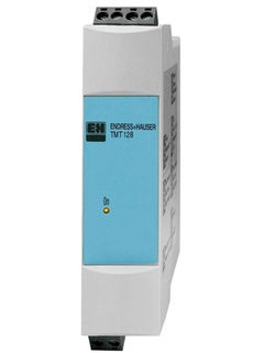 Endress+Hauser iTEMP TMT128 temperature transmitter
 -
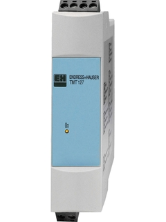 Endress+Hauser iTEMP TMT127 temperature transmitter
 -
 iTEMP TMT85 temperature transmitter
 -
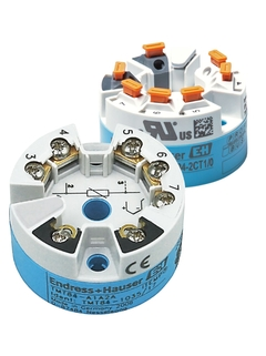 Endress+Hauser iTEMP TMT84 temperature transmitter
 -
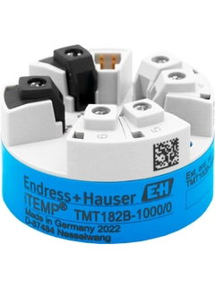 iTEMP TMT182B temperature transmitter Endress+Hauser
 -
 iTEMP TMT86 temperature transmitter
 -
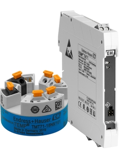 iTEMP TMT71 temperature transmitter Endress+Hauser
 -
 Endress+Hauser iTEMP TMT36 temperature transmitter
 -
 Endress+Hauser iTEMP TMT31 temperature transmitter
 -
 iTEMP TMT142B temperature transmitter

