DCS; Industrial control system
NameDescriptionContent
NEW CENTER
Current Location:

ABB DCS800 Drives

From:ABB | Author:LIAO | Time :2025-07-28 | 6 Browse: | Share:

Safety instructions

What this chapter contains

 This chapter contains the safety instructions which you must follow when installing,

 operating and servicing the drive. If ignored, physical injury or death may follow, or

 damage may occur to the drive, the motor or driven equipment. Read the safety instructions 

before you work on the unit.


To which products this chapter applies

The information is valid for the whole range of the product DCS800, the converter modules DCS800-S0x size D1 to D7, field exciter units DCF80x, etc. like the Rebuild Kit DCS800-R00-9xxx.


Use of warnings and notes

There are two types of safety instructions throughout this manual: warnings and notes. Warnings caution you about conditions which can result in serious injury or death and/or damage to the equipment. They also tell you how to avoid the danger. Notes draw attention to a particular condition or fact, or give information on a subject. The warning symbols are used as follows:

Dangerous voltage warning warns of high voltage which can cause physical injury and/or damage to the equipment. General danger warning warns about conditions, other than those caused by electricity, which can result in physical injury or death and/or damage to the equipment. Electrostatic sensitive discharge warning warns of electrostatic discharge which can damage the equipment.

Installation and maintenance work

These warnings are intended for all who work on the drive, motor cable or motor. Ignoring the instructions can cause physical injury or death and/or damage to the equipment..

• Only qualified electricians are allowed to install and maintain the drive!

• Never work on the drive, motor cable or motor when main power is applied. Always ensure by measuring with a multimeter (impedance at least 1 Mohm) that: 1. Voltage between drive input phases U1, V1 and W1 and the frame is close to 0 V. 2. Voltage between terminals C+ and D- and the frame is close to 0 V. 

• Do not work on the control cables when power is applied to the drive or to the external control circuits. Externally supplied control circuits may cause dangerous voltages inside the drive even when the main power on the drive is switched off. • Do not make any insulation resistance or voltage withstand tests on the drive or drive modules. 

• Isolate the motor cables from the drive when testing the insulation resistance or voltage withstand of the cables or the motor. 

• When reconnecting the motor cable, always check that the C+ and D- cables are connected with the proper terminal. Note: 

• The motor cable terminals on the drive are at a dangerously high voltage when the main power is on, regardless of whether the motor is running or not. 

• Depending on the external wiring, dangerous voltages (115 V, 220 V or 230 V) may be present on the relay outputs of the drive system (e.g. SDCS-IOB-2 and RDIO). 

• DCS800 with enclosure extension: Before working on the drive, isolate the whole drive from the supply

 These instructions are intended for all who are responsible for the grounding of the drive. Incorrect grounding can cause physical injury, death and/or equipment malfunction and increase electromagnetic interference.

WARNING!

• Ground the drive, motor and adjoining equipment to ensure personnel safety in all circumstances, and to reduce electromagnetic emission and pick-up. 

• Make sure that grounding conductors are adequately sized and marked as required by safety regulations. • In a multiple-drive installation, connect each drive separately to protective earth (PE ). 

• Minimize EMC emission and make a 360° high frequency grounding (e.g. conductive sleeves) of screened cable entries at the cabinet lead-through plate. 

• Do not install a drive equipped with an EMC filter to an ungrounded power system or a high resistance-grounded (over 30 ohms) power system. Note: 

• Power cable shields are suitable as equipment grounding conductors only when adequately sized to meet safety regulations. 

• As the normal leakage current of the drive is higher than 3.5 mA AC or 10 mA DC (stated by EN 50178, 5.2.11.1), a fixed protective earth connection is required.

Printed circuit boards and fiber optic cables

These instructions are intended for all who handle the circuit boards and fiber optic cables. Ignoring the following instructions can cause damage to the equipment.

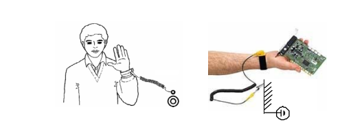
WARNING! The printed circuit boards contain components sensitive to electrostatic discharge. Wear a grounding wrist band when handling the boards. Do not touch the boards unnecessarily

Use grounding strip:
WARNING! Handle the fiber optic cables with care. When unplugging optic cables, always grab the connector, not the

 cable itself. Do not touch the ends of the fibers with bare hands as the fiber is extremely sensitive to dirt. The minimum 

allowed bend radius is 35 mm (1.4 in.).

Mechanical installation

These notes are intended for all who install the drive. Handle the unit carefully to avoid damage and injury.

WARNING!

• DCS800 sizes D4 ... D7: The drive is heavy. Do not lift it alone. Do not lift the unit by the front cover. Place units D4, D4+ and D5 only on their back. DCS800 sizes D5 ... D7: The drive is heavy. Lift the drive by the lifting lugs only. Do not tilt the unit. The unit will overturn from a tilt of about 6 degrees. 
• Make sure that dust from drilling does not enter the drive when installing. Electrically conductive dust inside the unit may cause damage or lead to malfunction. 

• Ensure sufficient cooling. 

• Do not fasten the drive by riveting or welding.

These warnings are intended for all who plan the operation of the drive or operate the drive. Ignoring the instructions can cause physical injury or death and/or damage to the equipment.

• Before adjusting the drive and putting it into service, make sure that the motor and all driven equipment are suitable for operation throughout the speed range provided by the drive. The drive can be adjusted to operate the motor at speeds above and below the base speed. 

• Do not control the motor with the disconnecting device (disconnecting mains); instead, use the control panel keys and , or commands via the I/O board of the drive. 

• Mains connection You can use a disconnect switch (with fuses) to disconnect the electrical components of the drive from the mains for installation and maintenance work. The type of disconnect switch used must be as per EN 60947-3, Class B, so as to comply with EU regulations, or a circuit-breaker type which switches off the load circuit by means of an auxiliary contact causing the breaker's main contacts to open. The mains disconnect must be locked in its "OPEN" position during any installation and maintenance work.

• EMERGENCY STOP buttons must be installed at each control desk and at all other control panels requiring an emergency stop function. Pressing the STOP button on the control panel of the drive will neither cause an emergency stop of the motor, nor will the drive be disconnected from any dangerous potential. To avoid unintentional operating states, or to shut the unit down in case of any imminent danger according to the standards in the safety instructions it is not sufficient to merely shut down the drive via signals "RUN", "drive OFF" or "Emergency Stop" respectively "control panel" or "PC tool". 

• Intended use The operating instructions cannot take into consideration every possible case of configuration, operation or maintenance. Thus, they mainly give such advice only, which is required by qualified personnel for normal operation of the machines and devices in industrial installations. If in special cases the electrical machines and devices are in-tended for use in non-industrial installations - which may require stricter safety regulations (e.g. protection against contact by children or similar) - these additional safety measures for the installation must be provided by the customer during assembly. Note: 

• When the control location is not set to Local (L not shown in the status row of the display), the stop key on the control panel will not stop the drive. To stop the drive using the control panel, press the LOC/REM key and then the stop key .


Chapter overview

This chapter describes briefly the operating principle and construction of the converter modules in short.

The DCS800

The DCS800-S size D1 - D7 are intended for controlling DC motors.

Mechanical installation

Chapter overview This chapter describes the mechanical installation of the DCS800.

Unpacking the unit 

• Open the box, 

• take out shock dampers, 

• separate manual and accessories.Attention: Do not lift the drive by the cover!

Delivery check

Check that there are no signs of damage. Before attempting installation and operation, check the information on the nameplate of the converter module to verify that the unit is of the correct type. The label includes an IEC rating, cULus, C-tick (N713) and CE markings, a type code and a serial number, which allow individual identification of each unit. The remaining digits complete the serial number so that there are no two units with the same serial number. See an example nameplate below

Before installation

Install the drive in an upright position with the cooling section facing a wall. Check the installation site according to the requirements below. Refer to chapter Dimensions and weights for frame details. Requirements for the installation site See chapter Technical data for the allowed operation conditions of the drive. Wall The wall should be as close to vertical as possible, of non-flammable material and strong enough to carry the weight of the unit. Check that there is nothing on the wall to inhibit the installation. Floor The floor or material below the installation should be non-flammable. Free space around the unit Around the unit free space is required to enable cooling airflow, service and maintenance see chapter Dimensions and weights.

Cabinet installation.

The required distance between parallel units is five millimetres (0.2 in.) in installations without the front cover. The cooling air entering the unit must not exceed +40 °C (+104 °F).

Preventing cooling air recirculation Unit above another

Terminal cover according to VBG 4 regulations For converter modules size D1 - D4 shrouds for protection against contact are provided.

Connecting the external control unit of a D7 module (+P906)

During installation the SDCS-CON-4 needs to be connected with the SDCS-PIN-51 using two shielded 16 pole flat cables. These cables connect terminals X12 with each other, as well as terminals X13. For easier access to the terminals in the control unit, connecting boards SDCS-CCB-4 or SDCS-CCB-5 are placed close to the lower end of the metal frame. When connecting X12 and X13 make sure the flat cables are marked at both ends, one with X12, the other with X13. Worst case put stickers on! Wedge the blank screen of the flat cable in position using the screen clamp, then place the plug into its socket.

Fuses F3.2 and F3.3 are used as line protectors and cannot protect the field supply unit. Only pure HRC fuses or miniature circuit-breakers must be used. Semiconductor fuses will be tripped, for example, by the transformer’s inrush current.

Semiconductor fuses (F1) and fuse holders for armature circuit The converters are subdivided into two groups: 

• Unit sizes D1, D2, D3 and D4 with rated currents up to 1000 A require external fuses. 

• In unit sizes D4+, D5, D6 and D7 with rated currents from 900 A to 5200 A, branch fuses are internally installed (no additional external AC or DC fuses are needed). The fourth column of the table below assigns the AC fuse to the unit. In case the converter should be equipped with DC fuses, use the same type of fuse as on the AC side


EMC filters (E1) Filter in a grounded line (earthed TN or TT network) The filters are suitable for grounded lines only, for example in public European 400 VAC lines. According to EN 61800-3 filters are not needed in insulated industrial networks with own supply transformers. Furthermore they could cause safety risks in such floating lines (IT networks). According to EN 61800-3 filters are not needed in industrial zone (Second Environment) for DCS800 drives above 100 ADC rated current. For rated currents below 100 ADC the filter requirement is identical to Light Industry (First Environment). Three-phase filters EMC filters are necessary to fulfil the standard for emitted interference if a converter shall be run at a public low voltage line, in Europe for example with 400 VAC. Such lines have a grounded neutral conductor. ABB offers suitable three-phase filters for 400 VAC. For 440 VAC public low voltage lines outside Europe 500 VAC filters are available. Optimize the filters for the real motor currents: IFilter = 0.8 • IMOT max; the factor 0.8 respects the current ripple. Lines with 500 VAC up to 1000 VAC are not public. There are local networks inside factories, and they do not supply sensitive electronics. Therefore converters do not need EMC filters if they shall run with 500 VAC and more.


Converters size D4+ - D7 configuration using external field exciters DCF803, DCF804 Wiring the drive according to this diagram offers the highest degree of monitoring functions done by the drive. Field converters DCF803 / DCF804 are equipped with their own synchronization and must be supplied from independent mains supply voltage max. 500 V (single-phase or 3-phase).


Start, Stop and E-Stop control The relay logic is splitted into four parts: 1: Generation of the On / Off and Start / Stop command: The commands represented by K20 and K21 (latching interface relay) can also be generated by a PLC and transferred to the terminals of the converter either by relays, using galvanic isolation or directly via 24 V signals. There is no need to use hardwired signals. Transfer these commands via serial communication. Even a mixed solution can be realized by selecting different possibilities for the one or the other signal (see parameter group 11). 2: Generation of control and monitoring signals: Control the main contactor K1 for the armature circuit by the dry contact of DO8 located on the SDCS-PIN-4 or SDCS-POW-4. The status of motor (K6) and converter (K8) fans can be monitored by means of MotFanAck (10.06) and ConvFanAck (10.20). 3: Off2 (Coast Stop) and Off3 (E-stop): Beside On / Off and Start / Stop the drive is equipped with two additional stop functions Off2 (Coast Stop) and Off3 (E-stop) according to Profibus standard. Off3 (E-stop) is scalable via E StopMode (21.04) to perform stop category 1. Connect this function to the E-stop push button without any time delay. In case of E StopMode (21.04) = RampStop the K15 timer relay must be set longer than E StopRamp (22.04). For E StopMode (21.04) = Coast the drive opens the main contactor immediately. Off2 (Coast Stop) switches the DC current off as fast as possible and prepares the drive to open the main contactor or drop the mains supply. For a normal DC motor load the time to force the DC current to zero is below 20 ms. This function should be connected to all signals and safety functions opening the main contactor. This function is important for 4-Q drives. Do not open main contactor during regenerative current. The correct sequence is: 1. switch off regenerative current 2. then open the main contactor In case the E-stop push button is hit, the information is transferred to the converter via DI5. In case E StopMode (21.04) = RampStop or TorqueLimit the converter will decelerate the motor and then open the main contactor. If the drive has not finished the function within the K15 timer setting, the drive must get the command to switch off the current via K16. After the K16 timer has elapsed, the main contactor is opened immediately, independent of the drive's status.


  • Honeywell 30735863-502 - SWITCH
  • Honeywell TK-CCR014 - REDUNDANT NET INTERFACE NEW ORIGINAL FREE EXPEDITED SHIPPING/
  • Honeywell 51403165-400 - new 51403165400/
  • Honeywell318-049-001 quot100 Batteries(Japan Liion2Ah14.8Wh)INTERMEC/ PR2,PR3 P/N
  • Honeywell FC-PSU-UNI2450U - Power Supply
  • Honeywell 965-0676-010 - WARNING COMPUTER SV
  • Honeywell 51403519-160 - Module
  • Honeywell 107843 - HOUSING CARBON FILE P/N NE COND # 11438 (4)
  • Honeywell VR434VA5009-1000 - Brand new in box Condensing boiler valve DHL fast shipping
  • Honeywell SPXCDALMFX - plc new FREE EXPEDITED SHIPPING/
  • Honeywell BCM-PWS - BCM-ETH BCM-MS/TP BCM-MS/TP Network controller setFedEx or DHL
  • Honeywell YSTR12D-22/C/-2J0DFA/BE/400/T/-CM.HO.TG.SB.SM,ZS,F1,LP,/FX/,1C-BT - UNMP
  • Honeywell IWS-1603-HW - 90-250VAC 1.0A UNMP
  • Honeywell 51304386-150 - MEASUREX Factory Packed
  • Honeywell CC-IP0101 - Profibus Gateway Module
  • Honeywell CC-PFB401 - / CCPFB401 (NEW IN BOX)
  • Honeywell 50071726 - St 800 Series Pressure Transmitter Remote Diaphragm 11-42VDC
  • Honeywell 621-2150 - / 6212150 (NEW NO BOX)
  • Honeywell 80360206-001 - USED YAMATAKE CLI BOARD
  • Honeywell BMDX001A-001 - ACCURAY / BOARD BMDX001A001
  • Honeywell XCL8010A - New CPU Controller.
  • Honeywell PGM-7320 - 1PCS NEW Rae Systems MiniRAE 3000 Portable VOC Monitor#XR
  • Honeywell BK-G40 - U65 *FULL INSTALLATION* Gas Meter 3?± Inlet/Outlet Spool NEW UNUSED
  • Honeywell DM106-0-B-00-0-R-1-00000-000-E0 - DPR100 250V NSNP
  • Honeywell KFD840 - PRIMARY FLIGHT DISPLAY CORE PN: 066-01206-0104
  • Honeywell 51401914-100 - 51400996-100
  • Honeywell TK-PRS021 - Module Via FEDEX/DHL
  • Honeywell C7012A1145 - 1PC New UV Flame Detector Expedited Shipping
  • Honeywell OV210 - Baxter Bakery Oven Igition Control. For DRO. 00-616973 NEW
  • Honeywell 51304431-125 - 1PC New /51304431125 1 year warranty#XR
  • Honeywell QPP-0002 - Quad Processor Module / 5 Vdc / Massima 1.2A/24Vdc/max.25mA
  • Honeywell QPP-0002 - Quad Processor Module / 5Vdc / Max. 1.2A/24Vdc/max.25mA
  • Honeywell 8C-PCNT02 - 514543363-275 module
  • Honeywell DPCB21010002 - Tata Printed Circuit Board
  • Honeywell DPCB21010002 - Tata Printed Circuit Board Rev: 0
  • Honeywell 001649-M5T028 - Tata Printed Circuit Board Rev: 0
  • Honeywell YSTD924-(J2A)-00000-FF,W3,TP,TG,SS - NSFS
  • Honeywell XF523-A - / XF523A (NEW IN BOX)
  • Honeywell TK-PRS021 - NEW IN STOCK ship by UPS
  • Honeywell 2MLR-AC22 - " 2mlr-dbsf,2mlf-ad4s,2mlf-dc4s,2mlr-ac22 Rack"
  • Honeywell 9436610 - MEASUREX NSMP
  • Honeywell RT10A-L0N-18C12S0E - RT10A.WLAN.IN.6803.CAM.STD.GMS
  • Honeywell 51305896-200 - P:C1 Rev D Nim Modem - FAST SHIP BY Fedex
  • Honeywell TK-FTEB01 - PCL module Brand New Fast Shipping By DHL
  • Honeywell 8694500 - Measurex Control Processor Module
  • Honeywell DR4500 - Truline and DR4300 Circular Chart Recorder
  • Honeywell EC-7850-A-1122 - / EC7850A1122 (NEW IN BOX)
  • Honeywell XNX-UTAI-RNNNN - NEW Universal transmitter DHL Fast delivery
  • Honeywell SPXCDALMFX - plc new One Year Warranty #
  • Honeywell TC-RPFM01 - C200 system card brand new Fast Shipping
  • Honeywell 51196655-100 - NSMP
  • Honeywell XCL8010A - / XCL8010A (USED TESTED CLEANED)
  • Honeywell 51198801-100 - NEW CPU INTERFACE BOARD UPGRADE KIT UPIU 51306154-100
  • Honeywell 84795 - Sputtering Target 5N Al5Cu 7830x11640x13050
  • Honeywell W7704A-1004 - / W7704A1004 (USED TESTED CLEANED)
  • Honeywell RA890G1229 - FOR FSG UV Protectorelay /PL3
  • Honeywell KFS-599B - 071-01576-0101 UHF Communication Control with Mods (28V)
  • Honeywell WPC2000 - WINTRISS 9683001 WINTRISS CLUTCH/BRAKE CONTROL *NO KEYS*
  • Honeywell C7012E1112 - 1PC C7012E 1112 Burner Detector New In Box Expedited Ship #
  • Honeywell 8C-TCNTA1 - C300 system card brand new Fast Shipping
  • Honeywell ANT67A - TCAS Antenna 071-01548-0100 w/ October 2023 Repaired 8130
  • Honeywell CC-PDIS01 - PLC Module Brand New Fast Shipping FedEx or DHL
  • Honeywell R7247C1001 - 2-4SECS NSMP
  • Honeywell ALI-80A - Collins Encoding Altimeter - P/N 622-3975-011 - Tested 8130 -Serviceable
  • Honeywell 001650-M5T028 - Tata Relay Circuit Board
  • Honeywell 51196886-100 - PC BOARDS (126201 - NEW)
  • Honeywell J-HAM10 - NSNP
  • Honeywell TC-IXL062 - 1PCS module New fedex or DHL
  • Honeywell 114M4910-6 - PISTON ASSY PN NS COND 12037
  • Honeywell C7076 - 191002B Sensor Amplifier 220/240v
  • Honeywell 510STR12D21A-B77P - NSNP
  • Honeywell 51304511-200 - Module Nim Modem Via FEDEX/DHL
  • Honeywell IC-600 - Integrated Communication Unit RCZ851E 7510700-806 Removed Working
  • Honeywell TC-IAH161 - 1PC NEW REDUNDANT NET INTERFACE one year warranty#XR
  • Honeywell 2001-100-150-126-280-20-100000 - REMAN
  • Honeywell QPP-0001 - FSC QUAD PROCESSOR PACK QPP MODULE CC V1.4
  • Honeywell 30734558-001 - / 30734558001 (USED TESTED CLEANED)
  • Honeywell STD830-E1HS4AS-1-A-ADB-11C-B-21A0-00-0000 - 4500PSI NSNP
  • Honeywell 900C75-0560 - NEW HC900 Controller module FedEx DHL Fast delivery
  • Honeywell BL870 - Bezel 7014331-921 w/ October 2018 Repaired 8130
  • Honeywell STG77L-E1G000-1-A-CDC-11S-A-20A0-00-0000 - NSMP
  • Honeywell FF-SB14E12K-S2 - / FFSB14E12KS2 (USED TESTED CLEANED)
  • Honeywell 51198685-100 - "Rev. A, 140519-2-LF Power Supply Module 10A 100-240 VAC"
  • Honeywell 942-M96-M - plc new FREE EXPEDITED SHIPPING
  • Honeywell TK-IAH161 - 1PC New ANALOG INPUT TKIAH161 Expedited Shipping
  • Honeywell C7061F2001 - 1PC UV Flame Detector New In Box #
  • Honeywell 0190-20139/D - ONE Sputtering Coating Disc 4N5TI NEW
  • Honeywell 82408667-001 - NEW MEMORY BOARD ROM/RAM 82408667001
  • Honeywell C7012A1194 - NEW IN STOCK ship by UPS
  • Honeywell TK-FTEB01 - NEW IN BOX FTE BRIDGE Brand New Fast Shipping FedEx or DHL
  • Honeywell RA890G1344 - 1pc NEW Combustion Controller DHL or FedEX
  • Honeywell DH-AP-1/ - Miller 3 Workers per System 4-3/4 Ft Overall H Post Anchor
  • Honeywell TCOAV081 - NEW IN BOX ANALOG OUTPUT EXPEDITED SHIPPING
  • Honeywell W7704D1016 - Control Unit
  • Honeywell 9437710 - USED PIDP MEASUREX / 09437710-RP MODULE REV D STOCK 1603
  • Honeywell 51403165-400 - Brand new industrial computer Fast FedEx or DHL
  • Honeywell DC3200-EE-000R-240-00000-E0-0 - New DHL FastShip
  • Honeywell 51305348-100 - / 51305348100 (USED TESTED CLEANED)
  • Honeywell CC-PAIX01 - 1PCS Brand New Expedited Shipping
  • Honeywell 51305890-175 - REV B NEW
  • Honeywell XCL8010A - NEW IN STOCK ship by UPS
  • Honeywell D18-UU0000-D00000-0000-2-0000-00-E - CHART RECORDER CHART RECORDER
  • Honeywell TC-IAH161 - ANALOG INPUT NEW 1PCS
  • Honeywell 10020/1/2 - / 1002012 (NEW IN BOX)
  • Honeywell DC3200-EE-000R-240-00000-E0-0 - Digital Controller UPS Express New Zy
  • Honeywell 2MLR-CPUH/F - 1PC NEW EXPRESS P3097E YL/
  • Honeywell 9437710 - USED PIDP MEASUREX MODULE REV D STOCK 1608
  • Honeywell CC-PAIX02 - Fast Shipping
  • Honeywell DPR500 - Brand New Fast Shipping By DHL
  • Honeywell 10004/I/F - / 10004IF (USED TESTED CLEANED)
  • Honeywell C7012E1112 - 1PCS New in box UV Flame Detector
  • Honeywell HPTZ-361W - Brand New Expedited Shipping
  • Honeywell 10006/2/1 - / 1000621 (NEW NO BOX)
  • Honeywell SC-PCMX01 - 1PC NEW RTU2020 51307195-175 SHIP EXPRESS #P2254E YL
  • Honeywell X-NPMS(H) - 1PC Network Paging Console Fire Equipment Brand New Via DHL
  • Honeywell C7012E1112 - 1Pcs new Explosion-proof flame detector
  • Honeywell 0190-20139/D - 4N5TI Sputtering Coating Disc
  • Honeywell RM7840E1016 - SER. 3 REV. 4141 120VAC 15SEC NSMP
  • Honeywell C7012E1120 - Brand new Fast shipping via DHL
  • Honeywell MU-PSIM11 - 1PCS card Brand New Expedited Shipping
  • Honeywell DPR500 - Brand New Fast Shipping FedEx or DHL
  • Honeywell 2108B2101N - Gas Detector OPTIMA PLUS-UL-HC
  • Honeywell 51403578-100 - Rev F Operator Keyboard 1x Ship By DHL/FEDEX/UPS
  • Honeywell 51403165-400 - ONE industrial computer
  • Honeywell FF-SB12E/R02E-S2/3 - Securitram Pair FF-SB12E02E-S2/3 + FF-SB12R02E-S2/3
  • Honeywell STR12D-21A-1B0AFAAA21BP-1C,DE,MB+XXXX - NSMP
  • Honeywell STR17G-11A-1K0AFCAA21A0-A1,CC,HC,MB,NE,TG,W2,3H+XXXX - NSMP
  • Honeywell TK-FTEB01 - "FTE connection module , 51309512-175 Fast Shipping"