
ABBEasyLine EL3000 Series
Measurement made easy So smart, they’re simple
—
A wide variety of measurement technology
Ů Detectors for multiple process and emission monitoring
applications
Ů Up to five sample components in one gas analyzer
Ů Suitable for measuring flammable gases
Ů Version in Category 3G for measuring non-flammable gases
Ů Performance-tested for emission monitoring according to
EN 15267
Ů QAL3 monitoring according to EN 14181 (optional)
—
Straightforward handling Ů Automatic calibration including control of pump and solenoid valves Ů Simplified calibration with air or integral calibration cells eliminating the need for test gas cylinders Ů Self-monitoring function indicates when maintenance is required
—
Application-oriented design Ů Housing design for 19-inch rack mounting or wall mounting Ů Integrated pneumatics module in model EL3020 (optional) Ů Ethernet, Modbus and PROFIBUS interfaces Ů Configurable analog outputs and digital inputs/outputs
—
User-friendly operation Ů Simple operator interface Ů Clear-text status messages Ů Configuration of seldom required functions with configuration software
Overview of the gas analyzers Measuring technology (analyzers)
The following analyzers are available for selection:
Uras26 infrared photometer for the measurement of infrared-active gas components, e.g. CO, NO, SO2
• Limas23 ultraviolet photometer for the measurement of NO, NO2 and SO2 • Magnos206 oxygen analyzer for the measurement of O2 in process gas or in N2
• Magnos28 oxygen analyzer for the measurement of O2 in process gas or in N2
• Magnos27 oxygen analyzer for the measurement of O2 in flue gas or in N2
• ZO23 trace oxygen analyzer for the measurement of O2 in pure gases (N2, CO2, Ar)
• Caldos27 thermal conductivity analyzer for the measurement of binary gas mixtures with different thermal conductivity, e.g. Ar in O2, H2 in Ar, CH4 in N2
• Fidas24 flame-ionization detector for the measurement of hydrocarbons
• Electrochemical oxygen sensor for the measurement of O2 Magnos206 and Magnos28 can also be used in combination with Uras26 or Limas23. Magnos27 and Caldos27 can also be used in combination with Uras26. Fidas24 and ZO23 cannot be used in combination with one of the other analyzers. The electrochemical oxygen sensor can only be used in combination with Uras26 or Limas23. Two electrochemical oxygen sensors can be used in combination with Uras26 with separate gas paths (only in model EL3020). Each analyzer has one physical measurement range per sample component. A section of the physical measurement range can be mapped to the current output (analog output) by on-site configuration. Calibration is always executed in the physical measurement range. The permissible measurement range limits are given by the specification of the smallest and largest measurement ranges for the individual analyzers. A total of up to five measurement components can be measured with one gas analyzer.
Calibration
Calibration can be performed automatically or manually or externally controlled via the Modbus. Automatic calibration – for all sample components together – is normally started on a cyclically time-controlled basis; it can also be started by an external control signal or via the Modbus as well as manually on the display and operator control unit of the gas analyzer. Normally, simplified calibration methods with the built-in calibration cells or the so-called single-point calibration are used for automatic calibration. If calibration with test gases is required the control of solenoid valves for switching on five test gases, z
Concept of operation
The functions required in normal operation are operated and configured directly on the gas analyzer. The functions which are only seldom required, e.g. during startup, are configured offline using the configuration software ECT (“EasyLine Configuration Tool” on the enclosed DVD-ROM) and then loaded into the gas analyzer.
QAL3 monitoring
QAL3 monitoring is available as an option in the gas analyzer. It is used to fulfill the requirements according to EN 14181 for storage and analysis of device adjustment data. The QAL3 monitoring option features the following functions:
• Automatic acquisition, verification and documentation of drift and precision at zero and reference points
• Reporting via CUSUM and Shewhart control charts
• QAL3 data storage in the gas analyzer (maximum 1 year)
• QAL3 data display and read-out as well as parameter setting via web browser
• Status messages on deviations beyond requirements
• Data export for further processing with spreadsheet programs
Electrical interfaces
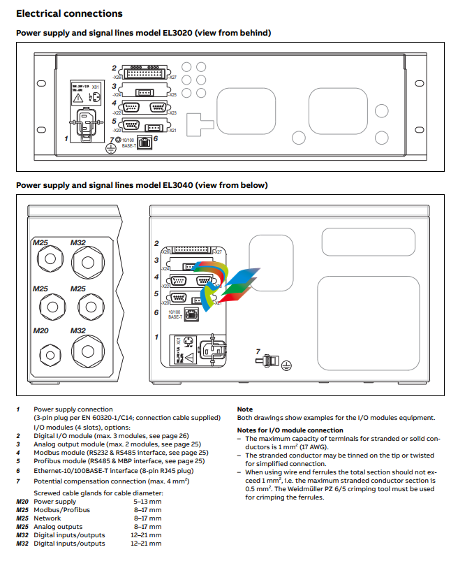
The electrical interfaces for the output of measured values and communication with external systems include
• The integrated Ethernet-10/100BASE-T interface for – gas analyzer configuration with configuration software ECT – QAL3 data transfer if the QAL3 monitoring option is integrated in the gas analyzer – data transmission with Modbus TCP/IP protocol (measured values, status signals and control signals) as well as the integrated I/O modules depending on the functional range and order Profibus module with one RS485 and one MBP interface (also according to VDI 4201 Part 2), Modbus module with one RS485 and one RS232 interface (also according to VDI 4201 Part 3), Digital I/O module with four digital inputs and four digital outputs, 2-way analog output module with two analog outputs, 4-way analog output module with four analog outputs.
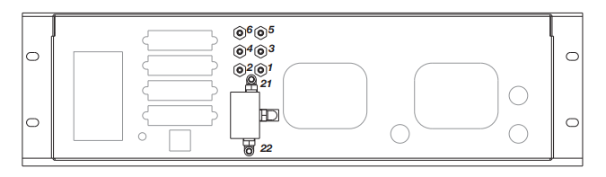
Integral gas feed
The integral gas feed (optional in model EL3020) is available in two versions. It includes
• either the solenoid valve, pump, coarse filter, capillary tube and flow sensor modules
• or a flow sensor module.
Housing design
The housing for the EL3020 gas analyzer model is designed as
19-inch housing with 3 height units (4 height units with Magnos27)
and degree of protection IP20 (IP40 with version for emission
monitoring).
The housing for the EL3040 gas analyzer model is designed as
wall-mount housing with degree of protection IP65.
Dynamic response
Warm-up time
Approx. 30 minutes without thermostat; approx. 2 hours with
thermostat
90% response time T90 ≤ 2.5 sec for sample gas flow = 60 l/h and electronic T90 time (static/dynamic) = 5/0 sec
Calibration
Zero-point calibration With inert gas, e.g. nitrogen, or with ambient air that is free of the sample component. End-point calibration With gas-filled calibration cells (optional) or with test gas mixtures. It is recommended to verify the calibration cell set values once a year.
Materials in contact with the sample medium
Analyzer (sample cells)
Tubing: aluminum; windows
Tubing: aluminum; windows: CaF2 or BaF2; connectors: stainless
steel 1.4305 (SAE 303)
Gas lines and connectors
Gas lines: FPM hoses or PTFE tubes; connectors: stainless steel
1.4305 (SAE 303); solenoid valve (option in model EL3020): PVDF.
When flammable components are present in the sample gas:
Gas lines: stainless steel tubes 1.4571 (SAE 316Ti); connectors:
stainless steel 1.4305 (SAE 303).
Gas connections
See page 27 and page 28
Sample gas inlet conditions
The analyzer must not be used for measurement of ignitable
gas/air or gas/oxygen mixtures.
Temperature
The sample gas dew point should be at least 5 °C below the temperature throughout the sample gas path. Otherwise a sample gas cooler or condensate trap is required.
Pressure
The analyzer is operated under atmospheric pressure; the sample gas outlet is open to atmosphere. Internal pressure drop < 5 hPa with standard flow rate 60 l/h. Permissible absolute pressure range: 800–1250 hPa. Operation under lower absolute pressure (e.g. at altitudes above 2000 m) on request. Overpressure in the sample cell max. 500 hPa.
Flow rate
20–100 l/h
Corrosive gases
Highly corrosive associated gas components, e.g. chlorine (Cl2)
and hydrogen chloride (HCl), as well as gases or aerosols containing chlorine must be cooled or undergo prior absorption.
Flammable gases
In the version with gas lines and connectors made of stainless
steel the analyzer is suitable for measuring flammable gases in
general purpose environment (see page 22).
Dynamic response
Warm-up time
< 1 hour
90% response time
T90 approx. 4 sec at a sample gas flow of 90 l/h and electronic
T90 time (static/dynamic) = 3/0 sec, gas change from nitrogen
to air
Calibration
Zero-point calibration
With oxygen-free process gas or substitute gas
End-point calibration
With process gas with a known oxygen concentration or a substitute gas such as dried air
Single-point calibration
Zero-point calibration with any oxygen concentration, e.g. with
nitrogen or ambient air, processed through a cooler or H2O absorber.
Pressure correction by means of pressure sensor is recommended for single-point calibration with air.
Depending on the measurement task involved, the zero- and endpoints should be verified periodically (recommendation: once a
year).
Calibration of measurement ranges with suppressed zero-point
Highly suppressed measurement ranges (≥95–100 vol.% O2)
should only be calibrated with test gases with concentrations in
the selected measurement range.
Materials in contact with the sample medium
Analyzer
Sample chamber (direct connection): stainless steel 1.4305
(SAE 303), glass, platinum, rhodium, epoxy resin; seals: FPM (Fluorocarbon rubber), PEEK, FFKM
Gas connectors of the solenoid valve (option in model EL3020)
PVDF
Gas connections
See page 30
Sample gas inlet conditions
The analyzer must not be used for measurement of ignitable
gas/air or gas/oxygen mixtures.
Temperature
The sample gas dew point should be at least 5 °C below the temperature throughout the sample gas path. Otherwise a sample
gas cooler or condensate trap is required. Water vapor content
variations cause volume errors.
Pressure
Operation under atmospheric pressure: The sample gas outlet is
open to atmosphere. Internal pressure drop < 5 hPa with standard flow rate 60 l/h. Permissible absolute pressure range: 800–
1250 hPa. Operation under lower absolute pressure (e.g. at altitudes above 2000 m) on request.
Operation under elevated pressure: A pressure sensor is required
for pressure influence compensation.
Absolute pressure ≤ 1250 hPa: An optional internal pressure sensor can be connected to the sample gas path.
Absolute pressure ≥ 1250 hPa: An external pressure sensor must
be connected to the sample gas path.
The analyzer is function-tested for 5000 hPa internal pressure
without damage.
Flow rate
30–90 l/h
Corrosive gases
Consultation with ABB Analytical is required if the sample gas
contains Cl2, HCl, HF or other corrosive components.
The AO2000-Magnos206 analyzer should be used if the sample
gas contains NH3.
Flammable gases
The analyzer is suitable for measuring flammable gases in general purpose environment (see page 22).
Oxygen analyzer Magnos28 Measurement principle Paramagnetic behavior of oxygen Magnetomechanical oxygen analyzer Sample component and measurement ranges Sample component Oxygen (O2) Smallest measurement range 0–2 vol.% O2 Measurement range quantity 2 measurement ranges Measurement range limits Measurement ranges are freely adjustable; they are factory-set per order to 0–5 vol.% O2 or 0–25 vol.% O2 or 0–100 vol.% O2 or 98–100 vol.% O2. Largest measurement range 0–100 vol.% O2 Measurement ranges should not be set within ignition limits. Measurement ranges with suppressed zero-point Suppressed measurement ranges are freely adjustable in the range 0–100 vol.% O2. Smallest span 2 vol.% O2. The combination of a suppressed and an initial measurement range is not possible. Pressure correction with a pressure sensor is required. A pressure sensor is installed when the analyzer has been ordered with suppressed measurement range. Stability The following data apply only if all influence factors (e.g. flow rate, temperature, atmospheric pressure) are constant. Linearity deviation ≤ 0.5 % of span, at least 0.005 Vol.-% O2 Repeatability ≤ 50 ppm O2 Zero drift ≤ 3 % of span of the smallest measurement range (per order) per week, minimum 300 ppm O2 per week Sensitivity drift ≤ 0.1 vol.% O2 per week or ≤ 1 % of measured value per week (not cumulative), whichever is smaller; ≤ 0.15 % of measured value per three months, minimum 0.03 vol.% O2 per three months Output fluctuation (2 σ) ≤ 25 ppm O2 at electronic T90 time (static/dynamic) = 3/0 sec Detection limit (4 σ) ≤ 50 ppm O2 at electronic T90 time (static/dynamic) = 3/0 sec Influence effects Flow effect ≤ 0.1 vol.% O2 in the 30–90 l/h range Associated gas effect Data regarding the effect of associated gases can be found in IEC 61207-3:2002 “Gas analyzers – Expression of performance – Part 3: Paramagnetic oxygen analyzers”. Temperature effect Ambient temperature in the permissible range – At zero-point: ≤ 0.02 vol.% O2 per 10 °C – On sensitivity: ≤ 0.3 % vol.% O2 per 10 °C Thermostat temperature = 60 °C Air pressure effect – On sensitivity with no pressure correction: ≤ 1 % of measured value per 1 % air pressure change – On sensitivity with pressure correction using integrated pressure sensor (optional): ≤ 0.1 % of measured value per 1 % air pressure change; for highly suppressed measurement ranges ≤ 0.01 % of measured value per 1 % air pressure change or ≤ 0.002 vol.% O2 per 1 % air pressure change, whichever is greater. Power supply effect DC 24 V ± 5 %: within detection limit Position effect Zero-point shift ≤ 0.05 vol.% O2 per 1° deviation from horizontal orientation. Position has no effect on the hard-mounted unit.
Dynamic response Warm-up time < 1 hour 90% response time T90 ≤ 3 sec at a sample gas flow of 90 l/h and electronic T90 time (static/dynamic) = 3/0 sec, gas change from nitrogen to air (see “Gas connections”, applies to an analyzer unit only with Magnos28) Calibration Zero-point calibration With oxygen-free process gas or substitute gas End-point calibration With process gas with a known oxygen concentration or a substitute gas such as dried air Single-point calibration Zero-point calibration with any oxygen concentration, e.g. with nitrogen or ambient air, processed through a cooler or H2O absorber. Pressure correction by means of pressure sensor is recommended for single-point calibration with air. Depending on the measurement task involved, the zero- and endpoints should be verified periodically (recommendation: once a year). Calibration of measurement ranges with suppressed zero-point Highly suppressed measurement ranges (≥95–100 vol.% O2) should only be calibrated with test gases with concentrations in the selected measurement range. Single-point calibration can also be done within a suppressed measurement range. The O2 concentration of the test gas must lie within the measurement range. Materials in contact with the sample medium Analyzer Stainless steel 1.4305 (SAE 303), nickel alloy, glass, PtNi, silicon, gold, PTFE; FPM seals, optional: FFKM75 Gas connectors of the solenoid valve (option in model EL3020) PVDF Gas connections See page 31 Sample gas inlet conditions The analyzer must not be used for measurement of ignitable gas/air or gas/oxygen mixtures. Temperature The sample gas dew point should be at least 5 °C below the temperature throughout the sample gas path. Otherwise a sample gas cooler or condensate trap is required. Water vapor content variations cause volume errors. Pressure The analyzer is operated under atmospheric pressure; the sample gas outlet is open to atmosphere. Internal pressure drop < 5 hPa with standard flow rate 60 l/h. Permissible absolute pressure range: 800–1250 hPa. Operation under lower absolute pressure (e.g. at altitudes above 2000 m) on request. Operation under elevated pressure: A pressure sensor is required for pressure influence compensation. Absolute pressure ≤ 1250 hPa: An optional internal pressure sensor can be connected to the sample gas path. Absolute pressure ≥ 1250 hPa: An external pressure sensor must be connected to the sample gas path. Correction is done externally. Flow rate 30–90 l/h Changes of the sample gas flow rate should be avoided in highly suppressed measurement ranges. Corrosive gases Consultation with ABB Analytical is required if the sample gas contains Cl2, HCl, HF or other corrosive components. FFKM75 seals must be used if the sample gas contains NH3. In this case the integral gas feed cannot be connected to the analyzer. The pressure sensor must not be connected to the sample gas path. Flammable gases The analyzer is suitable for measuring flammable gases in general purpose environment (see page 22).
Oxygen analyzer Magnos27 Measurement principle Paramagnetic behavior of oxygen Heavy-duty thermomagnetic analyzer Sample component and measurement ranges Sample component Oxygen (O2) in flue gas or in nitrogen (N2) Smallest measurement range 0–10 vol.% O2 Measurement range quantity 2 measurement ranges Measurement range limits The measurement range is factory-set per customer order. Largest measurement range 0–100 vol.% O2 Measurement ranges within ignition limits cannot be provided. Stability Linearity deviation ≤ 2 % of span Repeatability ≤ 1 % of span Zero drift ≤ 1 % of span per week Sensitivity drift ≤ 2 % of measured value per week Output fluctuation (2 σ) ≤ 0.5 % of smallest measurement range span at electronic T90 time = 0 sec Detection limit (4 σ) ≤ 1 % of smallest measurement range span at electronic T90 time = 0 sec Influence effects Flow effect ≤ 1 % of span at a flow change of ±10 l/h. At an identical flow rate for test and sample gases the flow rate effect is automatically compensated. Associated gas effect Magnos27 calibration applies only to the sample gas shown on the identification plate (= sample component + associated gas). Temperature effect Ambient temperature in permissible range – At zero-point: ≤ 2 % of span per 10 °C – On sensitivity: ≤ 0.5 % of measured value per 10 °C relative to temperature at the time of calibration Thermostat temperature = 63 °C Air pressure effect – At zero-point: < 0.05 vol.% O2 per 1 % air pressure change – On sensitivity without pressure correction: ≤ 1.5 % of measured value per 1 % air pressure change – On sensitivity with pressure correction using integrated pressure sensor (optional): ≤ 0.25 % of measured value per 1 % air pressure change Option: Operating altitude over 2000 m Power supply effect DC 24 V ± 5 %: ≤ 0.2 % of span Position effect Approx. 3 % of smallest measurement range span per 1° deviation from horizontal orientation. Position has no effect on the hardmounted unit.
Dynamic response Warm-up time 2–4 hours 90% response time T90 = 10–22 sec, depending on sample gas flow and on measurement cell connection (see “Gas connections”, applies to an analyzer unit only with Magnos27) Calibration Zero-point calibration With oxygen-free process gas or substitute gas End-point calibration With process gas having a known oxygen concentration or with substitute gas Materials in contact with the sample medium Analyzer Rust- and acid-resistant steel 1.4580 (SAE 316Cb) and 1.4305 (SAE 303), glass Gas lines and connectors Rust- and acid-resistant steel 1.4571 (SAE 316Ti) and 1.4305 (SAE 303), PVC-C, FPM Gas connections See page 32 Sample gas inlet conditions The analyzer must not be used for measurement of flammable gases and ignitable gas/air or gas/oxygen mixtures. Temperature The sample gas dew point should be at least 5 °C below the temperature throughout the sample gas path. Otherwise a sample gas cooler or condensate trap is required. Water vapor content variations cause volume errors. Pressure The analyzer is operated under atmospheric pressure; the sample gas outlet is open to atmosphere. Internal pressure drop < 5 hPa with standard flow rate 60 l/h. Permissible absolute pressure range: 800–1250 hPa. Operation under lower absolute pressure (e.g. at altitudes above 2000 m) on request. Overpressure in the sample cell max. 100 hPa. Flow rate 20–90 l/h Note The analyzer can only be mounted in the 19-inch housing (dimensional drawing see page 32). The analyzer cannot be used in combination with the integral gas feed.
Trace oxygen analyzer ZO23
Measurement principle
Potentiometric measurement; zirconium dioxide cell for determination of the oxygen concentration in accordance with Nernst’s
equation; reference gas: ambient air.
The analyzer is used for the continuous measurement of oxygen
in pure gases (N2, CO2, Ar). The measuring cell is catalytically inactivated to the extent that flammable carrier components in stoichiometric concentrations only negligibly reduce the oxygen
value.
Sample component and measurement ranges
Sample component
Oxygen (O2)
Measurement range quantity
2 measurement ranges
Measurement range limits
Measurement ranges are freely adjustable within the range
0–1 ppm to 0–250,000 ppm O2; they are factory-set to
0–1/0–10 ppm O2.
The following measurement data refer to a measurement span of
100 ppm O2 with a regulated flow rate of 8 ± 0.2 l/h.
Stability
Linearity
Owing to the measurement principle, zirconium dioxide cells are
base linear.
Repeatability
< 1 % of the measurement range or 100 ppb O2 (whichever is
greater)
Zero drift
The zero point (reference point) is displayed if ambient air is present on the sample gas side. The value for air of 20.6 % vol. of O2
(for 25 °C and 50 % relative humidity) may deviate through aging
of the cell.
< 1 % of the measurement range per week or 250 ppb O2 (whichever is greater)
Sensitivity drift
Depends on possible interfering components (catalyst poisons)
in the sample gas and the aging of the cell.
For pure gas measurements in N2 and Ar:
< 1 % of the measurement range per week or 250 ppb O2 (whichever is greater)
Output fluctuation (2 σ)
< ±0.5 % of the measured value or 50 ppb O2 (whichever is
greater)
Influence effects
Flow effect
≤ 300 ppbv O2 in the permissible range
Associated gas effect
Inert gases (Ar, CO2, N2) have no effect. Flammable gases (CO, H2,
CH4) in stoichiometric concentrations to the oxygen content:
Conversion of O2 < 20 % of the stoichiometric conversion. If
higher concentrations of flammable gases are present, higher O2
conversions must be expected. The concentration of flammable
gases in the sample gas must not exceed 100 ppm.
Temperature effect
The effect of the ambient temperature in the permissible range
of +5 to +45 °C is < 2 % of the measured value or 50 ppb O2 per
10 °C change in the ambient temperature (whichever is greater).
Air pressure effect
No effect through a change in air pressure; the sample gas must
flow out of the outlet without back pressure.
Power supply effect
DC 24 V ± 5 %: no effect
Position effect
No position effect for permanently installed instruments
Pressure sensor
Use
Standard: with Uras26, Limas23, Caldos27,
Option: with Magnos206, Magnos28 and Magnos27
Working range
pabs = 600–1250 hPa
Materials in contact with the sample medium
Silicone gel, plastics, FPM (Fluorocarbon rubber)
Sample gas composition
The pressure sensor must not be connected to the sample gas
path when the sample gas is corrosive, flammable or explosive.
Fine filtration
Version
Disposable filter with borosilicate glass microfiber filter element
(supplied as accessory)
Retention rate
99.99 % for particles > 0.1 µm
Materials in contact with the sample medium
Polyamide, borosilicate glass with PVDF binder
Safety
Tested per EN 61010-1:2010
Protection class I
Overvoltage category/pollution degree
II/2
Safe isolation
The power supply is galvanically isolated from other circuits by
means of reinforced or double insulation. Protective extra-low
voltage (PELV) on low-voltage side
Electromagnetic compatibility
Noise immunity
Tested to EN 61326-1:2013. Inspection severity: Industrial area,
fulfills at least the test requirements to table 2 of EN 61326.
Emitted interference
Tested to EN 61326-1:2013. Limit value class B for interference
field strength and interference voltage is met.
Mechanical stress
Operation
Vibration test to EN 60068-2-6:1996
In Uras26, slight transient effects on the measured value can occur in the region of the modulation frequency.
Transport
Vibration test to EN 60068-2-6:1996,
shock test to EN 60068-2-27:1995
In its original packaging, the gas analyzer will withstand normal
shipping conditions.
Installation site requirements
Installation location
The gas analyzer is intended for indoor installation only. Installation location altitude max. 2000 m above sea level (over 2000 m
on request)
Ambient temperature
Operation: +5 to +45 °C, Uras26 in combination with another analyzer, Limas23, Fidas24: +5 to +40 °C, Storage and transport:
−25 to +65 °C
Relative humidity
< 75 %, slight condensation allowed
Air circulation
For sufficient air circulation, multiple housings in a 19-inch rack
must be installed with a separation of at least one height unit between housings.
Power supply
Input voltage
AC 100 to 240 V − 15/+ 10 %, 50 to 60 Hz ± 3 Hz
Power consumption
Max. 187 VA
Connection
3-pin plug per EN 60320-1/C14; connection cable supplied.
Connection diagrams see page 24.
Individual analyzers
Input voltage
DC 24 V ± 5 %
Power consumption
Uras26: max. 95 W Magnos27: max. 35 W
Limas23: max. 100 W ZO23: max. 35 W
Magnos206: max. 50 W Caldos27: max. 17 W
Magnos28: max. 50 W Fidas24: max. 40 W
Fidas24: Heating of detector and sample gas inlet
Input voltage
AC 115 V or 230 V, ± 15 % (max. 250 V), 47 to 63 Hz
Power consumption
125 VA for detector heating,
125 VA for heated sample gas inlet (option)
Connection
4-pin plug; connection cable supplied.
Connection diagrams see page 35.
Note regarding the analyzers performance characteristics
The performance characteristics of the analyzers have been determined according to IEC 61207-1:2010 “Expression of performance of gas analyzers – Part 1: General”. They are based on operation at atmospheric pressure (1013 hPa) and nitrogen as the
associated gas. Compliance with these characteristics when
measuring other gas mixtures can only be assured if their composition is known. The physical detection limit is the lower limit
of the performance characteristics relative to the measuring
range span.
-
 AEROTECH SM Series High-Performance Stepper Motors
 -
 AEROTECH BLMSC Series Linear Motors
 -
 AEROTECH Custom Linear Motors
 -
 AEROTECH BMS Series Brushless, Slotless Rotary Motors
 -
 AEROTECH BM Series Brushless Rotary Motors
 -
 AEROTECH BLMX Series Linear Motors
 -
 AEROTECH BLMH Series Linear Motors
 -
 AEROTECH BLM Series Linear Motors
 -
 AEROTECH BLMC Series Linear Motors
 -
 AEROTECH BLMUC-143 Linear motor forcer with thermistor
 -
AEROTECH BLMUC-111 Linear motor forcer with thermistor
-
AEROTECH BLMUC-95 Linear motor forcer with thermistor
-
AEROTECH BLMUC-79 Linear motor forcer with thermistor
-
AEROTECH BLMUC Series Linear Motors
-
 AEROTECH Automation1 FLEX Distributed Amplifier Multi-Axis Servo Control System
 -
 AEROTECH Automation1 HXA4 6-Axis Hexapod Servo Drive
 -
 AEROTECH Automation1 iHXA4 6-Axis Hexapod Servo Drive with Motion Controller
 -
 AEROTECH Modular System Control Console
 -
 AEROTECH TV Series Transformers
 -
 AEROTECH TM Series Transformers
 -
 AEROTECH UFM Noise Filter Module
 -
 AEROTECH MFM Motor Filter Module
 -
 AEROTECH MPG Handwheel Pendant
 -
 AEROTECH Automation1 Multi-Axis Joystick
 -
 AEROTECH ETM Enhanced Throughput Module
 -
 AEROTECH Automation1 XL4s High-Speed, Single-Phase Linear Servo Drive
 -
 AEROTECH Automation1 XL2e Enhanced, Compact Linear Servo Drive
 -
 Automation1 iXL2e Enhanced, Compact Linear Servo Drive with Motion Controller
 -
 AEROTECH Automation1 XL5e Enhanced, Linear Servo Drive
 -
 AEROTECH Automation1 iXL5e Enhanced Linear Servo Drive with Motion Controller
 -
 AEROTECH Automation1 GI4 Laser Scan Head Controller
 -
 AEROTECH Automation1 SI4 Stepper Interface
 -
AEROTECH Automation1 XI4 Servo Interface
-
 AEROTECH AEROTECH Automation1 iXI4 Servo Interface with Motion Controller
 -
 AEROTECH Automation1 XC6e Enhanced, High-Power PWM Servo Drive
 -
 AEROTECH Automation1 iXC6e Enhanced, High-Power PWM Servo Drive with Motion Controller
 -
 AEROTECH Automation1 XC2 Compact PWM Servo Drive
 -
 AEROTECH Automation1 XC4 PWM Servo Drive
 -
 AEROTECH Automation1 GL4 Galvo Laser Scan Head Linear Drive
 -
 AEROTECH Automation1 XC2e Enhanced, Compact Servo Drive with PWM+
 -
 AEROTECH Automation1 XC4e Enhanced, PWM Servo Drive
 -
 AEROTECH Automation1 XR3 Multi-Axis Servo Drive Rack
 -
 AEROTECH Automation1 iXR3 Multi-Axis Servo Drive Rack with Motion Controller
 -
 AEROTECH Automation1 iXC2 Compact PWM Servo Drive with Motion Controller
 -
 AEROTECH Automation1 iXC2e Enhanced, Compact PWM+ Servo Drive with Motion Controller
 -
 AEROTECH Automation1 iXC4 PWM Servo Drive with Motion Controller
 -
 AEROTECH Automation1 iXC4e Enhanced, PWM Servo Drive with Motion Controller
 -
 AEROTECH Automation1 iPC Industrial PC with Motion Controller
 -
 AEROTECH EPICS & TANGO Drivers for Distributed Control Systems
 -
 AEROTECH .NET, C, Python & LabVIEW APIs Custom Application Develotpmen
 -
 AEROTECH Automation1 Industrial Ethernet Support
 -
 AEROTECH Automation1 iSMC Intelligent, Software-Based Motion Controller
 -
 AEROTECH Automation1 iXA4 1- 2- or 4-Axis PWM Servo Drive with Motion Controller
 -
 AEROTECH Automation1 XA4 1- 2- or 4-Axis PWM Servo Drive
 -
 CTI 2500-ADP2-DISC Discrete Wiring Adapter for Series 500
 -
 CTI 2500-ADP1 Analog Wiring Adapter for Series 500
 -
 CTI 2500C-RADP-RS485 Remote Base Controller Adapter for Series 500
 -
 CTI 2500C-RADP-RBC Profibus RBC Adapter for Series 500
 -
 CTI 2500C-PADP-120V 120VAC 50W Power Supply for Series 500
 -
 CTI 2500-RADP RBC Adapter for Series 500
 -
 CTI 2500-R4500 520/530/DBC Adapter for Series 500 - MATURE
 -
 CTI 2500-PADP Power Supply Adapter for Series 500
 -
 CTI 2500-IADP I/O Adapter for Series 500
 -
 CTI 2500-VP15A-N4-W7 15" Flat-Panel PC with Windows® 7 Embedded
 -
 CTI 2500S-27-1750 Slice I/O, Ethernet, RS232/485. 900MHz, 2DIO / 4UAI / 2AI
 -
 CTI 2500S-26-1750 Slice I/O, Ethernet, RS232/485. 900MHz, 8DIO / 2UAI
 -
 CTI 2500S-23-1750 Slice I/O, Ethernet, RS232/485. 900MHz, 4DI / 4DO / 2UAI / 2AO
 -
 CTI 2500S-27-1550 Slice I/O, RS232/485. 2DIO / 4UAI / 2AI
 -
 CTI 2500S-26-1550 Slice I/O, RS232/485. 8DIO / 2UAI
 -
 CTI 2500S-23-1550 Slice I/O, RS232/485. 4DI / 4DO / 2UAI / 2AO
 -
 CTI 2500S-27-1050 Slice I/O, Ethernet, 2DIO / 4UAI / 2AI
 -
 CTI 2500S-26-1050 Slice I/O, Ethernet, 8DIO / 2UAI
 -
 CTI 2500S-23-1050 Slice I/O, Ethernet, 4DI / 4DO / 2UAI / 2AO
 -
 CTI 2500C-32F-CJC 32-Pin Field Wiring Connector with Cold Junction Compensation
 -
 CTI 2500C-32F 32-Pin Field Wiring Connector
 -
 CTI 2500C-8-TC Eight Thermocouple Inputs
 -
 CTI 2500C-8-RTD Eight RTD Inputs
 -
 CTI 2500C-8-RL-FC 8 Form-C Relay Outputs
 -
 CTI 2500C-8-IDO-24V 8 Isolated 24VDC Outputs
 -
 CTI 2500C-8-IDO-120V 8 Isolated 120VAC Outputs
 -
 CTI 2500C-16-DO-24V Sixteen 24VDC Digital Outputs
 -
 CTI 2500C-16-DO-120V Sixteen 120VAC Digital Outputs
 -
.png) CTI 500C-16-IDI-24V Sixteen Isolated 24V AC/DC Digital Inputs
CTI 500C-16-IDI-24V Sixteen Isolated 24V AC/DC Digital Inputs -
 CTI 2500C-16-IDI-120V Sixteen Isolated 120V AC/DC Digital Inputs
 -
 CTI 2500C-16-DIDO-SIM Sixteen Digital Input and Output SImulator
 -
 CTI 2500C-16-DI-24V Sixteen 24V AC/DC Digital Inputs
 -
 CTI 2500C-16-DI-120V Sixteen 120V AC/DC Digital Inputs
 -
 CTI 2500C-RBC-RS485 RS485 Remote Base Controller
 -
 CTI 2500C-RBC-PRF Profibus Remote Base Controller
 -
 CTI 2500C-PS-24V-35 35-Watt DC Power Supply
 -
 CTI 2500C-PS-120V-35 35-Watt AC Power Supply
 -
 CTI 2500C-R8 Eight-Slot Base
 -
 CTI 2500C-R4 Four-Slot Base
 -
 CTI 2500C-R16 Sixteen-Slot Base
 -
 CTI 2500C-2572-B Fast Ethernet TCP/IP Adapter
 -
 CTI 2500C-J750 Compact Janus PAC with 3MB Project Memory
 -
 CTI 2500C-C300 CPU with 512K User Memory
 -
 CTI 2500C-C200 CPU with 256K User Memory
 -
 CTI 2500C-C100 CPU with 128K User Memory
 -
 CTI 2500C-8-AO 8 Analog Outputs
 -
 CTI 2500C-8-AI 8 Analog Inputs
 -
 CTI 2559-FCAL Precision Calibration Connector
 -
 CTI 2559-FPC 40-Position Screw-Terminal Connector
 -
 CTI 2500-RFC PLC to RF Modem Cable
 -
 CTI 2500-40F 40-Position Standard Screw-Terminal Connector
 -
 CTI 2505 Vibration Sensor Interface Module
 -
 CTI 2554-A 4-Channel Isolated High Speed Counter Module
 -
 CTI 2553-A 2-Channel Mag Meter Input Module
 -
 CTI 2502 2-Channel High Speed Counter Input Module
 -
 CTI 2559-TC 8-Channel Thermocouple Input Module
 -
 CTI 2556-A 16-Channel Isolated Thermocouple Input Module
 -
 CTI 2556 16-Channel Isolated Thermocouple Input Module
 -
 CTI 2551-A 8-Channel Isolated Thermocouple Input Module
 -
 CTI 2559-RTD 8-Channel RTD Input Module
 -
 CTI 2557-A 16-Channel RTD Input Module
 -
 CTI 2557 16-Channel RTD Input Module
 -
 CTI 2552-A 8-Channel Isolated RTD Input Module
 -
 CTI 2534 8-Point Form-C Relay Output Module
 -
 CTI 2532 16-Point Form-A Relay Output Module
 -
 CTI 2531 32-Point Form-A Relay Output Module
 -
 CTI 2530 8-Point Form-C Relay Output Module
 -
 CTI 2562 8-Channel Analog Output Module
 -
 CTI 2560-A 8-Channel Isolated Analog Output Module
 -
 CTI 2501 8in/4out Analog Module
 -
 CTI 2558 8-Channel Analog Input Module
 -
 CTI 2555-A 16-Channel Analog Input Module
 -
 CTI 2550-A 8-Channel Isolated Analog Input Module
 -
 CTI 2599 8/16/32-Point AC Output Module


