
ABB ACV 700 Frequency Converters
 Chapter 1 - System Description
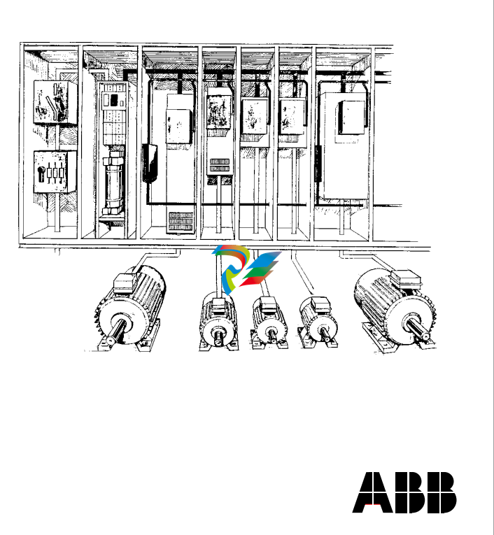
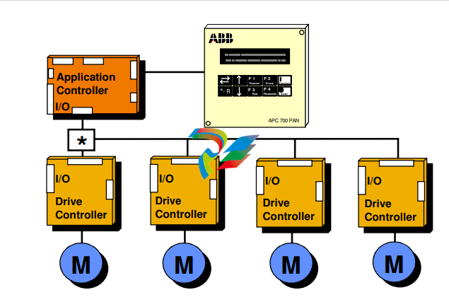
This manual describes the ACV 700 drive system to the application engineers and other persons involved with ACV 700. The drive has a multidrive configuration. It consists of a supply section including connection devices (main fuses and main contactor or circuit breaker), rectifier devices (a diode or thyristor bridge), capacitors for smoothing of the DC voltage, optional devices, if specified, and a number of drive sections. The power range for the supply sections is 40 - 2500 kVA and the power range for the drive sections is 9 - 2500 kVA. Depending on the required power and voltage, the drive sections are based on either an IGBT or GTO thyristor power stage. The control system is implemented by using the Common Drive Control, CDC, and the Digital Drive Control, DDC. The basic part of the CDC is the Application Controller, the APC. The APC is designed to give a flexible, compact and efficient system for controlling AC or DC drives. The APC is programmable by using function blocks. The DDC performs the inverter control functions. Programming can be done using two alternative tools, the Function Chart Editor, FCE or the AdvaBuild for Windows, the Drives version. Various drive configurations are possible using one or multiple APCs and their communication capabilities. In small systems one APC is connected to up to four Digital Drive Controllers (DDC). The drive configuration can be used in master/ follower applications when the master drive is of moderate complexity and the followers fairly simple. A consequence of multiplexing is that the performance of the drive controller interface decreases.
 System Description
Figure 1 - 1 Small drive system. In distributed multicontroller systems, several
APCs are interconnected by Advant Fieldbus 100 (AF100). Common control
functions can be distributed to separate nodes. No overriding automation
system is used in this configuration, but one or several application controllers
can communicate with external systems over communication boards. A personal
computer (PC) can be connected through one of the APCs and can be used for tool functions.
The concept of the control system is called Common Drive Control, CDC. The standard control functions of the drive section, such as speed and torque control, are located in the Digital Drive Controller, DDC. The application dependent control functions are located in the Application Controller, APC. Typical APC functions are section start and stop logic, internal and external interlocking, speed reference chain, load share control, drive-specific settings, logger functions, and system communication. Function blocks can be combined to macro blocks, which can perform application specific tasks such as crane control, lever control, remote panel control, etc. Each APC can control up to four DDCs. The APC is usually located in the drive section. The APC communicates with other APCs and with the centralised operator control devices via the AF100 communication bus. The APC and the DDC communicate via an optic fibre link. If the solution includes more than one DDC, an optic distributor board is
APC is designed to give a flexible, compact and efficient system for controlling AC- and DC-drives. APC is programmed by using function blocks. APC can be supplied with unstable + 24 VDC voltage (connector X1) that can vary in the range 19 - 30 VDC. Maximum input power consumption is 15 VA (0.63 A at 24 VDC). This power consumption includes 2 optional communication boards. APC can handle power supply failure with max. duration of 5 ms (i.e. voltage is below 19 V). When the APC board is slid into the CDC board rack, a 64 pole parallel bus (connector X8) on APC slides into the CDC board rack bus connector. AdvantFieldBus 100 (AF 100) is a high speed serial bus (connector X6), which is used for communication between APCs or between an APC and an overriding system such as ABB's MasterPiece 90. The communication board YPK 112A is used to connect the APC to the AF 100. RS-485 bus, a 8 pole screw terminal connector X2, is a low speed serial bus, which is used to connect remote I/O devices and control panels to the APC. Also other APCs can be connected to each other via this bus. The bus has to be grounded at one point to the same ground as the APC. Maximum length of the bus is 300 m. PC-Link, a standard 9 pole female D-connector X4, can be used to connect a personal computer to the APC. Physical interface is a standard non isolated RS-232C (V24) without any handshaking signals. Recommended maximum length of the cable between APC and PC is 5 m. Drive link, an optic link, is used to connect the APC to an AC or a DC drive. Optical fibres are connected to receiver V32 and transmitter V33. Communication speed is 1.5 Mbps. Max. length of the fibre is 15 m with standard attenuation cable (Hewlett-Packard HFBR-R or equivalent) and 25 m with extra low attenuation cable (HewlettPackard HFBR-E or equivalent). For standard I/O signals there is a 26-pole ribbon cable, connector X3, on APC. A separate terminal block board SNAT 602 TAC is always needed for field signal connections. The ribbon cable should be made as short as possible. Unshielded ribbon cable can be used provided that the cable is not longer than 2 m.
Jumper settings on SNAT 602 TAC: The jumper settings have no effect when the terminal block board is used with the APC.
Code: 3AFE 61041320 Bare panel Code: 3AFE 61068171 Incl. APC 700 PPW board
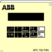
The control panel provides the following information and functions: - Status information (run, ready, fault messages)
- Operational control with 4 freely programmable pushbuttons - Display of reference values (speed, torque) - Display
of actual values (speed, voltage, current) - Display of fault logger contents - Uploading, downloading, changing, displaying
and saving the APC and DDC parameters. It can be used to control up to four DDCs one by one, depending on the application
program. Panel functions are freely programmable. The 9 VDC external power is supplied by the door panel Power Supply Board
APC 700 PPW. Dimensions of the panel are (w x h x d) 125 x 120 x 20 mm. Code: 3AFE 61064770 The door panel power supply
board is used to create the 9 VDC auxiliary voltage needed for the APC 700 PAN. The board is connected directly to the door panel
phone jack type connector by means of a male/male connecting piece. The board needs external 24 VDC power supply. Max.
current is 200 mA. A shielded signal cable from the APC is connected to connector X1. If the solution has several door panels
with one APC, the signal cable can be distributed from connector X1 to connector X1 on the next power supply board. The
The board is a general purpose I/O-board for connecting field signals to APC. It can be used as an extended or remote I/O-board.
The terminal board is always needed with the board because connection to the board is made with a ribbon cable. When the boa
rd is used as an extended I/O-board, it is slid into the CDC board rack and a 64-pole parallel bus connector X1 on the YPQ 111A s
lides into the CDC board rack bus connector. APC board is connected in the same way with the connector X8 to the parallel bus. Th
e 24 VDC power supply for the board is delivered by the parallel bus flat cable. Power consumption is 5 VA (0.2 A at 24 VDC). Peak
current with starting condition is 4 A. When the board is used as a remote I/O-board, it can be mounted anywhere and it is connec
ted to the YPP 110A via the low speed serial bus (RS-485). This configuration needs an external 24 VDC power supply and it is pow
ered via the connection card. Although the address for the board can be set to 0 - F (hex) with switch S1, the system software use
s only addresses 1 - 4 (hex) for the extended I/O-board. Because of this, only 4 extended I/O-boards can be connected to one APC.
Field signals can be connected to the YPQ 111A board via the YPT 111A or YPT 111B connection card. If no extra qualities for input
s and outputs are needeed, YPQ 111A can be used with the connection card UT86-2X40C
The Extended I/O Terminal Board YPT111A is used together with the Extended I/O Board YPQ111A. The Extended I/O Terminal YPT111A is connected to the Extended I/O Board YPQ111A with two 40-pin flat cables. Connection card YPT 111A is used for connecting the field instruments to YPQ111A. There are two separated power supply inputs for 24 VDC in the I/O terminal board YPT111A: +24V IN / BI for binary inputs (X1: pins 1,3,5,7) and +24V IN for YPQ111A when it is used as remote I/O (X1: pins 9,11,13,15). For chaining these voltage inputs from one YPT111A to another YPT111A or YPT111B there are 4 inputs for both the supplies. In the case of chaining one to three 24 VDC inputs will be used as outputs. Pins 9, 11, 13 and 15 of connector X1 should never be used if the I/O board YPQ111A is used as local I/O. The YPQ111A is then connected to the Application Controller YPP110A via the parallel back plane I/O connector and not via the serial bus
APC is designed to give a flexible, compact and efficient system for controlling AC- and DC-drives. APC is programmed by using function blocks. APC can be supplied with unstable + 24 VDC voltage (connector X1) that can vary in the range 19 - 30 VDC. Maximum input power consumption is 15 VA (0.63 A at 24 VDC). This power consumption includes 2 optional communication boards. APC can handle power supply failure with max. duration of 5 ms (i.e. voltage is below 19 V). When the APC board is slid into the CDC board rack, a 64 pole parallel bus (connector X8) on APC slides into the CDC board rack bus connector. AdvantFieldBus 100 (AF 100) is a high speed serial bus (connector X6), which is used for communication between APCs or between an APC and an overriding system such as ABB's MasterPiece 90. The communication board YPK 112A is used to connect the APC to the AF 100. RS-485 bus, a 8 pole screw terminal connector X2, is a low speed serial bus, which is used to connect remote I/O devices and control panels to the APC. Also other APCs can be connected to each other via this bus. The bus has to be grounded at one point to the same ground as the APC. Maximum length of the bus is 300 m. PC-Link, a standard 9 pole female D-connector X4, can be used to connect a personal computer to the APC. Physical interface is a standard non isolated RS-232C (V24) without any handshaking signals. Recommended maximum length of the cable between APC and PC is 5 m. Drive link, an optic link, is used to connect the APC to an AC or a DC drive. Optical fibres are connected to receiver V32 and transmitter V33. Communication speed is 1.5 Mbps. Max. length of the fibre is 15 m with standard attenuation cable (Hewlett-Packard HFBR-R or equivalent) and 25 m with extra low attenuation cable (HewlettPackard HFBR-E or equivalent). For standard I/O signals there is a 26-pole ribbon cable, connector X3, on APC. A separate terminal block board SNAT 602 TAC is always needed for field signal connections. The ribbon cable should be made as short as possible. Unshielded ribbon cable can be used provided that the cable is not longer than 2 m.
-
 AEROTECH SM Series High-Performance Stepper Motors
 -
 AEROTECH BLMSC Series Linear Motors
 -
 AEROTECH Custom Linear Motors
 -
 AEROTECH BMS Series Brushless, Slotless Rotary Motors
 -
 AEROTECH BM Series Brushless Rotary Motors
 -
 AEROTECH BLMX Series Linear Motors
 -
 AEROTECH BLMH Series Linear Motors
 -
 AEROTECH BLM Series Linear Motors
 -
 AEROTECH BLMC Series Linear Motors
 -
 AEROTECH BLMUC-143 Linear motor forcer with thermistor
 -
AEROTECH BLMUC-111 Linear motor forcer with thermistor
-
AEROTECH BLMUC-95 Linear motor forcer with thermistor
-
AEROTECH BLMUC-79 Linear motor forcer with thermistor
-
AEROTECH BLMUC Series Linear Motors
-
 AEROTECH Automation1 FLEX Distributed Amplifier Multi-Axis Servo Control System
 -
 AEROTECH Automation1 HXA4 6-Axis Hexapod Servo Drive
 -
 AEROTECH Automation1 iHXA4 6-Axis Hexapod Servo Drive with Motion Controller
 -
 AEROTECH Modular System Control Console
 -
 AEROTECH TV Series Transformers
 -
 AEROTECH TM Series Transformers
 -
 AEROTECH UFM Noise Filter Module
 -
 AEROTECH MFM Motor Filter Module
 -
 AEROTECH MPG Handwheel Pendant
 -
 AEROTECH Automation1 Multi-Axis Joystick
 -
 AEROTECH ETM Enhanced Throughput Module
 -
 AEROTECH Automation1 XL4s High-Speed, Single-Phase Linear Servo Drive
 -
 AEROTECH Automation1 XL2e Enhanced, Compact Linear Servo Drive
 -
 Automation1 iXL2e Enhanced, Compact Linear Servo Drive with Motion Controller
 -
 AEROTECH Automation1 XL5e Enhanced, Linear Servo Drive
 -
 AEROTECH Automation1 iXL5e Enhanced Linear Servo Drive with Motion Controller
 -
 AEROTECH Automation1 GI4 Laser Scan Head Controller
 -
 AEROTECH Automation1 SI4 Stepper Interface
 -
AEROTECH Automation1 XI4 Servo Interface
-
 AEROTECH AEROTECH Automation1 iXI4 Servo Interface with Motion Controller
 -
 AEROTECH Automation1 XC6e Enhanced, High-Power PWM Servo Drive
 -
 AEROTECH Automation1 iXC6e Enhanced, High-Power PWM Servo Drive with Motion Controller
 -
 AEROTECH Automation1 XC2 Compact PWM Servo Drive
 -
 AEROTECH Automation1 XC4 PWM Servo Drive
 -
 AEROTECH Automation1 GL4 Galvo Laser Scan Head Linear Drive
 -
 AEROTECH Automation1 XC2e Enhanced, Compact Servo Drive with PWM+
 -
 AEROTECH Automation1 XC4e Enhanced, PWM Servo Drive
 -
 AEROTECH Automation1 XR3 Multi-Axis Servo Drive Rack
 -
 AEROTECH Automation1 iXR3 Multi-Axis Servo Drive Rack with Motion Controller
 -
 AEROTECH Automation1 iXC2 Compact PWM Servo Drive with Motion Controller
 -
 AEROTECH Automation1 iXC2e Enhanced, Compact PWM+ Servo Drive with Motion Controller
 -
 AEROTECH Automation1 iXC4 PWM Servo Drive with Motion Controller
 -
 AEROTECH Automation1 iXC4e Enhanced, PWM Servo Drive with Motion Controller
 -
 AEROTECH Automation1 iPC Industrial PC with Motion Controller
 -
 AEROTECH EPICS & TANGO Drivers for Distributed Control Systems
 -
 AEROTECH .NET, C, Python & LabVIEW APIs Custom Application Develotpmen
 -
 AEROTECH Automation1 Industrial Ethernet Support
 -
 AEROTECH Automation1 iSMC Intelligent, Software-Based Motion Controller
 -
 AEROTECH Automation1 iXA4 1- 2- or 4-Axis PWM Servo Drive with Motion Controller
 -
 AEROTECH Automation1 XA4 1- 2- or 4-Axis PWM Servo Drive
 -
 CTI 2500-ADP2-DISC Discrete Wiring Adapter for Series 500
 -
 CTI 2500-ADP1 Analog Wiring Adapter for Series 500
 -
 CTI 2500C-RADP-RS485 Remote Base Controller Adapter for Series 500
 -
 CTI 2500C-RADP-RBC Profibus RBC Adapter for Series 500
 -
 CTI 2500C-PADP-120V 120VAC 50W Power Supply for Series 500
 -
 CTI 2500-RADP RBC Adapter for Series 500
 -
 CTI 2500-R4500 520/530/DBC Adapter for Series 500 - MATURE
 -
 CTI 2500-PADP Power Supply Adapter for Series 500
 -
 CTI 2500-IADP I/O Adapter for Series 500
 -
 CTI 2500-VP15A-N4-W7 15" Flat-Panel PC with Windows® 7 Embedded
 -
 CTI 2500S-27-1750 Slice I/O, Ethernet, RS232/485. 900MHz, 2DIO / 4UAI / 2AI
 -
 CTI 2500S-26-1750 Slice I/O, Ethernet, RS232/485. 900MHz, 8DIO / 2UAI
 -
 CTI 2500S-23-1750 Slice I/O, Ethernet, RS232/485. 900MHz, 4DI / 4DO / 2UAI / 2AO
 -
 CTI 2500S-27-1550 Slice I/O, RS232/485. 2DIO / 4UAI / 2AI
 -
 CTI 2500S-26-1550 Slice I/O, RS232/485. 8DIO / 2UAI
 -
 CTI 2500S-23-1550 Slice I/O, RS232/485. 4DI / 4DO / 2UAI / 2AO
 -
 CTI 2500S-27-1050 Slice I/O, Ethernet, 2DIO / 4UAI / 2AI
 -
 CTI 2500S-26-1050 Slice I/O, Ethernet, 8DIO / 2UAI
 -
 CTI 2500S-23-1050 Slice I/O, Ethernet, 4DI / 4DO / 2UAI / 2AO
 -
 CTI 2500C-32F-CJC 32-Pin Field Wiring Connector with Cold Junction Compensation
 -
 CTI 2500C-32F 32-Pin Field Wiring Connector
 -
 CTI 2500C-8-TC Eight Thermocouple Inputs
 -
 CTI 2500C-8-RTD Eight RTD Inputs
 -
 CTI 2500C-8-RL-FC 8 Form-C Relay Outputs
 -
 CTI 2500C-8-IDO-24V 8 Isolated 24VDC Outputs
 -
 CTI 2500C-8-IDO-120V 8 Isolated 120VAC Outputs
 -
 CTI 2500C-16-DO-24V Sixteen 24VDC Digital Outputs
 -
 CTI 2500C-16-DO-120V Sixteen 120VAC Digital Outputs
 -
.png) CTI 500C-16-IDI-24V Sixteen Isolated 24V AC/DC Digital Inputs
CTI 500C-16-IDI-24V Sixteen Isolated 24V AC/DC Digital Inputs -
 CTI 2500C-16-IDI-120V Sixteen Isolated 120V AC/DC Digital Inputs
 -
 CTI 2500C-16-DIDO-SIM Sixteen Digital Input and Output SImulator
 -
 CTI 2500C-16-DI-24V Sixteen 24V AC/DC Digital Inputs
 -
 CTI 2500C-16-DI-120V Sixteen 120V AC/DC Digital Inputs
 -
 CTI 2500C-RBC-RS485 RS485 Remote Base Controller
 -
 CTI 2500C-RBC-PRF Profibus Remote Base Controller
 -
 CTI 2500C-PS-24V-35 35-Watt DC Power Supply
 -
 CTI 2500C-PS-120V-35 35-Watt AC Power Supply
 -
 CTI 2500C-R8 Eight-Slot Base
 -
 CTI 2500C-R4 Four-Slot Base
 -
 CTI 2500C-R16 Sixteen-Slot Base
 -
 CTI 2500C-2572-B Fast Ethernet TCP/IP Adapter
 -
 CTI 2500C-J750 Compact Janus PAC with 3MB Project Memory
 -
 CTI 2500C-C300 CPU with 512K User Memory
 -
 CTI 2500C-C200 CPU with 256K User Memory
 -
 CTI 2500C-C100 CPU with 128K User Memory
 -
 CTI 2500C-8-AO 8 Analog Outputs
 -
 CTI 2500C-8-AI 8 Analog Inputs
 -
 CTI 2559-FCAL Precision Calibration Connector
 -
 CTI 2559-FPC 40-Position Screw-Terminal Connector
 -
 CTI 2500-RFC PLC to RF Modem Cable
 -
 CTI 2500-40F 40-Position Standard Screw-Terminal Connector
 -
 CTI 2505 Vibration Sensor Interface Module
 -
 CTI 2554-A 4-Channel Isolated High Speed Counter Module
 -
 CTI 2553-A 2-Channel Mag Meter Input Module
 -
 CTI 2502 2-Channel High Speed Counter Input Module
 -
 CTI 2559-TC 8-Channel Thermocouple Input Module
 -
 CTI 2556-A 16-Channel Isolated Thermocouple Input Module
 -
 CTI 2556 16-Channel Isolated Thermocouple Input Module
 -
 CTI 2551-A 8-Channel Isolated Thermocouple Input Module
 -
 CTI 2559-RTD 8-Channel RTD Input Module
 -
 CTI 2557-A 16-Channel RTD Input Module
 -
 CTI 2557 16-Channel RTD Input Module
 -
 CTI 2552-A 8-Channel Isolated RTD Input Module
 -
 CTI 2534 8-Point Form-C Relay Output Module
 -
 CTI 2532 16-Point Form-A Relay Output Module
 -
 CTI 2531 32-Point Form-A Relay Output Module
 -
 CTI 2530 8-Point Form-C Relay Output Module
 -
 CTI 2562 8-Channel Analog Output Module
 -
 CTI 2560-A 8-Channel Isolated Analog Output Module
 -
 CTI 2501 8in/4out Analog Module
 -
 CTI 2558 8-Channel Analog Input Module
 -
 CTI 2555-A 16-Channel Analog Input Module
 -
 CTI 2550-A 8-Channel Isolated Analog Input Module
 -
 CTI 2599 8/16/32-Point AC Output Module


