
Advant Controller 31 Series 40 and 50
1 Introduction
This chapter gives you an introduction to the AC31 automation, from the overall architecture to
the operational rules of the 40 and 50 series basic units
1.1 General information on the AC31 system
The AC31 system consists of the series 30, 40, 50, and 90. This operating manual describes the series 40 and 50.
The AC31 brings accessibility to beginners and experienced automation users alike, for any application with 14 to
approximately 1000 inputs / outputs and more, using the same set of basic components. From a compact machine
fitted with a few automated functions to large installations spread over hundreds of meter, and even kilometers, th
e AC31 can fit your requirements. It is therefore possible to realize distributed applications throughout a site, a wor
kshop, or a machine where each component (input / output units, basic unit) is close to the sensors / actuators. T
he whole setup is connected by a single twisted pair over which all information from the sensors is sent after proc
essing by the basic unit to the actuators via the remote modules. Additional central units configured as slave can
also be connected to this CS31 system bus. In case of the series 40 and 50 the following communication interface
s are available, to extend the AC31’s possibilities and integration with the company's other automation systems: M
ODBUS, ASCII, ARCNET, RCOM, AF100. The developments in this field are continua
Many users on all the continents have realized numerous applications such as:
Machine control:
- Manufacturing of floor boards
- Assembly of electrical contactors
- Manufacturing of ceramic products
Controlling-commanding installations:
- Wharf cranes
- Water treatment
- Ski lifts
- Wind power machines, etc.
System management:
- Climatic anagement
- Building power management
- Tunnel ventilation
- Alarms in hospital environments
- Greenhouse lighting / humidity, etc.
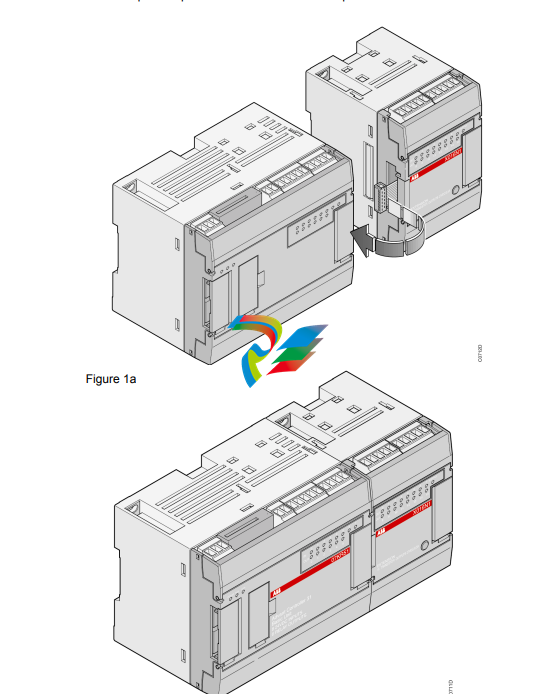
1.2 General set-up rules
An ABB AC31 system always includes at least one
AC31 basic unit. There are three types of basic un
its: - The 40 series basic unit, with a local interface
for central inputs / outputs extensions - The 50 ser
ies basic unit, with a local interface for central inpu
ts / outputs extensions and a CS31 system bus inter
face for decentralized extensions - The 90 series basi
c unit, with a CS31 system bus interface for decentrali
zed extensions Each basic unit incorporates a specific
number of digital inputs/outputs and in case of the
series 90 occasionally analog inputs/outputs. It is po
ssible, depending on the basic unit, to increase the
number of inputs / outputs, to add input / output e
xtensions connected directly to the basic units or re
mote input / output units via the CS31 twisted pair.
A master basic unit can manage up to 31 connection points, such as: - Series 50
remote units with central extension possibilities: a maximum of 6 extension units
comprising of e. g. a maximum of 8 analog input channels and 8 analog output c
hannels - Series 30 and 90 remote unit (without central extension possibilities) wi
th analog or digital inputs / outputs - An ABB NCSA-01 variable speed drive interfa
ce - A high-speed counter unit - 30, 50 and 90 series basic units as slave with the
ir own user program - Or any other device which supports CS31 communication. C
omment: A connection point fitted solely with digital channels occupies 1 connecti
on point. A connection point fitted with digital and analog channels occupies 2 con
nection points of the available 31. The maximum number of remote analog units d
epends on the MASTER basic unit: - 50 series: - a maximum of 31 remote analog i
nput units or - a maximum of 31 remote analog output units or - a maximum of 15
central extensible remote units (ICMK 14 ..) with analog input/output extensions +
1 remote analog input/output unit (15 x 2 + 1 = 31) or - a mixed digital/analog co
nfiguration within the previous limits - 90 series: - a maximum of 12 remote analog
input units or - a maximum of 12 remote analog output units or - a maximum of 1
-
 Beckhoff CP2918-0000 nelCP29xx-0000Pa | Multi-touch built-in Control Panel with DVI/USB Extended interface
 -
 Beckhoff CX2020-0122 Embedded PC Controller
 -
 Beckhoff C6640-0040 Control Cabinet Industrial PC 7-Slot
 -
 BECKHOFF CONTROL CABINET INDUSTRIAL PC - C6930-1062-0050
 -
 Beckhoff Automation EtherCAT Terminal EK1100 EK1122
 -
 Beckhoff CP6533-0001-0060 IPC
 -
 Beckhoff EK9500 | EtherNet/IP™ Bus Coupler
 -
 Beckhoff CP6202-1047-0050 - An industrial-grade embedded panel computer.
 -
 Beckhoff C6650-0040 Industrial PC
 -
 BECKHOFF CX5230-0185 / 000119805 PLC Module
 -
 BECKHOFF EL4732 | EtherCAT Terminal, 2-channel analog output, voltage, ±10 V, 16 bit, oversampling
 -
 Beckhoff CP6202-0001-0010 Economy Built-In Panel
 -
 Beckhoff AX5206-0000-0202 Digital Compact Servo Drives 2-channel
 -
 Beckhoff CP6606-0001-0020 7-inch Economy Panel PC
 -
 Beckhoff CPU basic module CX2020-0155 + power supply module CX2100-0004
 -
 Beckhoff CP2913-000 Multi-Touch Display
 -
 Beckhoff CP6500-1012-0060 14250369 Control Cabinet
 -
 Beckhoff CP7902-0001-0000 Economy Control Panel with DVI/USB Extended interface
 -
 Beckhoff C6920-0010 Control cabinet Industrial PC
 -
 BECKHOFF C3640-0050 Build-in Industrial PCs
 -
 Beckhoff KL6023-0000 KL6023 EnOcean Wireless-Adapter
 -
 Kollmorgen AKM54G-ANC2DB00 servo motor
 -
 Kollmorgen AKD-P00606-NBCN-0000 Servo Drive
 -
Kollmorgen S200 Series S20350-VTS SERVO DRIVE
-
 KOLLMORGEN AKD-P00606-NBCC-I000 SERVO DRIVE
 -
 Kollmorgen MV65WKS-CE310/22PB Servo Drive Control Module
 -
 Kollmorgen S20360-VTS-021 Servo Drive
 -
 KOLLMORGEN CR06550 High-precision digital servo amplifier
 -
 KOLLMORGEN DBL5N01050-03S-VV0-S40 3-Phase AC Synchronous Brushless Servo Motor
 -
 KOLLMORGEN S70301-NANANA-024 SERVO DRIVE
 -
 Kollmorgen S20360-VTS S200 Series Servo Drive
 -
 Kollmorgen RBE-03011-A00 Brushless Frameless Servo Motor
 -
 KOLLMORGEN AKD-T00306-NBAN-0000 INPUT SERVO DRIVE
 -
 KOLLMORGEN S700 Servo Controller S70302-NANANA
 -
 Kollmorgen AKD-P00607-NBEC-0000 400/480VAC 4.40KVA Servo Drive.
 -
 KOLLMORGEN S70102-NANANA SERVO DRIVE
 -
 KOLLMORGEN AKM21E-ANSNEH02 PM Servo Motor & PRD-AMPE25EB-00 Servo Drive Array
 -
 KollMorgen SC1R06260 Servo Drive 1.4/2.2 KVA 115230 Vac
 -
 Kollmorgen AKD-P00306-NBAN-0000 Servo Drive
 -
Kollmorgen TTB2-2042-3052-A DC Motor Industrial Drive 5.5A 185 oz/in
-
 KOLLMORGEN SERVOSTAR 610-AS SERVO AMPLIFIER_SERVOSTAR610AS_S61001
 -
 KOLLMORGEN PRD-0016400P-10 & PRD-0016600D-30 Axis Control System Modules
 -
KOLLMORGEN Seidel DBL5N01700-03S-000-S40 Servo Motor
-
 Hirschmann RS20-1600M2T1SDAEHH03.1.02 Rail Switch
 -
 Hirschmann BRS30-24TX Industrial Rail Switch
 -
 Hirschmann RSPM20-4T14T1EV9HHS999.9.99 Managed Ethernet Switch
 -
 Hirschmann BELDEN RS40-0009CCCCSDAPHH09.0.14 / RS400009CCCCSDAPHH09014
 -
Hirschmann RS40 Rail Switch RS40-0009CCCCSDAE
-
 Hirschmann BELDEN RS30-0802T1T1SDAP / RS300802T1T1SDAP Fully Managed Layer 2 Compact Rail Switch
 -
 Hirschmann BELDEN RS20-0800M2M2SDAUHH / RS200800M2M2SDAUHH
 -
 Hirschmann EAGLE30-04022O6TT999SCCY9HSE3F Industrial Firewall Router Switch
 -
 Hirschmann RS20-1600T1T1SDAEHH09.0.14 RS20 Rail Mount Ethernet Switch
 -
 Hirschmann EAGLE0200T1T1TDDY90000HHE05.3.03 Industrial Security Router
 -
Hirschmann - BELDEN MIPP-AD-1L9P
-
 HIRSCHMANN RSPM20-4Z64Z6TV9HHS9 942 106-999 RAIL SAFETY SWITCH
 -
 HIRSCHMANN FIBEROPTIC MODULE FIP P/N: OZDFIPG3T
 -
 HIRSCHMANN RS20-1600M2M2SDAUHH Ethernet rack-mounted switch
 -
 HIRSCHMANN BELDEN RS20-0400T1T1SDAEHH04.0.01 / RS200400T1T1SDAEHH04001
 -
HIRSCHMANN MM2-4FXM3 MICE Media Module
-
HIRSCHMANN RS20-0800M2M2SDAE Industrial Ethernet Rail Switch
-
 Hirschmann RS20-2400T1T1SDAP / RS20-2400T1T1SDAPHH05.0.02
 -
 GE MLJ1005B010H00C MLJ Digital Synchromism Check
 -
 ALSTOM MICROTECH DX21-M2 Digital Excitation Controller
 -
HIRSCHMANN BRS20-1200ZZZZ-STCY99HHSES
-
 HIRSCHMANN MM3-4FXM2 MICE Media Module
 -
Hirschmann RSB20-0800T1T1SAABHH 8Port ENet Rail Switch RSB20
-
 Hirschmann MACH102-8TP Ethernet Switch
 -
 SAACKE DDZ-M marine steam pressure atomizer
 -
 SAACKE SKV-A marine rotary cup atomizer
 -
 SAACKE Seavis HMI05e
 -
 Kollmorgen MMC-SD-2.0-230 Servo Drive 100-240VAC 2KW 10A Output 3PH 100-240VAC
 -
 Kollmorgen Servo drive CR10550
 -
 Kollmorgen AKD-P01207-NACN-0054 Servo Driver
 -
 Kollmorgen S406M-CA-036 Servostar
 -
.png) Kollmorgen AKD-B02407-NAAN-0000 Digital Servo Drive
Kollmorgen AKD-B02407-NAAN-0000 Digital Servo Drive -
 Kollmorgen SERVOSTAR S406AM-CA Digital Servo Drive
 -
 KOLLMORGEN SERVOSTAR 603-AS SERVO AMPLIFIER_SERVOSTAR603AS_S60301
 -
Kollmorgen S700 Servo Controller (S70602-NANANA-NA)
-
 Kollmorgen MPK411 controller
 -
 KOLLMORGEN MMC-SD-1.3-460-D Smart Drive
 -
 KOLLMORGEN AKM21C-CKB2AA-00 / AKM21CCKB2AA00 Servomotor
 -
 BECKHOFF AX5106-0000-0200 | Digital Compact Servo Drives 1-channel
 -
 BECKHOFF C3620-0000 INDUSTRIAL COMPUTER (MOTORSHELVES)
 -
 Beckhoff EK1960-0000 TwinSAFE Compact Controller
 -
 Beckhoff C6930-0050 Control Cabinet Industrial PC
 -
 Beckhoff CP7711-0001-0030 Industrial Computer Detection
 -
 Beckhoff CX1001-0111 Embedded PC CPU Module
 -
 Beckhoff C6017-0020 | Ultra-compact Industrial PC
 -
 Beckhoff EK1322 | 2-port EtherCAT P junction with feed-in
 -
 Beckhoff CP2219-0010 Panel
 -
 BECKHOFF C6015-0020 ULTRA COMPACT INDUSTRIAL PC
 -
 BECKHOFF CX2030-0120/Standard CPU Module Embedded PC Windows PLC controller
 -
 Beckhoff CP7721-1090-0020 Panel PC
 -
 Beckhoff PC CPU Module CX5130-0175
 -
 Beckhoff C6920-0050 Control Cabinet
 -
 Beckhoff EL6631 EtherCAT 2-Port Communication Interface, Profinet RT Controller
 -
 Beckhoff CP6202-0001-0060 touch screen panel PC
 -
 Beckhoff CP3916-1002-0000 Multi-Touch Control Panel
 -
 Beckhoff EP1809-0021 | EtherCAT Box, 16-channel digital input, 24 V DC, 3 ms, M8Preferred type
 -
 Beckhoff CX8190 PLC Embedded Industrial PC Ethernet Controller
 -
 Beckhoff CX2100-0914 Power Supply for External
 -
 Beckhoff Automation CP6906-0001-0000 HMI
 -
 Beckhoff EP7342-0002 Module
 -
 Beckhoff CX1020-0112 / CX1100-0910 / CX1020-N010 / CX1100-0003 Windows CPU
 -
 Beckhoff EP7211-0034 EtherCAT Box 1 Channel Motion Interface
 -
 Beckhoff C6240-0030 Control cabinet Industrial PC
 -
 beckhoff motherboard CB1052-0004 CB1052-0004
 -
 Beckhoff AX2006-AS Servo Drive / Variable Frequency Drive
 -
BECKHOFF CP6207-0001-0020 NSMP
-
 Beckhoff C6930-1142-0060 Industrial Computer
 -
 Beckhoff FC7501-0000 interface card
 -
 Beckhoff CX5140-0175 Embedded PC PLC CPU CX5140 Industrial Controller
 -
 Beckhoff CP7802-1100-0010: High-End IP65 Control Panel with DVI/USB Extended Interface
 -
BECKHOFF CP3716-1058-0010 CONTROL PANEL
-
 Beckhoff AX8108-0000 Single-Axis Module
 -
 Beckhoff CU8851-0000 | USB extension, USB Extended 2.0 receiver box
 -
Beckhoff C6017-0030 | Ultra-compact Industrial PC
-
 Beckhoff CX1001-0120/CX10010120.cx1000-n001.cx1000-n000 System Overview
 -
 Beckhoff CPU Module CX5140-0155/4GB CPU Module
 -
 Beckhoff CP6533-0001-005: Built-in Panel PC with High-Definition Multi-Touch Control
 -
 Beckhoff EL5042 | EtherCAT Terminal, 2-channel encoder interface, BiSS® C
 -
 Beckhoff C6920-1080-0040: Premium Control Cabinet Industrial PC
 -
 Beckhoff C6920-0060 | Control cabinet Industrial PC
 -
 Beckhoff Embedded-PC CX5010-1121
 -
 Beckhoff CB3050-0010 Mainboard Motherboard
 -
 Beckhoff PLC module CX1020-0000 Basic CPU module (service phase)
 -
 Beckhoff CP7812-1056-0010 15" Multitouch Display Control Panel
 -
 Beckhoff CX5120-0115 /2GB Controller Module


