
GESPEEDTRONIC™ MARK V STEAM TURBINE CONTROL SYSTEM
INTRODUCTION
The SPEEDTRONIC Mark V is the latest version of GE’s long series of highly reliable electrohydraulic control (EHC) systems for steam turbines. Its heritage consists of a long list of
successful control systems, including the first EHC
Mark I steam turbine control built in the 1960s,
and the SPEEDTRONIC Mark I-IV gas turbine
control. The Mark V continues to combine the
best turbine and generator design engineering
with the latest electronic controls engineering to
provide a modern, yet experienced controls package (Figure 1).
The Mark V is the third generation of triple-redundant microprocessor-based turbine controls that originated in 1982, with the Mark IV1 and was followed in
1987, with the DCM2. GE has an installed base of
over 1,000 running triple-redundant, steam and gas
turbine control systems. The Mark V family of turbine controls for the 1990s, offers a common control
architecture for small, medium, and large steam turbines, turbine-generator monitoring systems, generator excitation systems, and gas turbine controls.
Some of the features are:
• Common Architecture, Maintenance, and Spare
Parts between steam turbine, gas turbine,
and other controls
• Very flexible, PC-based operator interface
with Color Monitor and Logging Printer with
alarm log, event log, historical trip log, etc.
• Common operator training and controls for steam
and gas turbines in combined-cycle STAGTM
plants
• Full Turbine-Generator Monitoring for all sizes
of turbines can be included
• High Resolution Time Tags including 1 ms time
tags of contact inputs
• New Communication Links to plant controls
• Distributed Multiprocessor Control in each controller for maximum processing capability
• Enhanced Diagnostics that can isolate a fault to
the card level in any of the triple-redundant
controllers
• On-Line Repair of the triple-redundant controllers
• Standard built-in Synchronizing Check
Protection
• Fully Digital Valve Positioning to provide a
more linear response of the steam turbine
• Direct Interface to Turbine Devices, including
proximity monitoring equipment
• Compact Packaging in half the cabinet size of
the previous control system
CONTROL SYSTEM HISTORY
From their introduction in the late 1800s,
steam turbines were governed by mechanical
hydraulic control (MHC) systems. Speed was controlled by a flyweight governor of James Watt heritage, signals were transmitted by levers and links
or hydraulic pressure signals, and motive power to
control steam valves was provided by low-pressure

hydraulics. Refined to the utmost, this technology
was used through the mid-1960s, to control such
sophisticated units as double-extraction industrial
turbines, large double-reheat fossil units, and the
first nuclear units incorporating pressure controls
for BWRs. The complexity of these later controls
clearly showed that a new technology was needed.
ANALOG CONTROLS
GE introduced the electro-hydraulic control
(EHC) system for steam turbines in the 1960s.
The first medium-size unit went into service in
1961, and the first large reheat unit in 1968. The
proportional controls used analog circuitry with
dual redundancy for speed control and single
channel for other controls. The logic and protective system was implemented with relays.
The original Mark I system consisted of discrete
component analog circuitry. In the 1970s, these
circuits were modernized to take advantage of integrated circuitry (IC) technology as well as solid
state logic circuits for some of the protection and
logic. This resulted in the EHC Mark II, which had
many IC components and a new cabinet arrangement, while the subsequent Mark III, used only on
small- and medium-sized turbines, employed ICs
throughout and also included electronic speed
sensing and microprocessors for automation.
A major improvement for both medium and
large steam turbine controls was a reduction in
component count with a resultant increase in reliability. The EHC Mark II version for large steam turbines, in addition to integrated circuits, also introduced triple-redundant protection systems for the
functions that can cause a turbine trip, resulting in
further improvement in running reliability by virtually eliminating spurious forced outages.
The associated high-pressure hydraulic system,
using 1600 psig (110 bar) fire-resistant fluid, has
undergone gradual improvement through the
years. The basic technology is still in use for the
new electro- hydraulic controls.
The history of analog controls, as well as the
new digital controls, is summarized in Table 1.
The reliability of EHC systems developed
according to a classic learning curve shown in
Figure 2. The step change in reliability realized
with the EHC Mark II is attributed to two factors:
the superior reliability of integrated electronics
and the introduction of triple-redundant protection logic described above.
DIGITAL CONTROLS
While GE steam turbines were being shipped
with these EHC systems through the mid-1980s, in
the early 1980s, GE’s Gas Turbine Division introduced the very successful triple-redundant digital
control system – the SPEEDTRONIC Mark IV.
The first triple-redundant steam turbine control
system for utility turbines, the DCM system, was
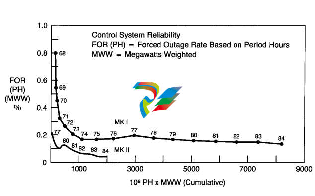
Figure 2. Control system reliability, PH is forced outage rate based on period hours; MWW is megawatt
weighted
shipped in 1987, building on gas turbine experience, including the use of many of its electronics
modules, and developing it further with Software
Implemented Fault Tolerance (SIFT). A companion single-channel system, the Mark III Plus,
aimed at the smaller industrial units, was first
shipped in 1988.
Some of the benefits from the new digital systems are flexibility and greater precision of of
the benefits from the new digital systems are flexibility and greater precision of controls because
functions are determined by software rather than
hardware, CRT operator interface, data link
interface to plant level control systems, and online repair capability for triple-redundant systems, providing further improvement in reliability.
The new SPEEDTRONIC Mark V Steam
Turbine Control System is developed from this
long evolution of electronic steam turbine controls. It is available in both triple-redundant Mark
V TMR and single-channel Mark V Simplex control systems, the only difference being the two
additional controllers in the TMR design.
STEAM TURBINE
UNIT CONTROLS
The main functions of a modern steam turbine
control system are:
• Speed and acceleration control during start-up
• Initialization of generator excitation
• Synchronization and application of load in
response to local or area generation dispatch
commands
• Pressure control of various forms: inlet,
extraction, back pressure, etc.
• Unloading and securing of the turbine
• Sequencing of the above functions under
constraint of thermal stress
• Overspeed protection during load rejection
and emergencies
• Protection against serious hazards, e.g., loss
of lube oil pressure, high exhaust temperature, high bearing vibration
• Testing of steam valves and other important
protective functions
Additional control and monitoring functions
are also required in most applications, such as:
• Monitoring and supervision of a large num
ber of pressures, temperatures, etc., to provide guidance and alarms for operators
• Start-up and monitoring of turbine-generator auxiliaries such as lube oil, hydraulic, and
steam seal systems
• Display, alarm, and recording of the above
functions and data
• Diagnosis of turbine or generator problems
• Health check and diagnostics of the electronic system itself
It is characteristic of the first group of functions
that they must be performed with high control
bandwidth, or with very high reliability, or both, to
ensure long-term reliable operation and service of
the turbine. It is for these reasons that GE has,
from the very beginning of turbine technology,
designed and provided the controls and protection for its units, starting with the MHC systems a
century ago and continuing with the new
SPEEDTRONIC Mark V control system.
For the new all-digital systems, GE has defined
the first group of functions as a “Turbine Unit
Control System." These functions, together with
the input and output devices (I/O) required, are
included in all control systems which are an integral part of steam turbines supplied by GE.
A characteristic of the unit control system is
that all essential turbine control and protection
functions are included to allow a unit to operate
safely even if other supporting systems should fail.
Another characteristic is that the “control point”
interface (i.e., the interface between the turbine
and the control system) remains in GE’s scope,
while interface to plant controls can be made at
“data point” level, which does not include critical
and rapidly varying commands and feedback signals, and therefore, is a more suitable point of
interface to possible non-GE controls. Yet another
characteristic of unit control functions is that they
must be performed either continuously or very
frequently to provide satisfactory control. Data
sampling and processing of control algorithms up
to ten times per second are used for many unit
control functions.
The second group of functions can be performed less frequently (i.e., every few seconds or
more), and turbine operation may be continued,
in most cases, during short-term interruptions in
the monitoring functions as long as the “unit control” is performing correctly.
The second group of functions includes most
of what used to be called “TSI,” for Turbine
Supervisory Instrumentation, which we now prefer to call TGM, for Turbine Generator Monitoring. The TGM functions can be included in the
Mark V systems, or they may be integrated into
the plant control system. For small- and mediumsized units, the TGM functions can be incorporated without significant extra hardware, and for
large units, additional cabinets are needed. These
cabinets can be mounted either at the turbine
and generator or in an equipment room, and they
can interface with a common Mark V operator
interface.
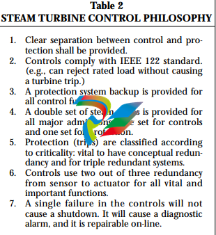
The philosophy applied to steam turbine control systems has developed over time, and it is
summarized in Table 2.
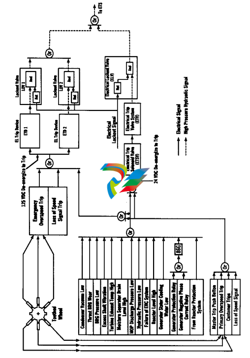
A block diagram of the protective system of the
Mark V is shown in Figure 3. The left-hand side
shows the various trip inputs entering through
redundant paths. At the extreme right is the output to the emergency trip system (ETS), a
hydraulic pressure signal, which will cause rapid
closure of all steam admission valves when depressurized. The critical inputs to the ETS can be tested on-line, one at a time, with the help of the lockout valves located immediately to the left of the
final output to the ETS. This diagram shows the
standard offering with an all-electronic overspeed
trip. Optionally, a system with a mechanical overspeed governor can be supplied.
SPEEDTRONIC MARK V
CONTROL CONFIGURATION
Figure 5 shows the configuration for the
SPEEDTRONIC Mark V triple modular redundant (TMR) control system for a medium to large
steam turbine with redundant operator interfaces.
The core of this system is the three identical controllers called <R>, <S>, and <T>. All critical control algorithms, protective functions, and sequencing are performed by these processors. In so
doing, they also acquire the data needed and generate outputs to the turbine. Protective outputs
are routed through the <P> module consisting of
triple redundant processors <X>, <Y>, and <Z>,
which also provide independent protection for
certain critical functions such as overspeed.
The three control processors, <R>, <S>, and
<T>, acquire data from the triple-redundant sensors as well as from dual or single sensors. A
generic complement of sensors is described in
Table 3. The actual number of sensors will
depend on turbine type. All critical sensors for
continuous controls, as well as protection, are
triple-redundant. Other sensors are dual or single
devices fanned out to all three control processors.
The extremely high reliability achieved by TMR
control systems is due in considerable measure to
the use of triple sensors for all critical parameters,
as it was first demonstrated with the triple-redundant protection system of the EHC Mark II.
MARK V ELECTRONICS
All of the microprocessor-based controls have a
modular design for ease of maintenance. Each
module or controller contains up to five cards,
including a power supply. Multiple processors
reside in each controller which distribute the processing for maximum performance. Individual
processors are dedicated to specific I/O assignments, application software, communications, etc.,
and the processing is performed in a real-time,
multi-tasking operating system. Communication
between the controller’s five cards is accomplished
with ribbon cables and gas-tight connectors. This
eliminates the traditional computer backplane.
Communication between individual controllers is
performed on high-speed Arcnet links.
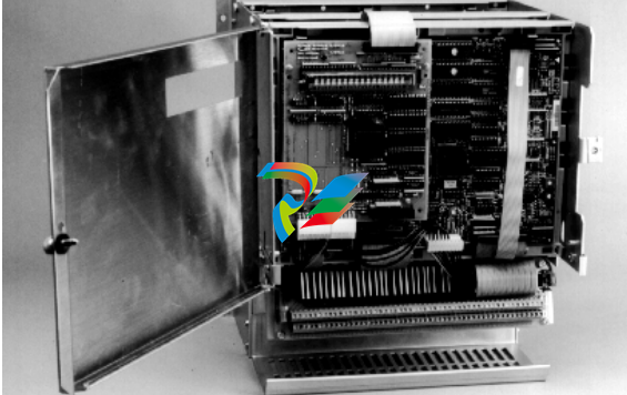
Figure 4 shows the standard microprocessor
module.
PRIMARY CONTROLLERS
<R><S><T>
The three controllers <R>, <S>, and <T>, shown
in Figure 5, are physically separate and independent modules that contain all control and protection hardware and software. A failure in any of the
three controllers is automatically diagnosed to the
card level and displayed as an alarm message.
Maintenance personnel can power down the
appropriate controller and replace the defective
card while the turbine is on-line. Redundant sensors are used in control and trip protection systems
to provide a “total system” fault-tolerant design. As
a result, diagnostics are able to distinguish between
redundant sensor failures and electronics failures.
Three basic forms of voting are used in the control. Figure 6 shows how the first form of voting,
the software implemented fault tolerance (SIFT),
works. At the beginning of each computing time
frame, each controller independently reads its sensors and exchanges this data with the data from
the other two controllers. The median value of
each analog input is calculated in each controller
and then used as the resultant control parameter
for that controller. Diagnostic algorithms monitor
a predefined deadband for each analog input to
each controller, and if one of the analog inputs
deviates from this deadband, a diagnostic alarm is
initiated to advise maintenance personnel.
Contact inputs are voted in a similar manner.
Each contact input connects to a single terminal
point and is parallel wired to three contact input
cards in the voted contact input module. Each
card optically isolates the 125 V dc input, and then
a dedicated 80196 processor in each card time
stamps the input to within 1 ms resolution. These
signals are then transmitted to the <R>, <S>, and
<T> controllers for voting and execution of the
application software. This technique eliminates
any single point failure in the software voting system. Redundant contact inputs for certain functions such as low lube oil pressure are connected
to three separate terminal points and then individually voted. With this SIFT technique, multiple
failures of contact or analog inputs can be accepted by the control system without causing an erroneous analog or trip command from any of the
three controllers as long as the failures are not
from the same circuit.
8
F
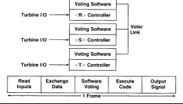
Figure 6. Software implemented fault tolerance
(SIFT)
A second form of voting is hardware voting of
analog outputs. As illustrated in Figure 7, three
coil servo valves on the steam valve actuators are
separately driven from each controller, and the
position feedback is provided by three LVDRs.
The normal position of each steam valve is the
average of the three commands from <R>, <S>,
and <T>, respectively. The resultant averaging circuit has sufficient gain to override a gross failure
of any controller, such as a controller output
being driven to saturation. Diagnostics monitor
the servo coil currents and the D/A converters in
addition to the LVDRs.
The third form of voting for the trip solenoids
is discussed under OVERSPEED.
OVERSPEED
The <P> protective controller contains three
independent cards <X>, <Y>, and <Z> with their
own processors and power supplies. This separate
set of triple-redundant electronics with its associated three separate speed pickups replaces the
mechanical overspeed governor. <R>, <S>, and
<T> use the first three pickups for speed control
and the primary overspeed protection, while <X>,
<Y>, and <Z> monitor the second set of three
pickups for emergency overspeed protection
(Figure 3).
In addition, the <X>, <Y>, and <Z> cards contain separate relay drivers and magnetic relays that
perform a final contact vote prior to driving the
turbine trip solenoids. Diagnostics monitor the
status of the output ports, relay drivers, and relays
to initiate maintenance alarms if a failure occurs.
Standard on-line and off-line primary and emergency overspeed trip tests are built in to facilitate
testing all hardware and software. Figure 8 illustrates hardware logic voting of an output from
each of three controllers.
SYNCHRONIZING
Automatic synchronization is performed by the
<X>, <Y>, and <Z> cards in conjunction with the
<R>, <S>, and <T> controllers. The controllers
match speed and voltage and issue a command to
close the breaker based on a predefined breaker
closure time. Diagnostics monitor the actual breaker closure time and self-correct each command.
Redundant sets of primary and backup phase-slip
windows eliminate the need for the traditional GXS
synchronizing check relay in the generator control
cabinet. Another feature is the ability to synchronize manually via the Mark V operator interface
instead of using the traditional synchroscope on
the generator protective cabinet. Operators can
choose one additional mode of operation by selecting the monitor mode, which automatically matches speed and voltage, but waits for the operator to
review all pertinent data on the CRT display before
issuing a breaker close command.
POWER LOAD
UNBALANCE – PLU
Large steam turbine applications use another
module similar to <P> which is designated <PLU>
for power load unbalance. This provides power
load unbalance protection and interface to the
fast closing feature on control and intercept valves
via three independent cards <U>, <V>, and <W>.
COMMON I/O <C>
A significant amount of I/O on turbines and
generators is used only for monitoring. This nonredundant I/O is monitored by the <C> module.
For example, thermocouples can be used for control and protection or just for monitoring.
Thermocouples which are used for rotor stress calculations are connected directly to the <R>, <S>,
and <T> controllers, while thermocouples that are
used for monitoring only, e.g., the thrust bearing
oil drain temperature, connect to <C>.
OPERATOR INTERFACE <I>
The interface work station <I> consists of a PC,
color monitor, cursor positioning device, keyboard, and printer. It can be used as the sole operator interface or as a local maintenance work station with all operator control and monitoring
coming from communication links with a plant
distributed control system (DCS). Figure 9 shows
the operator interface schematically.
Operators use the monitor, cursor positioning
device, and keyboard. The keyboard is not necessary. However, the keyboard is convenient for
accessing displays with dedicated function keys
and adjusting setpoints by entering a numeric
value such as 1,000 rpm rather than issuing a
manual raise/lower command. Set point and
logic commands require an initial selection, such
as the command to engage the turning gear,
which is followed by a confirming execute command. The monitor is available in various sizes
and types, and it can be used for desktop mounting, packaged as a drop-in insert for a control
room console, or mounted in a separate freestanding cabinet. The keyboard is primarily used
-
 HIRSCHMANN MSM20-M2M2M2M2SY9HH9E Ethernet media modul
 -
 HIRSCHMANN SPIDER-PL-20-05T1999999TWVHHHH Industrial Ethernet Rail Switch
 -
 Hirschmann SPIDER-PL-20-07T1M2M299TWVHHHH Industrial ETHERNET Rail Switch
 -
.png) Hirschmann (Belden) RS20-1600M2M2SDAEHC09.1.00 DIN-rail managed industrial Fast Ethernet switch
Hirschmann (Belden) RS20-1600M2M2SDAEHC09.1.00 DIN-rail managed industrial Fast Ethernet switch -
 Hirschmann (Belden) RS30-1602O6O6TDAPHC09.1.00 DIN-rail managed industrial Ethernet switch
 -
 Hirschmann (Belden) RS30-2402O6T1SDAPHH09.0.13 DIN-rail industrial Ethernet switch
 -
Hirschmann (Belden) SPIDER-PL-20-04T1S29999TY9HHHH Ethernet DIN-rail switch
-
 HIRSCHMANN RS20-1600T1T1SDAUHX Switch
 -
 HIRSCHMANN BRS42-0012OOOO-SPCZ99HHSES industrial switch
 -
 Hirschmann RS20-0800S2S2TDHPHH09.0.14 Fast Ethernet DIN rail switch.
 -
 HIRSCHMANN MM20-Z6Z6M2M2SAHH Hybrid Fast Ethernet Media Module
 -
 HIRSCHMANN MM20-Z6Z6T1T1SAHH hot-swappable hybrid Fast Ethernet Media Module
 -
 HIRSCHMANN MM20-P9P9T1T1SAHH Hybrid Fast Ethernet Media Module
 -
 HIRSCHMANN MM20-M4T1T1T1SAHH Hybrid Fast Ethernet Media Module
 -
 HIRSCHMANN MM20-M4M4T1T1SAHH Hybrid Fast Ethernet Media Module
 -
 HIRSCHMANN MM20-M2M2M2M2SZHH Ethernet media module
 -
HIRSCHMANN MM20-M2M2M2M2SAHH Ethernet media module
-
 HIRSCHMANN MM20-T1T1T1T1EBH 4-port Fast Ethernet Copper Cable Media Module
 -
HIRSCHMANN MM20-T1T1T1T1SAHH 4-port Fast Ethernet Copper Cable Media Module
-
HIRSCHMANN MM20-T1T1T1T1SAHH 4-port Fast Ethernet Copper Cable Media Module
-
 HIRSCHMANN MM20-Z6Z6EBH Hot-swappable fast Ethernet media module
 -
 HIRSCHMANN MM20-Z6Z6SAHH Ethernet media module
 -
HIRSCHMANN MM20-Z6Z6Z6Z6EBH Industrial Media Module
-
 MSM40-T1T1T1TZ9HH9E99.9.99 HIRSCHMANN Switch
 -
 HIRSCHMANN MS20-0800SAAEHC / MS20-0800SAAEHC0 8-port modular Layer 2 management Ethernet switch
 -
 Hirschmann RSPM20-4T14T1SZ9HHS9 Switch RSPM20-4T14T1SZ9HHS9
 -
 HIRSCHMANN RS20-1600M2M2SDAEHH09.1. RS20/30/40 Managed Switch configurator
 -
HIRSCHMANN RS20-1600M2M2SDAEHX09.0.00 Ethernet switch
-
 HIRSCHMANN BELDEN SPIDER-PL-20-07T1M2M299TY9HHHH / SPIDERPL2007T1M2M299TY9HHHH
 -
HIRSCHMANN MM3-1FXS2/3TX1 Switching Board Module
-
 HIRSCHMANN RSPE30-24044O7T99-ECCP999HHSE2A08.1.00 Industrial-grade fanless management-type Ethernet switch
 -
 HIRSCHMANN RS30-1602OOZZSDAEHC09.1.00 DIN-rail-mounted managed Layer 2 Ethernet switch
 -
 HIRSCHMANN MACH104-20TX-F Managed 24-port Full Gigabit 19" Switch
 -
 HIRSCHMANN Switch RS20-0800M4M4SDAE
 -
Hirschmann RS30-1602O6O6SDAEHH09.1. Management-type Ethernet switch
-
 Hirschmann RS30-1602OOZZSDAEHC09.0.10 Open rack-style Ethernet switch
 -
 HIRSCHMANN RSPE30-24044O7T99-SCCV999HHSI2SXX.X.XX High-Availability Seamless Redundancy
 -
HIRSCHMANN RSPE30-24044O7T99-SCCZ999HHSE2A DIN-rail Ethernet switch
-
HIRSCHMANN MM2-4TX1-EEC switch
-
HIRSCHMANN MSM40-T1T1T1T1TZ9HH9E99.9.99 Module
-
 HIRSCHMANN RS20 Rail Switch RS20-0400S4T1SDAEHC07.1.01
 -
 HIRSCHMANN M4-FAST8-SFP Fast Ethernet media module
 -
 HIRSCHMANN RS20-0400M2T1SDAP Managed Fast-Ethernet-Switch
 -
 HIRSCHMANN BELDEN SPIDER II 8TX/1FX EEC Industrial Ethernet Rail Switch
 -
HIRSCHMANN MM3-2FXS2/2TX1
-
 HIRSCHMANN RS2-4TX/1FX EEC Industrial Ethernet Rail Switch
 -
 RS30-0802O6O6SDAEHC09.0.10 HIRSCHMANN Switch
 -
 HIRSCHMANN m4-8TP-RJ45 Ethernet Media Module
 -
 HIRSCHMANN MSP30-24040SCZ9URHHE3A switch
 -
 Hirschmann rack MS30-1602SAAPHC
 -
 HIRSCHMANN RS2-FX/FX Industrial Switch Module
 -
Rs1txfx - Hirschmann - Rs1-Tx/Fx Rail Switch
-
RS20-0800S2S2SDAEHC09.1.00 HIRSCHMANN Commutator
-
 Hirschmann EAGLE20 TX/TX Industrial Security Router
 -
 Hirschmann SPIDER-SL-20-04T1S29999SY9HHHH Industrial Switch
 -
 HIRSCHMANN MAR1040-4C4C4C4C9999SMMHRHHXX.X. Gigabit Ethernet Switch configurator
 -
 Hirschmann MAR1040 Industrial Switch
 -
 HIRSCHMANN BELDEN RS30-1602O6O6SDAE
 -
Hirschmann RS20-1600M2M2SDAUHC Ethernet DIN rail switch
-
 HIRSCHMANN OCTOPUS 24M industrial switch
 -
 HIRSCHMANN RS20-1600T1T1SDAE Management-type Ethernet switch
 -
 HIRSCHMANN RS20-1600T1T1SDAUHH industrial switch
 -
HIRSCHMANN RS20-0800M2M2SDAPHC09.0.04 switch
-
 Hirschmann MR 8-03 24V DC Industrial Modular Bridge/Router
 -
 HIRSCHMANN RS20-0400M2T1SDAPHC08.0.01 Managed Switch
 -
 MACH1130 Hirschmann Industrial Switch
 -
 HIRSCHMANN 943824-002 SPIDER 5TX Industrial Ethernet Switch
 -
 HIRSCHMANN RS30-0802O6O6SDAEHC09.1.00 Managed Industrial Switch
 -
 HIRSCHMANN RS20-0400M2M2TDAEHC04.0.01 Industrial Switch
 -
 HIRSCHMANN BRS20-0600Z6Z6-STCZ99HHSES Industrial Switch
 -
 HIRSCHMANN MACH104-20TX-FR-L3P Industrial Ethernet Switch
 -
 HIRSCHMANN RS40-0009CCCCEDBPHH06.0.01 Industrial Switch
 -
 HIRSCHMANN RS2-3TX/2FX EEC Industrial Ethernet Switch
 -
 Hirschmann MACH 1020/1030 Fast/Gigabit Rack Mount Switches
 -
HIRSCHMANN RS20-0800M2M2SDAPHC09.0.14 Industrial Switch
-
 HIRSCHMANN RS20-1600T1T1SDAEHC09.0.04 Industrial Switch
 -
 HIRSCHMANN RSB20-0800T1T1EAABHH Industrial Switch
 -
 HIRSCHMANN MACH4002-48+4G-L3E Industrial Backbone Switch
 -
 HIRSCHMANN RS20-0400S2T1SDAE Industrial Managed Switch
 -
HIRSCHMANN RS20-0800S2T1SDAUHC Industrial Switch
-
 HIRSCHMANN RS20-2400S4S4SDAEHC09.0.14 industrial switch
 -
 HIRSCHMANN OS20-001200T5T5T5- TBBZ999HHNE3S 08.1.00 industrial switch
 -
HIRSCHMANN OS20-001200T5T5T5- TBBZ999HHNE3S 08.1.00 industrial switch
-
 HIRSCHMANN RS40-0009CCCCSDAEHH09.0.14 switch
 -
 Hirschmann RS20-1600T1T1SDAUHC Management-type Ethernet Switch
 -
 Hirschmann M1-8SFP Switche
 -
Hirschmann Industrial Ethernet Ruggedized Switch MACH1000 Family
-
 Basler Electric, Solid State Protective Relay, BE1-60
 -
BASLER ELECTRIC SR4A-2B15B3A Static Voltage Regulator
-
.png) BASLER ELECTRIC EXCITER DIODE MONITOR EDM-200
BASLER ELECTRIC EXCITER DIODE MONITOR EDM-200 -
.png) BASLER ELECTRIC DECS125-15-B2C5 DIGITAL EXCITATION CONTROL SYSTEM V 2.0.9
BASLER ELECTRIC DECS125-15-B2C5 DIGITAL EXCITATION CONTROL SYSTEM V 2.0.9 -
 BASLER ELECTRIC BE1-851 OVERCURRENT PROTECTION RELAY MECHANISM
 -
 Basler Electric BE1-51A / BE151A
 -
 Basler Electric BE1-40Q Loss of Excitation Relay
 -
 Basler Electric BE1-87G Variable Percentage Differential Relay
 -
 Basler Electric BE1-11 Protection System I5A3M2P2N0EA00
 -
 BASLER ELECTRIC DECS-200-1C Digital Excitation Control System
 -
 Basler Electric / Kohler BE1-11g Generator Protection Relay G5A3M2J2N0E000
 -
BASLER ELECTRIC DECS125-15 DIGITAL EXCITATION CONTROL SYSTEM
-
 BASLER ELECTRIC BE1-951 OverCurrent Protecton System
 -
Basler Electric DECS-200-1L Digital Excitation Control System
-
 Basler Electric DGC-2020HD-5NS1DNSBA Digital Genset Controller -
 -
 BASLER ELECTRIC BE1-81T1EE1WA0N1F / BE181T1EE1WA0N1F
 -
 BASLER ELECTRIC BE1-25M1EA6PN5R1F / BE125M1EA6PN5R1F
 -
 BASLER ELECTRIC DECS-250-LN1SN1N DIGITAL EXCITATION CONTROL SYSTEM
 -
Basler Electric DECS-250-CN2CN 1N Digital Excitation Control System Unit
-
 BASLER ELECTRIC DECS-300-C0N0 DIGITAL EXCITATION CONTROL SYSTEM
 -
 BASLER ELECTRIC BE1-87T-A1E-A1J-D0S1F / BE187TA1EA1JD0S1F
 -
BASLER ELECTRIC BE1-11-G6D1M0J2P0E000 Protection System
-
 BASLER ELECTRIC BE1-GPS100-E4N1H1N GENERATOR PROTECTION SYSTEM
 -
 Jaquet Relay card (Auxiliary module) FTV 3090 377Z-03985
 -
 Jaquet Trip Chain Control card FTBU 3034 377Z-05030
 -
 Jaquet with input card -E04 FTFU 3024 -E04 377Z-05855
 -
 Jaquet with input card -E03 FTFU 3024- E03 377Z-03983
 -
 Jaquet FTFU 3024- E02 377Z-03982 with input card -E02
 -
 Jaquet FTFU 3024-E01 377Z-03981 with input card -E01
 -
 Hirschmann RS20-2400T1T1SDAE Industrial Managed Ethernet Switch
 -
 Hirschmann BELDEN EAGLE30-04022O6TT999SCCV9HSE3F
 -
 Hirschmann MM3-2FXS2/2TX MICE Media Module
 -
 Hirschmann RS20-1600M2M2SDAPHC08.0.05 Industrial Managed Switch
 -
 Hirschmann OZD Profi 12M G12-1300 PRO Fieldbus Repeater
 -
Hirschmann SPIDER 4TX/1FX-ST EEC Industrial Ethernet Switch
-
 Hirschmann MM2-2FXM3/2TX1 MICE Media Module
 -
 Hirschmann RS20-2400M2M2SDAPHC09.0.14 Industrial Switch
 -
 Hirschmann RS20-0400M2M2SDAEHC07.1.05 OpenRail Switch
 -
 Hirschmann OZD Profi 12M G12-EEC Fieldbus Repeater
 -
HIRSCHMANN MDA422-1/2-3.5c-23/46 sensor
-
Hirschmann RS30-2402T1T1SDAUHC Managed Industrial Switch


