
GEBlocking and Test System Instruction Manual
Introduction
The GE Multilin 515 Blocking and Test Module has the following features:
• 14 Pole switchbank
• CT inputs short when current switches are opened
• Current injection for each phase
• Ground terminal
• Ability to visually isolate (open) trip relay output circuits
• Cover provided
• Suitable for utility and industrial use
• 515 test plugs available
Description
The 515 Blocking and Test Module provides an effective means of trip blocking, relay isolation and testing of GE Multilin relays. By opening the
switches and inserting test plugs, phase and residual currents from the primary CTs can be monitored. Currents can be injected into the relay from
a secondary injection test set during commissioning.
Prior to testing, the trip and auxiliary circuits must first be opened to prevent nuisance tripping; CTs can then be shorted. Conversely, when the test
is complete and the relay put back into operation, the CT switches should be closed first to ensure normal operation of the relay, prior to closing
the trip and auxiliary circuits.
Installation
Shorting switches are provided for connection of 3 phase CTs (current transformers) and a separate core balance ground fault CT or 3 phase CTs
connected for residual ground fault sensing.
When each CT switch is opened, the CT is shorted. It is essential that the CT is connected to the shorted side of the switch as shown in the following
figure, otherwise dangerously high voltages would be present from the open circuited CTs.
When the switches are open, test plugs can be inserted to either inject signals into the relay wired to the switches or monitor signals such as CT
current from the switchgear.
Figure 1: Typical wiring for connecting a 515 to a protective relay Figure 2: Typical Wiring for Zero-Sequence Ground Fault
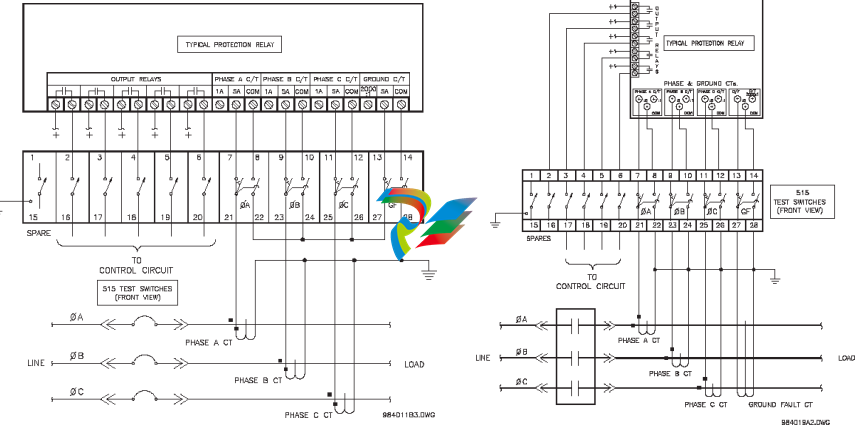
The 515 Blocking and Test Module consists of a metal chassis attached to the 515 test switches that slides into the panel. A single cutout in the panel, as per the dimensions shown in Figure 3, is required to mount the 515 test switches.
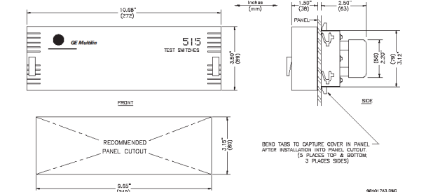
Slide the metal chassis attached to the 515 test switches into the cutout from the front of the panel. While firmly applying pressure from the front of the 515
module to ensure the chassis fits snugly, bend out the retaining tabs as shown in Figure 3. Usually the retaining tabs will be sufficient to hold the 515
module securely in place. If additional fastening is desired bend out the clamping screw tabs at both ends of the chassis at right angles. Insert the #8
screws provided in the accessory pouch into the tapped holes with the vibration proof nut between the tab and the panel. Tighten each screw until the end
of the screw butts firmly against the front panel. Ensure the nut is installed tightly against the bent tab. Nylon inserts in these nuts prevent them from
vibrating loose. The 515 test switch module should now be securely mounted to the panel with no movement ready for rear terminal wiring. When
completed, place the front cover over the mounted 515 test module and turn the fasteners at both ends ¼ turn to lock it in place, as shown in Figure 3.
As a safety precaution, a ground screw located on the bottom-right of the rear side of the module is available to be connected to panel chassis ground.
Operation
To put the 515 Blocking & Test Module into operation, additional parts have been provided:
• 1 package containing at least 28 terminal nuts
• 14 white tags for identification of each of the switches
The 515 provides a means of trip blocking, relay isolation, and testing of GE Multilin relays. The 515 accomplishes this with a total of 14 switches. There are 6
single pole throw switches for use with the output relays, and 4 groups of 2 switches each for use with the current transformers as illustrated in Figure 1:
Typical Wiring.
Isolation or opening of the relay’s output circuits is accomplished with the six switches at terminals 1 through 6 and 15 through 20.
These switches can be used to simply open the protection relay's output contacts and thus provide a means of blocking trips. The
4 remaining groups of 2 switches at terminals 7 through 14 and 21 through 28 are used for shorting of the CT inputs, injection of
test current, and measuring of CT current. The four groups correspond to Phase 1 Current, Phase 2 Current, Phase 3 Current, and
Ground Current.
Each group is made up of two switches. The first switch for the Phase 1 group is at terminal 7 and 21 and is configured as shown
on the right:
Note that terminals 7 and 21 are shorted together regardless of whether the switch is
open or closed. The second switch for the Phase 1 group is at terminals 8 and 22. It is
configured as shown on the right:
Note that this switch operates as make before break. When this switch is closed
terminals 8 and 22 are shorted together. When this switch is open, terminals 8 and 22 open and 22 shorts with 7 and 21. This in turn shorts the
Phase 1 CT. It is essential that the CT is connected to the shorted side of the switch as shown on the right.
-
 AEROTECH SM Series High-Performance Stepper Motors
 -
 AEROTECH BLMSC Series Linear Motors
 -
 AEROTECH Custom Linear Motors
 -
 AEROTECH BMS Series Brushless, Slotless Rotary Motors
 -
 AEROTECH BM Series Brushless Rotary Motors
 -
 AEROTECH BLMX Series Linear Motors
 -
 AEROTECH BLMH Series Linear Motors
 -
 AEROTECH BLM Series Linear Motors
 -
 AEROTECH BLMC Series Linear Motors
 -
 AEROTECH BLMUC-143 Linear motor forcer with thermistor
 -
AEROTECH BLMUC-111 Linear motor forcer with thermistor
-
AEROTECH BLMUC-95 Linear motor forcer with thermistor
-
AEROTECH BLMUC-79 Linear motor forcer with thermistor
-
AEROTECH BLMUC Series Linear Motors
-
 AEROTECH Automation1 FLEX Distributed Amplifier Multi-Axis Servo Control System
 -
 AEROTECH Automation1 HXA4 6-Axis Hexapod Servo Drive
 -
 AEROTECH Automation1 iHXA4 6-Axis Hexapod Servo Drive with Motion Controller
 -
 AEROTECH Modular System Control Console
 -
 AEROTECH TV Series Transformers
 -
 AEROTECH TM Series Transformers
 -
 AEROTECH UFM Noise Filter Module
 -
 AEROTECH MFM Motor Filter Module
 -
 AEROTECH MPG Handwheel Pendant
 -
 AEROTECH Automation1 Multi-Axis Joystick
 -
 AEROTECH ETM Enhanced Throughput Module
 -
 AEROTECH Automation1 XL4s High-Speed, Single-Phase Linear Servo Drive
 -
 AEROTECH Automation1 XL2e Enhanced, Compact Linear Servo Drive
 -
 Automation1 iXL2e Enhanced, Compact Linear Servo Drive with Motion Controller
 -
 AEROTECH Automation1 XL5e Enhanced, Linear Servo Drive
 -
 AEROTECH Automation1 iXL5e Enhanced Linear Servo Drive with Motion Controller
 -
 AEROTECH Automation1 GI4 Laser Scan Head Controller
 -
 AEROTECH Automation1 SI4 Stepper Interface
 -
AEROTECH Automation1 XI4 Servo Interface
-
 AEROTECH AEROTECH Automation1 iXI4 Servo Interface with Motion Controller
 -
 AEROTECH Automation1 XC6e Enhanced, High-Power PWM Servo Drive
 -
 AEROTECH Automation1 iXC6e Enhanced, High-Power PWM Servo Drive with Motion Controller
 -
 AEROTECH Automation1 XC2 Compact PWM Servo Drive
 -
 AEROTECH Automation1 XC4 PWM Servo Drive
 -
 AEROTECH Automation1 GL4 Galvo Laser Scan Head Linear Drive
 -
 AEROTECH Automation1 XC2e Enhanced, Compact Servo Drive with PWM+
 -
 AEROTECH Automation1 XC4e Enhanced, PWM Servo Drive
 -
 AEROTECH Automation1 XR3 Multi-Axis Servo Drive Rack
 -
 AEROTECH Automation1 iXR3 Multi-Axis Servo Drive Rack with Motion Controller
 -
 AEROTECH Automation1 iXC2 Compact PWM Servo Drive with Motion Controller
 -
 AEROTECH Automation1 iXC2e Enhanced, Compact PWM+ Servo Drive with Motion Controller
 -
 AEROTECH Automation1 iXC4 PWM Servo Drive with Motion Controller
 -
 AEROTECH Automation1 iXC4e Enhanced, PWM Servo Drive with Motion Controller
 -
 AEROTECH Automation1 iPC Industrial PC with Motion Controller
 -
 AEROTECH EPICS & TANGO Drivers for Distributed Control Systems
 -
 AEROTECH .NET, C, Python & LabVIEW APIs Custom Application Develotpmen
 -
 AEROTECH Automation1 Industrial Ethernet Support
 -
 AEROTECH Automation1 iSMC Intelligent, Software-Based Motion Controller
 -
 AEROTECH Automation1 iXA4 1- 2- or 4-Axis PWM Servo Drive with Motion Controller
 -
 AEROTECH Automation1 XA4 1- 2- or 4-Axis PWM Servo Drive
 -
 CTI 2500-ADP2-DISC Discrete Wiring Adapter for Series 500
 -
 CTI 2500-ADP1 Analog Wiring Adapter for Series 500
 -
 CTI 2500C-RADP-RS485 Remote Base Controller Adapter for Series 500
 -
 CTI 2500C-RADP-RBC Profibus RBC Adapter for Series 500
 -
 CTI 2500C-PADP-120V 120VAC 50W Power Supply for Series 500
 -
 CTI 2500-RADP RBC Adapter for Series 500
 -
 CTI 2500-R4500 520/530/DBC Adapter for Series 500 - MATURE
 -
 CTI 2500-PADP Power Supply Adapter for Series 500
 -
 CTI 2500-IADP I/O Adapter for Series 500
 -
 CTI 2500-VP15A-N4-W7 15" Flat-Panel PC with Windows® 7 Embedded
 -
 CTI 2500S-27-1750 Slice I/O, Ethernet, RS232/485. 900MHz, 2DIO / 4UAI / 2AI
 -
 CTI 2500S-26-1750 Slice I/O, Ethernet, RS232/485. 900MHz, 8DIO / 2UAI
 -
 CTI 2500S-23-1750 Slice I/O, Ethernet, RS232/485. 900MHz, 4DI / 4DO / 2UAI / 2AO
 -
 CTI 2500S-27-1550 Slice I/O, RS232/485. 2DIO / 4UAI / 2AI
 -
 CTI 2500S-26-1550 Slice I/O, RS232/485. 8DIO / 2UAI
 -
 CTI 2500S-23-1550 Slice I/O, RS232/485. 4DI / 4DO / 2UAI / 2AO
 -
 CTI 2500S-27-1050 Slice I/O, Ethernet, 2DIO / 4UAI / 2AI
 -
 CTI 2500S-26-1050 Slice I/O, Ethernet, 8DIO / 2UAI
 -
 CTI 2500S-23-1050 Slice I/O, Ethernet, 4DI / 4DO / 2UAI / 2AO
 -
 CTI 2500C-32F-CJC 32-Pin Field Wiring Connector with Cold Junction Compensation
 -
 CTI 2500C-32F 32-Pin Field Wiring Connector
 -
 CTI 2500C-8-TC Eight Thermocouple Inputs
 -
 CTI 2500C-8-RTD Eight RTD Inputs
 -
 CTI 2500C-8-RL-FC 8 Form-C Relay Outputs
 -
 CTI 2500C-8-IDO-24V 8 Isolated 24VDC Outputs
 -
 CTI 2500C-8-IDO-120V 8 Isolated 120VAC Outputs
 -
 CTI 2500C-16-DO-24V Sixteen 24VDC Digital Outputs
 -
 CTI 2500C-16-DO-120V Sixteen 120VAC Digital Outputs
 -
.png) CTI 500C-16-IDI-24V Sixteen Isolated 24V AC/DC Digital Inputs
CTI 500C-16-IDI-24V Sixteen Isolated 24V AC/DC Digital Inputs -
 CTI 2500C-16-IDI-120V Sixteen Isolated 120V AC/DC Digital Inputs
 -
 CTI 2500C-16-DIDO-SIM Sixteen Digital Input and Output SImulator
 -
 CTI 2500C-16-DI-24V Sixteen 24V AC/DC Digital Inputs
 -
 CTI 2500C-16-DI-120V Sixteen 120V AC/DC Digital Inputs
 -
 CTI 2500C-RBC-RS485 RS485 Remote Base Controller
 -
 CTI 2500C-RBC-PRF Profibus Remote Base Controller
 -
 CTI 2500C-PS-24V-35 35-Watt DC Power Supply
 -
 CTI 2500C-PS-120V-35 35-Watt AC Power Supply
 -
 CTI 2500C-R8 Eight-Slot Base
 -
 CTI 2500C-R4 Four-Slot Base
 -
 CTI 2500C-R16 Sixteen-Slot Base
 -
 CTI 2500C-2572-B Fast Ethernet TCP/IP Adapter
 -
 CTI 2500C-J750 Compact Janus PAC with 3MB Project Memory
 -
 CTI 2500C-C300 CPU with 512K User Memory
 -
 CTI 2500C-C200 CPU with 256K User Memory
 -
 CTI 2500C-C100 CPU with 128K User Memory
 -
 CTI 2500C-8-AO 8 Analog Outputs
 -
 CTI 2500C-8-AI 8 Analog Inputs
 -
 CTI 2559-FCAL Precision Calibration Connector
 -
 CTI 2559-FPC 40-Position Screw-Terminal Connector
 -
 CTI 2500-RFC PLC to RF Modem Cable
 -
 CTI 2500-40F 40-Position Standard Screw-Terminal Connector
 -
 CTI 2505 Vibration Sensor Interface Module
 -
 CTI 2554-A 4-Channel Isolated High Speed Counter Module
 -
 CTI 2553-A 2-Channel Mag Meter Input Module
 -
 CTI 2502 2-Channel High Speed Counter Input Module
 -
 CTI 2559-TC 8-Channel Thermocouple Input Module
 -
 CTI 2556-A 16-Channel Isolated Thermocouple Input Module
 -
 CTI 2556 16-Channel Isolated Thermocouple Input Module
 -
 CTI 2551-A 8-Channel Isolated Thermocouple Input Module
 -
 CTI 2559-RTD 8-Channel RTD Input Module
 -
 CTI 2557-A 16-Channel RTD Input Module
 -
 CTI 2557 16-Channel RTD Input Module
 -
 CTI 2552-A 8-Channel Isolated RTD Input Module
 -
 CTI 2534 8-Point Form-C Relay Output Module
 -
 CTI 2532 16-Point Form-A Relay Output Module
 -
 CTI 2531 32-Point Form-A Relay Output Module
 -
 CTI 2530 8-Point Form-C Relay Output Module
 -
 CTI 2562 8-Channel Analog Output Module
 -
 CTI 2560-A 8-Channel Isolated Analog Output Module
 -
 CTI 2501 8in/4out Analog Module
 -
 CTI 2558 8-Channel Analog Input Module
 -
 CTI 2555-A 16-Channel Analog Input Module
 -
 CTI 2550-A 8-Channel Isolated Analog Input Module
 -
 CTI 2599 8/16/32-Point AC Output Module


