
GEMVME51005E Single Board Computer Installation and Use
Safety Summary
The following general safety precautions must be observed during all phases of operation, service, and repair of
this equipment. Failure to comply with these precauti ons or wi th specific warnings elsewhere in t his manual
could result in personal injury or damage to the equipment.
The safety precautions listed below represent warnings of certain dangers of which Emerson is aware. You, as the
user of th e product, sho uld follow these w arnings and al l o ther saf ety precauti ons necessary f or the sa fe
operation of the equipmentin your operating environment.
Ground the Instrument.
To minimize shockhazard, the equipment chassis and enclosure must be connected to an electrical ground. If the
equipment i s su pplied wi th a three-conductor A C p ower cable , the powe r cable m ust be plu gged in to an
approved three-contact electrical outl et, w ith t he grounding wire (g reen/yellow) reliably c onnected t o an
electrical ground (safety ground) at the power outlet. The power jack and mating plug of the power cable meet
International Electrotechnical Commission (IEC) safety standards and local electrical regulatory codes.
Do Not Operate in an Explosive Atmosphere.
Do not operate the equipment in any explosive atmosphere such as in the presence of flammable gases or fumes.
Operation of any electrical equipment in such an environment could result in an explosion and cause injury or
damage.
Keep Away From Live Circuits Inside the Equipment.
Operating personnel must not remove equipment covers. Only Factory Authorized Service Personnel or o ther
qualified service personnel may remove equipment covers for internal subassembly or component replacement
or any internal adjustment. Se rvice pe rsonnel should not replace components with power cable c onnected.
Under certain conditions, dangerous voltages may exist even with the power cable removed. To avoid injuries,
such personnel should always disconnect power and discharge circuits before touching components.
Use Caution When Exposing or Handling a CRT.
Breakage o f a C athode-Ray Tube (CR T) cau ses a h igh-velocity s cattering o f gl ass fra gments (i mplosion). To
prevent CRT implosion, do not handle the CRT and avoid rough handling or jarring of the equipment. Handling of
a CRT should be done only by qualified service personnel using approved safety mask and gloves.
Do Not Substitute Parts or Modify Equipment.
Do not install substitute parts or perform any unauthorized modification of the equipment. Contact your local
Emerson representative for service and repair to ensure that all safety features are maintained.
Observe Warnings in Manual.
Warnings, suc h a s the e xample be low, precede po tentially d angerous proc edures thro ughout this m anual.
Instructions contained in the warnings must be followed. You should also employ all other safety precautions
which you deem necessary for the operation of the equipment in your operating environment.
Warning
To prevent serious injury or death from dangerous voltages, use extreme
caution when handling, testing, and adjusting this equipment and its
components.
Flammability
All Emerson PWBs (printed wiring boards) are manufactured with a flammability rating of 94V-0 by
UL-recognized manufacturers.
EMI Caution
!
Caution
This equipment generates, uses and can radiate electromagnetic energy. It may cause or be
susceptible to electromagnetic interference (EMI) if not installed and used with adequate EMI
protection.
Lithium Battery Caution
This product contains a lithium battery to power the clock and calendar circuitry. Only properly
trained service personnel should remove or install lithium batteries.
!
Caution
Danger of explosion if battery is replaced incorrectly. Replace battery only with the same or
equivalent type recommended by the equipment manufacturer. Dispose of used batteries
according to the manufacturer’s instructions.
Attention
!
Il y a danger d’explosion s’il y a remplacement incorrect de la batterie. Remplacer uniquement
avec une batterie du même type ou d’un type équivalent recommandé par le constructeur.
Mettre au rebut les batteries usagées conformément aux instructions du fabricant.
Vorsicht
!
Explosionsgefahr bei unsachgemäßem Austausch der Batterie. Ersatz nur durch denselben oder
einen vom Hersteller empfohlenen Typ. Entsorgung gebrauchter Batterien nach Angaben des
Herstellers.
CE Notice (European Community)
!
Warning
Warning
This is a Class A product. In a domestic environment, this product may cause radio interference,
in which case the user may be required to take adequate measures.
Emerson products with the CE marking comply with the EMC Directive (89/336/EEC). Compliance
with this directive implies conformity to the following European Norms:
EN55022 “Limits and Methods of Measurement of Radio Interference Characteristics of
Information Technology Equipment”; this product tested to Equipment Class A
EN 300 386 V.1.2.1 “Electromagnetic compatibility and radio spectrum matters (ERM);
Telecommunication network equipment; Electromagnetic compatibility (EMC) requirements”
System products also fulfill EN60950 (product safety) which is essentially the requirement for the
Low Voltage Directive (73/23/EEC).
Board products are tested in a representative system to show compliance with the above
mentioned requirements. A proper installation in a CE-marked system will maintain the required
EMC/safety performance.
In accordance with European Community directives, a “Declaration of Conformity” has been made
and is on file within the European Union. The “Declaration of Conformity” is available on request.
Please contact your sales representative.
The product has been designed to meet the directive on the restriction of the use of certain
hazardous substances in electrical and electronic equipment (RoHS) Directive 2002/95/EC.
The MVME51005E Single Board Computer Installation and Use provides the information you will need
to install and configure your MVME51005E Single Board Computer. It provides specific preparation
and installation information and data applicable to the board. The MVME51005E will hereafter be
referred to as the MVME5100.
The MVME5100 is a high-performance VME single board computer featuring the PowerPlus II
architecture with a choice of processors–either the MPC7410 with AltiVec™ technology for
algorithmic intensive computations or the low-power MPC750.
As of the printing date of this manual, the MVME5100 is available in the configurations shown
below. Note: all models of the MVME5100 are available with either VME Scanbe front panel or IEEE
1101 compatible front panel handles
Model Number Description
450MHz MCP750 Commercial Models
MVME51005E-016x 450MHz MCP750, 512MB ECC SDRAM, 17MB Flash and 1MB L2
cache.
400 and 500 MHz MPC7410 Commercial Models
MVME51105E-216x 400MHz MPC7410, 512MB ECC SDRAM, 17MB Flash and 2MB
L2 cache.
MVME51105E-226x 500 MHz MPC7410, 512MB ECC SDRAM, 17MB Flash and 2MB
L2 cache
MVME712M Compatible I/O
IPMC7126E-002 Multifunction rear I/O PMC module; 8-bit SCSI, Ultra Wide SCSI,
one parallel port, three async and one sync/async serial port.
MVME712M6E Transition module connectors: One DB-25 sync/async serial port,
three DB-25 async serial ports, one AUI connector, one D-36
parallel port, and one 50-pin 8-bit SCSI; includes 3-row DIN P2
adapter module and cable.
MVME761 Compatible I/O
IPMC7616E-002 Multifunction rear I/O PMC module; 8-bit SCSI, one parallel port,
two async and two sync/async serial ports.
MVME7616E-001 Transition module: Two DB-9 async serial port connectors, two HD26 sync/async serial port connectors, one HD-36 parallel port
connector, and one RJ-45 10/100 Ethernet connector; includes 3-
row DIN P2 adapter module and cable (for 8-bit SCSI).
MVME7616E-011 Transition module: Two DB-9 async serial port connectors, two HD26 sync/async serial port connectors, one HD-36 parallel port
connector, and one RJ-45 10/100 Ethernet connector; includes 5-
row DIN P2 adapter module and cable (for 16-bit SCSI); requires
backplane with 5-row DIN connectors.
SIM232DCE5E or DTE EIA-232 DCE or DTE Serial Interface Module.
Overview of Contents
The following paragraphs briefly describe the contents of each chapter.
Chapter 1, Hardware Preparation and Installation, provides a description of the MVME5100 and its
main integratedPMC and IPMC boards. The remainder ofthe chapter includes an explanation of the
installation procedure, including preparation and jumper setting information.
Chapter 2, Operation, provides a description of the operational functions of the MVME5100
including tips on applying power, a description of the switch settings, the status indicators, I/O
connectors, and system power up information.
Chapter 3, PPCBug Firmware, provides an explanation of the debugger firmware, PPCBug, on the
MVME5100. The chapter includes an overview of the firmware, a section on how to use PPCBug, a
listing of the initialization steps, a brief explanation of thetwomain configuration commands CNFG
and ENV, and a description of the standard configuration parameters. A listing of the basic
commands are also provided.
Chapter 4, Functional Description, provides a summary of the MVME5100 features, a block diagram,
and a description of the major functional areas.
Chapter 5, RAM500 Memory Expansion Module, provides a description of the RAM500 Memory
Expansion Module, a list of features, a block diagram of the module, a table of memory size
allocations, an installation procedure, and pinouts of the module’s top and bottom side
connectors.
Chapter 6, Pin Assignments, provides a listing of all connector and header pin assignments for the
MVME5100.
provides a description of the memory maps on the
MVME5100 including tables of default processor memory maps, suggested CHRP memory maps
and Hawk PPC register values for suggested memory maps. The remainder of the chapter provides
some programming considerations.
Appendix A, Specifications, provides the standard specifications for the MVME5100, as well as some
general information on cooling.
Appendix B, Troubleshooting, provides a brief explanation of the possible resolutions for basic error
conditions.
Appendix C, Thermal Analysis, gives systems integrators the information necessary to conduct
thermal evaluations of the board in their specific system configuration.
Appendix D, Related Documentation, provides a listing of related documentation for the MVME5100,
including vendor documentation and industry related specifications.
Comments and Suggestions
We welcome and appreciate your comments on our documentation. We want to know what you
think about our manuals and how we can make them better.
Mail comments to us by filling out the following online form:
http://www.emersonnetworkpowerembeddedcomputing.com/ > Contact Us > Online Form
In “Area of Interest” select “Technical Documentation”. Be sure to include the title, part number,
and revision of the manual and tell us how you used it.
Conventions Used in This Manual
The following typographical conventions are used in this document:
bold
is used for user input that you type just as it appears; it is also used for
commands, options and arguments to commands, and names of
programs, directories and files.
italic
is used for names of variables to which you assign values. Italic is also
used for comments in screen displays and examples, and to introduce
new terms.
courier
is used for system output (for example, screen displays, reports),
examples, and system prompts.
<Enter>, <Return> or <CR>
<CR> represents the carriage return or Enter key.
represents the Control key. Execute control characters by pressing the
Ctrl key and the letter simultaneously, for example, Ctrl-d.
Terminology
A character precedes a data or address parameter to specify the numeric format, as follows (if not
specified, the format is hexadecimal):
An asterisk (*) following a signal name for signals that are level significant denotes that the signal is
true or valid when the signal is low.
An asterisk (*) following a signal name for signals that are edge significant denotes that the actions
initiated by that signal occur on high to low transition.
In this manual, assertion and negation are used to specify forcing a signal to a particular state. In
particular, assertion and assert refer to a signal that is active or true; negation and negate indicate a
signal that is inactive or false. These terms are used independently of the voltage level (high or low)
that they represent. Data and address sizes are defined as follows:
0x Specifies a hexadecimal number
% Specifies a binary number
& Specifies a decimal number
Byte 8 bits, numbered 0 through 7, with bit 0 being the least significant.
Half word 16 bits, numbered 0 through 15, with bit 0 being the least
significant.
Word 32 bits, numbered 0 through 31, with bit 0 being the least
significant.
Double word 64 bits, numbered 0 through 63, with bit 0 being the least
significant.
Introduction
This chapter provides information on hardware preparation and installation for the MVME5100
Series of Single Board Computers.
Note Unless otherwise specified, the designation “MVME5100” refers to all models of the
MVME5100-series Single Board Computers.
Getting Started
The following subsections include information helpful in preparing your equipment. It includes and
overview of the MVME5100, any equipment needed to complete the installation, and unpacking
instructions.
Overview and Equipment Requirements
The MVME5100 interfaces to a VMEbus system via its P1 and P2 connectors and contains two IEEE
1386.1 PCI Mezzanine Card (PMC) Slots. The PMC Slots are 64-bit and support both front and rear
I/O.
Additionally, the MVME5100 is user configurable by setting on-board jumpers. Two I/O modes are
possible: PMC mode or SBC mode (also called 761 or IPMC mode). The SBC mode uses the IPMC712
I/O PMC and the MVME712M Transiton Module, or the IPMC761 I/O PMC and the MVME761
Transition Module. The SBC mode is backwards compatible with the MVME761 transition card and
the P2 adapter card (excluding PMC I/O routing) used on the MVME2600/2700 product. This mode
is accomplished by configuring the on-board jumpers and by attaching an IPMC761 PMC in PMC
slot 1. Secondary Ethernet is configured to the rear.
PMC mode is backwards compatible with the MVME2300/MVME2400 and is accomplished by
simply configuring the on-board jumpers.
The following equipment list is appropriate for use in an MVME5100 system:
❏ PMCspan PCI expansion mezzanine module (mates with MVME5100)
❏ Peripheral Component Interconnect (PCI) Mezzanine Cards (PMCs) (installed on an
MVME5100 board)
❏ RAM500 memory mezzanine modules (installed on an MVME5100 board)
❏ VME system enclosure
❏ System console terminal
❏ Disk drives (and/or other I/O) and controllers
Unpacking Instructions
Avoid touching areas of integrated circuitry; static discharge can damage these
circuits.
Note If the shipping carton(s) is/are damaged upon receipt, request that the carrier's agent be
present during the unpacking and inspection of the equipment.
Use ESD
Wrist Strap
Emerson strongly recommends that you use an antistatic wrist strap and a
conductive foam pad when installing or upgrading a system.
Electronic components, such as disk drives, computer boards and memory
modules, can be extremely sensitive to electrostatic discharge (ESD). After
removing the component from its protective wrapper or from the system, place
the component on a grounded, static-free, and adequately protected working
surface. Do not slide the component over any surface. In the case of a Printed
Circuit Board (PCB), place the board with the component side facing up.
If an ESD station is not available, you can avoid damage resulting from ESD by
wearing an antistatic wrist strap (available locally) that is attached to an active
electrical ground.
Note A system chassis may not be a suitable grounding source if it is unplugged.
Preparation
This section includes subsections on hardware configuration that may need to be performed
immediately before and after board installation. It includes a brief reminder on setting bits in
control registers, setting jumpers for the appropriate configuration, and other VME data
considerations.
Hardware Configuration
To produce the desired board configuration and to ensure proper operation of the MVME5100, it
may be necessary to perform certain modifications before and after installation. The following
paragraphs discuss the preparation of the MVME5100 hardware components prior to installing
them into a chassis and connecting them.
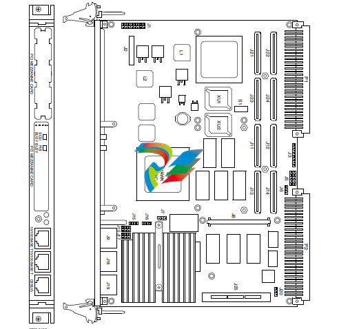
A software readable header/ switch register (S1) is available on the MVME5100. This switch is not
defined by the hardware and it is shipped in the OFF position, as are all the switches on this board.
This S1 switch is available for user-specific configuration needs via the control registers.
The MVME5100 provides software control over most of its options by setting bits in control
registers. After installing it in a system, you can modify its configuration. For additional
information on the board’s control registers, refer to the MVME5100 Single Board Computer
Programmer's Reference Guide listed in Appendix D, Related Documentation.
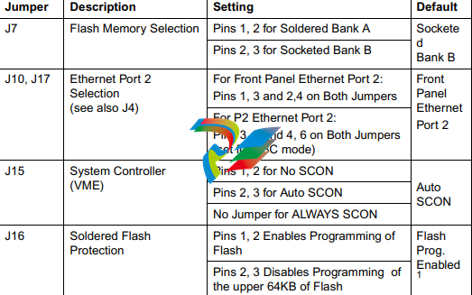
It is important to note that some options are not software-programmable. These specific options
are controlled through manual installation or removal of jumpers, and in some cases, the addition
of other interface modules on the MVME5100. The following table lists the manually configured
jumpers on the MVME5100, and their default settings.
If you are resetting the board jumpers from their default settings, it is important to verify that all
settings are reset properly. For example, the SBC mode requires setting jumpers 4, 10 and 17 for
rear Ethernet functions, but it also requires resetting jumpers J6 and J20. Neglecting to reset J6 and
J20 could damage or destroy subsequent PMCs or PrPMCs installed on the base board at power-up.
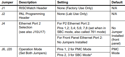
Table 1-1. Manually Configured Headers/Jumpers (continued)
Introduction
This chapter provides information on hardware preparation and installation for the MVME5100
Series of Single Board Computers.
Note Unless otherwise specified, the designation “MVME5100” refers to all models of the
MVME5100-series Single Board Computers.
Getting Started
The following subsections include information helpful in preparing your equipment. It includes and
overview of the MVME5100, any equipment needed to complete the installation, and unpacking
instructions.
Overview and Equipment Requirements
The MVME5100 interfaces to a VMEbus system via its P1 and P2 connectors and contains two IEEE
1386.1 PCI Mezzanine Card (PMC) Slots. The PMC Slots are 64-bit and support both front and rear
I/O.
Additionally, the MVME5100 is user configurable by setting on-board jumpers. Two I/O modes are
possible: PMC mode or SBC mode (also called 761 or IPMC mode). The SBC mode uses the IPMC712
I/O PMC and the MVME712M Transiton Module, or the IPMC761 I/O PMC and the MVME761
Transition Module. The SBC mode is backwards compatible with the MVME761 transition card and
the P2 adapter card (excluding PMC I/O routing) used on the MVME2600/2700 product. This mode
is accomplished by configuring the on-board jumpers and by attaching an IPMC761 PMC in PMC
slot 1. Secondary Ethernet is configured to the rear.
PMC mode is backwards compatible with the MVME2300/MVME2400 and is accomplished by
simply configuring the on-board jumpers.
The following equipment list is appropriate for use in an MVME5100 system:
❏ PMCspan PCI expansion mezzanine module (mates with MVME5100)
❏ Peripheral Component Interconnect (PCI) Mezzanine Cards (PMCs) (installed on an
MVME5100 board)
❏ RAM500 memory mezzanine modules (installed on an MVME5100 board)
❏ VME system enclosure
❏ System console terminal
❏ Disk drives (and/or other I/O) and controllers
❏ Operating system (and/or application software)
Unpacking Instructions
Avoid touching areas of integrated circuitry; static discharge can damage these
circuits.
Note If the shipping carton(s) is/are damaged upon receipt, request that the carrier's agent be
present during the unpacking and inspection of the equipment.
Use ESD
Wrist Strap
Emerson strongly recommends that you use an antistatic wrist strap and a
conductive foam pad when installing or upgrading a system.
Electronic components, such as disk drives, computer boards and memory
modules, can be extremely sensitive to electrostatic discharge (ESD). After
removing the component from its protective wrapper or from the system, place
the component on a grounded, static-free, and adequately protected working
surface. Do not slide the component over any surface. In the case of a Printed
Circuit Board (PCB), place the board with the component side facing up.
If an ESD station is not available, you can avoid damage resulting from ESD by
wearing an antistatic wrist strap (available locally) that is attached to an active
electrical ground.
Note A system chassis may not be a suitable grounding source if it is unplugged.
Preparation
This section includes subsections on hardware configuration that may need to be performed
immediately before and after board installation. It includes a brief reminder on setting bits in
control registers, setting jumpers for the appropriate configuration, and other VME data
considerations.
Hardware Configuration
To produce the desired board configuration and to ensure proper operation of the MVME5100, it
may be necessary to perform certain modifications before and after installation. The following
paragraphs discuss the preparation of the MVME5100 hardware components prior to installing
them into a chassis and connecting them.
A software readable header/ switch register (S1) is available on the MVME5100. This switch is not
defined by the hardware and it is shipped in the OFF position, as are all the switches on this board.
This S1 switch is available for user-specific configuration needs via the control registers.
The MVME5100 provides software control over most of its options by setting bits in control
registers. After installing it in a system, you can modify its configuration. For additional
information on the board’s control registers, refer to the MVME5100 Single Board Computer
Programmer's Reference Guide listed in Appendix D, Related Documentation.
It is important to note that some options are not software-programmable. These specific options
are controlled through manual installation or removal of jumpers, and in some cases, the addition
of other interface modules on the MVME5100. The following table lists the manually configured
jumpers on the MVME5100, and their default settings.
If you are resetting the board jumpers from their default settings, it is important to verify that all
settings are reset properly. For example, the SBC mode requires setting jumpers 4, 10 and 17 for
rear Ethernet functions, but it also requires resetting jumpers J6 and J20. Neglecting to reset J6 and
J20 could damage or destroy subsequent PMCs or PrPMCs installed on the base board at power-up.
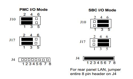
Table 1-1. Manually Configured Headers/Jumpers
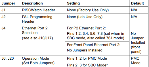
PMC/SBC (761/IPMC) Mode Selection
There are five headers associated with the selection of the PMC or SBC mode: J4, J6 J10,J17 and J20.
Three of these headers are responsible for secondary Ethernet I/O (J4, J10 and J17) to either the
front panel (PMC mode), or to the P2 connector via J4 (SBC mode). The other two headers (J6 and
J20) ensure proper routing of +/- 12V signal routing. The MVME5100 is set at the factory for front
panel I/O: PMC mode (see Table 1-1). The SBC mode should only be selected when using one of the
IPMC-7xx modules in conjunction with the corresponding MVME7xx transition module.
Installation Considerations
The MVME5100 draws power from the VMEbus backplane connectors P1 and P2. Connector P2 is
also used for the upper 16 bits of data in 32-bit transfers, and for the upper 8 address lines in
extended addressing mode. The MVME5100 will not function properly without its main board
connected to VMEbus backplane connectors P1 and P2.
Whether the MVME5100 operates as a VMEbus master or as a VMEbus slave, it is configured for 32
bits of address and 32 bits of data (A32/D32). However, it handles A16 or A24 devices in the
appropriate address ranges. D8 and/or D16 devices in the system must be handled by the
processor software.
If the MVME5100 tries to access off-board resources in a nonexistent location and if the system
does not have a global bus time-out, the MVME5100 waits indefinately for the VMEbus cycle to
complete. This will cause the system to lock up. There is only one situation in which the system
might lack this global bus time-out; that is when the MVME5100 is not the system controller and
there is no global bus time-out elsewhere in the system.
Note Software can also disable the bus timer by setting the appropriate bits in the Universe II
VMEbus interface.
Multiple MVME5100 boards may be installed in a single VME chassis; however, each must have a
unique VMEbus address. Other MPUs on the VMEbus can interrupt, disable, communicate with,
and determine the operational status of the processor(s).
Installation
This section discusses the installation of PMCs onto the MVME5100, installation of PMCspan
modules onto the MVME5100, and the installation of the MVME5100 into a VME chassis.
Note If you have ordered one or more of the optional RAM500 memory mezzanine boards for
the MVME5100, ensure that they are installed on the board prior to proceeding. If they
have not been installed by the factory, and you are installing them yourself, please refer to
Chapter 5, RAM500 Memory Expansion Module, for installation instructions. It is
recommended that the memory mezzainine modules be installed prior to installing other
board accessories, such as PMCs, IPMCs or transition modules
-
 HIRSCHMANN MSM20-M2M2M2M2SY9HH9E Ethernet media modul
 -
 HIRSCHMANN SPIDER-PL-20-05T1999999TWVHHHH Industrial Ethernet Rail Switch
 -
 Hirschmann SPIDER-PL-20-07T1M2M299TWVHHHH Industrial ETHERNET Rail Switch
 -
.png) Hirschmann (Belden) RS20-1600M2M2SDAEHC09.1.00 DIN-rail managed industrial Fast Ethernet switch
Hirschmann (Belden) RS20-1600M2M2SDAEHC09.1.00 DIN-rail managed industrial Fast Ethernet switch -
 Hirschmann (Belden) RS30-1602O6O6TDAPHC09.1.00 DIN-rail managed industrial Ethernet switch
 -
 Hirschmann (Belden) RS30-2402O6T1SDAPHH09.0.13 DIN-rail industrial Ethernet switch
 -
Hirschmann (Belden) SPIDER-PL-20-04T1S29999TY9HHHH Ethernet DIN-rail switch
-
 HIRSCHMANN RS20-1600T1T1SDAUHX Switch
 -
 HIRSCHMANN BRS42-0012OOOO-SPCZ99HHSES industrial switch
 -
 Hirschmann RS20-0800S2S2TDHPHH09.0.14 Fast Ethernet DIN rail switch.
 -
 HIRSCHMANN MM20-Z6Z6M2M2SAHH Hybrid Fast Ethernet Media Module
 -
 HIRSCHMANN MM20-Z6Z6T1T1SAHH hot-swappable hybrid Fast Ethernet Media Module
 -
 HIRSCHMANN MM20-P9P9T1T1SAHH Hybrid Fast Ethernet Media Module
 -
 HIRSCHMANN MM20-M4T1T1T1SAHH Hybrid Fast Ethernet Media Module
 -
 HIRSCHMANN MM20-M4M4T1T1SAHH Hybrid Fast Ethernet Media Module
 -
 HIRSCHMANN MM20-M2M2M2M2SZHH Ethernet media module
 -
HIRSCHMANN MM20-M2M2M2M2SAHH Ethernet media module
-
 HIRSCHMANN MM20-T1T1T1T1EBH 4-port Fast Ethernet Copper Cable Media Module
 -
HIRSCHMANN MM20-T1T1T1T1SAHH 4-port Fast Ethernet Copper Cable Media Module
-
HIRSCHMANN MM20-T1T1T1T1SAHH 4-port Fast Ethernet Copper Cable Media Module
-
 HIRSCHMANN MM20-Z6Z6EBH Hot-swappable fast Ethernet media module
 -
 HIRSCHMANN MM20-Z6Z6SAHH Ethernet media module
 -
HIRSCHMANN MM20-Z6Z6Z6Z6EBH Industrial Media Module
-
 MSM40-T1T1T1TZ9HH9E99.9.99 HIRSCHMANN Switch
 -
 HIRSCHMANN MS20-0800SAAEHC / MS20-0800SAAEHC0 8-port modular Layer 2 management Ethernet switch
 -
 Hirschmann RSPM20-4T14T1SZ9HHS9 Switch RSPM20-4T14T1SZ9HHS9
 -
 HIRSCHMANN RS20-1600M2M2SDAEHH09.1. RS20/30/40 Managed Switch configurator
 -
HIRSCHMANN RS20-1600M2M2SDAEHX09.0.00 Ethernet switch
-
 HIRSCHMANN BELDEN SPIDER-PL-20-07T1M2M299TY9HHHH / SPIDERPL2007T1M2M299TY9HHHH
 -
HIRSCHMANN MM3-1FXS2/3TX1 Switching Board Module
-
 HIRSCHMANN RSPE30-24044O7T99-ECCP999HHSE2A08.1.00 Industrial-grade fanless management-type Ethernet switch
 -
 HIRSCHMANN RS30-1602OOZZSDAEHC09.1.00 DIN-rail-mounted managed Layer 2 Ethernet switch
 -
 HIRSCHMANN MACH104-20TX-F Managed 24-port Full Gigabit 19" Switch
 -
 HIRSCHMANN Switch RS20-0800M4M4SDAE
 -
Hirschmann RS30-1602O6O6SDAEHH09.1. Management-type Ethernet switch
-
 Hirschmann RS30-1602OOZZSDAEHC09.0.10 Open rack-style Ethernet switch
 -
 HIRSCHMANN RSPE30-24044O7T99-SCCV999HHSI2SXX.X.XX High-Availability Seamless Redundancy
 -
HIRSCHMANN RSPE30-24044O7T99-SCCZ999HHSE2A DIN-rail Ethernet switch
-
HIRSCHMANN MM2-4TX1-EEC switch
-
HIRSCHMANN MSM40-T1T1T1T1TZ9HH9E99.9.99 Module
-
 HIRSCHMANN RS20 Rail Switch RS20-0400S4T1SDAEHC07.1.01
 -
 HIRSCHMANN M4-FAST8-SFP Fast Ethernet media module
 -
 HIRSCHMANN RS20-0400M2T1SDAP Managed Fast-Ethernet-Switch
 -
 HIRSCHMANN BELDEN SPIDER II 8TX/1FX EEC Industrial Ethernet Rail Switch
 -
HIRSCHMANN MM3-2FXS2/2TX1
-
 HIRSCHMANN RS2-4TX/1FX EEC Industrial Ethernet Rail Switch
 -
 RS30-0802O6O6SDAEHC09.0.10 HIRSCHMANN Switch
 -
 HIRSCHMANN m4-8TP-RJ45 Ethernet Media Module
 -
 HIRSCHMANN MSP30-24040SCZ9URHHE3A switch
 -
 Hirschmann rack MS30-1602SAAPHC
 -
 HIRSCHMANN RS2-FX/FX Industrial Switch Module
 -
Rs1txfx - Hirschmann - Rs1-Tx/Fx Rail Switch
-
RS20-0800S2S2SDAEHC09.1.00 HIRSCHMANN Commutator
-
 Hirschmann EAGLE20 TX/TX Industrial Security Router
 -
 Hirschmann SPIDER-SL-20-04T1S29999SY9HHHH Industrial Switch
 -
 HIRSCHMANN MAR1040-4C4C4C4C9999SMMHRHHXX.X. Gigabit Ethernet Switch configurator
 -
 Hirschmann MAR1040 Industrial Switch
 -
 HIRSCHMANN BELDEN RS30-1602O6O6SDAE
 -
Hirschmann RS20-1600M2M2SDAUHC Ethernet DIN rail switch
-
 HIRSCHMANN OCTOPUS 24M industrial switch
 -
 HIRSCHMANN RS20-1600T1T1SDAE Management-type Ethernet switch
 -
 HIRSCHMANN RS20-1600T1T1SDAUHH industrial switch
 -
HIRSCHMANN RS20-0800M2M2SDAPHC09.0.04 switch
-
 Hirschmann MR 8-03 24V DC Industrial Modular Bridge/Router
 -
 HIRSCHMANN RS20-0400M2T1SDAPHC08.0.01 Managed Switch
 -
 MACH1130 Hirschmann Industrial Switch
 -
 HIRSCHMANN 943824-002 SPIDER 5TX Industrial Ethernet Switch
 -
 HIRSCHMANN RS30-0802O6O6SDAEHC09.1.00 Managed Industrial Switch
 -
 HIRSCHMANN RS20-0400M2M2TDAEHC04.0.01 Industrial Switch
 -
 HIRSCHMANN BRS20-0600Z6Z6-STCZ99HHSES Industrial Switch
 -
 HIRSCHMANN MACH104-20TX-FR-L3P Industrial Ethernet Switch
 -
 HIRSCHMANN RS40-0009CCCCEDBPHH06.0.01 Industrial Switch
 -
 HIRSCHMANN RS2-3TX/2FX EEC Industrial Ethernet Switch
 -
 Hirschmann MACH 1020/1030 Fast/Gigabit Rack Mount Switches
 -
HIRSCHMANN RS20-0800M2M2SDAPHC09.0.14 Industrial Switch
-
 HIRSCHMANN RS20-1600T1T1SDAEHC09.0.04 Industrial Switch
 -
 HIRSCHMANN RSB20-0800T1T1EAABHH Industrial Switch
 -
 HIRSCHMANN MACH4002-48+4G-L3E Industrial Backbone Switch
 -
 HIRSCHMANN RS20-0400S2T1SDAE Industrial Managed Switch
 -
HIRSCHMANN RS20-0800S2T1SDAUHC Industrial Switch
-
 HIRSCHMANN RS20-2400S4S4SDAEHC09.0.14 industrial switch
 -
 HIRSCHMANN OS20-001200T5T5T5- TBBZ999HHNE3S 08.1.00 industrial switch
 -
HIRSCHMANN OS20-001200T5T5T5- TBBZ999HHNE3S 08.1.00 industrial switch
-
 HIRSCHMANN RS40-0009CCCCSDAEHH09.0.14 switch
 -
 Hirschmann RS20-1600T1T1SDAUHC Management-type Ethernet Switch
 -
 Hirschmann M1-8SFP Switche
 -
Hirschmann Industrial Ethernet Ruggedized Switch MACH1000 Family
-
 Basler Electric, Solid State Protective Relay, BE1-60
 -
BASLER ELECTRIC SR4A-2B15B3A Static Voltage Regulator
-
.png) BASLER ELECTRIC EXCITER DIODE MONITOR EDM-200
BASLER ELECTRIC EXCITER DIODE MONITOR EDM-200 -
.png) BASLER ELECTRIC DECS125-15-B2C5 DIGITAL EXCITATION CONTROL SYSTEM V 2.0.9
BASLER ELECTRIC DECS125-15-B2C5 DIGITAL EXCITATION CONTROL SYSTEM V 2.0.9 -
 BASLER ELECTRIC BE1-851 OVERCURRENT PROTECTION RELAY MECHANISM
 -
 Basler Electric BE1-51A / BE151A
 -
 Basler Electric BE1-40Q Loss of Excitation Relay
 -
 Basler Electric BE1-87G Variable Percentage Differential Relay
 -
 Basler Electric BE1-11 Protection System I5A3M2P2N0EA00
 -
 BASLER ELECTRIC DECS-200-1C Digital Excitation Control System
 -
 Basler Electric / Kohler BE1-11g Generator Protection Relay G5A3M2J2N0E000
 -
BASLER ELECTRIC DECS125-15 DIGITAL EXCITATION CONTROL SYSTEM
-
 BASLER ELECTRIC BE1-951 OverCurrent Protecton System
 -
Basler Electric DECS-200-1L Digital Excitation Control System
-
 Basler Electric DGC-2020HD-5NS1DNSBA Digital Genset Controller -
 -
 BASLER ELECTRIC BE1-81T1EE1WA0N1F / BE181T1EE1WA0N1F
 -
 BASLER ELECTRIC BE1-25M1EA6PN5R1F / BE125M1EA6PN5R1F
 -
 BASLER ELECTRIC DECS-250-LN1SN1N DIGITAL EXCITATION CONTROL SYSTEM
 -
Basler Electric DECS-250-CN2CN 1N Digital Excitation Control System Unit
-
 BASLER ELECTRIC DECS-300-C0N0 DIGITAL EXCITATION CONTROL SYSTEM
 -
 BASLER ELECTRIC BE1-87T-A1E-A1J-D0S1F / BE187TA1EA1JD0S1F
 -
BASLER ELECTRIC BE1-11-G6D1M0J2P0E000 Protection System
-
 BASLER ELECTRIC BE1-GPS100-E4N1H1N GENERATOR PROTECTION SYSTEM
 -
 Jaquet Relay card (Auxiliary module) FTV 3090 377Z-03985
 -
 Jaquet Trip Chain Control card FTBU 3034 377Z-05030
 -
 Jaquet with input card -E04 FTFU 3024 -E04 377Z-05855
 -
 Jaquet with input card -E03 FTFU 3024- E03 377Z-03983
 -
 Jaquet FTFU 3024- E02 377Z-03982 with input card -E02
 -
 Jaquet FTFU 3024-E01 377Z-03981 with input card -E01
 -
 Hirschmann RS20-2400T1T1SDAE Industrial Managed Ethernet Switch
 -
 Hirschmann BELDEN EAGLE30-04022O6TT999SCCV9HSE3F
 -
 Hirschmann MM3-2FXS2/2TX MICE Media Module
 -
 Hirschmann RS20-1600M2M2SDAPHC08.0.05 Industrial Managed Switch
 -
 Hirschmann OZD Profi 12M G12-1300 PRO Fieldbus Repeater
 -
Hirschmann SPIDER 4TX/1FX-ST EEC Industrial Ethernet Switch
-
 Hirschmann MM2-2FXM3/2TX1 MICE Media Module
 -
 Hirschmann RS20-2400M2M2SDAPHC09.0.14 Industrial Switch
 -
 Hirschmann RS20-0400M2M2SDAEHC07.1.05 OpenRail Switch
 -
 Hirschmann OZD Profi 12M G12-EEC Fieldbus Repeater
 -
HIRSCHMANN MDA422-1/2-3.5c-23/46 sensor
-
Hirschmann RS30-2402T1T1SDAUHC Managed Industrial Switch


