
NIOPERATING INSTRUCTIONS AND SPECIFICATIONS NI 9505
This document describes how to use the National Instruments 9505
module and includes specifications and pin assignments for the
NI 9505.
Note The safety guidelines and specifications in this
document are specific to the NI 9505. The other
components in the system may not meet the same safety
ratings and specifications. Refer to the documentation for
each component in the system to determine the safety
ratings and specifications for the entire system.
Caution This product may cause radio interference in
a domestic environment, in which case supplementary
mitigation measures may be required.
Related Information
Safety Guidelines
Operate the NI 9505 only as described in these operating
instructions.
Safety Guidelines for Hazardous Locations
The NI 9505 is suitable for use in Class I, Division 2, Groups A, B,
C, D, T4 hazardous locations; Class I, Zone 2, AEx nA IIC T4 and
Ex nA IIC T4 hazardous locations; and nonhazardous locations
only. Follow these guidelines if you are installing the NI 9505 in a
potentially explosive environment. Not following these guidelines
may result in serious injury or death.
Caution Do not disconnect I/O-side wires or connectors
unless power has been switched off or the area is known to
be nonhazardous.
Caution Do not remove modules unless power has been
switched off or the area is known to be nonhazardous.
Caution Substitution of components may impair
suitability for Class I, Division 2.
Caution For Division 2 and Zone 2 applications, install
the system in an enclosure rated to at least IP 54 as defined
by IEC/EN 60079-15.
Caution For Division 2 and Zone 2 applications, install a
protection device between the input signal and the Vsup
pin. The device must prevent the Vsup-to-channel voltage
from exceeding 42 V if there is a transient overvoltage
condition.
Special Conditions for Hazardous Locations Use in
Europe and Internationally
This equipment has been evaluated as Ex nA IIC T4 Gc equipment
under DEMKO Certificate No. 07 ATEX 0626664X and is IECEx
UL 14.0089X certified. Each module is marked II 3G and is
suitable for use in Zone 2 hazardous locations, in ambient
temperatures of -40 °C Ta 70 °C. If you are using the NI 9505
in Gas Group IIC hazardous locations, you must use the device in
an NI chassis that has been evaluated as Ex nC IIC T4, Ex IIC T4,
Ex nA IIC T4, or Ex nL IIC T4 equipment.
Caution You must make sure that transient disturbances
do not exceed 140% of the rated voltage
Caution The system shall only be used in an area of not
more than Pollution Degree 2, as defined in IEC 60664-1.
Caution The system shall be mounted in an
ATEX/IECEx-certified enclosure with a minimum ingress
protection rating of at least IP54 as defined in
IEC/EN 60079-15.
Caution The enclosure must have a door or cover
accessible only by the use of a tool.
Electromagnetic Compatibility Guidelines
This product was tested and complies with the regulatory
requirements and limits for electromagnetic compatibility (EMC)
as stated in the product specifications. These requirements and
limits are designed to provide reasonable protection against
harmful interference when the product is operated in its intended
operational electromagnetic environment.
This product is intended for use in industrial locations. As such,
there is no guarantee that harmful interference will not occur in
a particular installation, when the product is connected to a test
object, or if the product is used in residential areas. To minimize
the potential for the product to cause interference to radio and
television reception or to experience unacceptable performance
degradation, install and use this product in strict accordance with
the instructions in the product documentation.
Furthermore, any changes or modifications to the product not
expressly approved by National Instruments could void your
authority to operate it under your local regulatory rules.
Caution To ensure compliance with the applicable
regulatory requirements, product installation requires
either special considerations or user-installed, add-on
devices. See the product installation instructions for
further information.
Caution The inputs/outputs of this product can be
damaged if subjected to Electrostatic Discharge (ESD). To
prevent damage, industry-standard ESD prevention
measures must be employed during installation,
maintenance, and operation.
Special Conditions for Marine Applications
Some modules are Lloyd’s Register (LR) Type Approved for
marine applications. To verify Lloyd’s Register certification, go
to ni.com/certification and search for the LR certificate, or
look for the Lloyd’s Register mark on the module.
Caution To meet radio frequency emission requirements
for marine applications, use shielded cables and install the
system in a metal enclosure. Suppression ferrites must be
installed on power supply inputs near power entries to
modules and controllers. Power supply and module cables
must be separated on opposite sides of the enclosure and
must enter and exit through opposing enclosure walls.
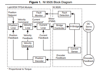
NI 9505 Hardware Overview
The NI 9505 provides unique flexibility and customization. The
NI 9505 works together with the LabVIEW FPGA Module to
create a highly customizable motor drive or actuator amplifier.
Figure 1 illustrates the functionality of the NI 9505 working in
conjunction with the LabVIEW FPGA Module in a typical motion
control application. Figures 2 and 3 show more detailed versions
of the position, velocity, and current loops implemented in the
LabVIEW FPGA Module. A typical application contains a
position loop, velocity loop, and current loop, implemented in
the LabVIEW FPGA Module block diagram. Depending on the
application, you may not need to use all three loops. The examples
installed in the labviewexamplesCompactRIOModule
SpecificNI 9505 directory illustrate methods for implementing
each of these loops.
The NI 9505 returns the motor or actuator current data to the
LabVIEW FPGA Module for use in a current loop or for
monitoring. The NI 9505 also returns status information such as
drive fault status, VSUP presence, and emergency stop status to the
LabVIEW FPGA Module for use in system monitoring. Refer
to the NI 9505 Reference Help book in the LabVIEW Help,
available by selecting Help»Search the LabVIEW Help, for
more information about the available status information.
The LabVIEW FPGA Module generates a PWM signal and sends
the signal to the NI 9505. The PWM signal is proportional to the
desired current or torque you want to provide to the motor or
actuator. Increasing the PWM duty cycle results in increased
current and thus increased torque.
Quadrature encoder signals pass through the NI 9505 and are
processed in the LabVIEW FPGA Module for use in the position
Hot-Swap Behavior
The NI 9505 is always disabled when it is inserted in the chassis,
regardless of whether VSUP is present or not. You can enable the
drive using the Enable Drive method in software. Refer to the
NI 9505 Reference Help book in the LabVIEW Help, available
by selecting Help»Search the LabVIEW Help, for more
information about enabling the drive.
When the NI 9505 is removed from the chassis while it is enabled,
the power to the motor is removed and the motor decelerates to a
stop based on its own friction.
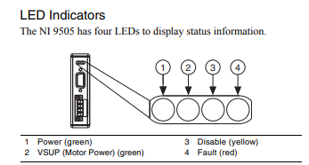
Power
The Power LED (green) illuminates when the NI 9505 is properly
inserted into a powered chassis.
Note The Power LED does not illuminate when the
chassis is in sleep mode.
VSUP
The VSUP LED (green) illuminates when the motor DC power
supply is properly connected and powering the drive.
Disable
The Disable LED (yellow) illuminates when the drive is disabled.
The drive is disabled by default at power-on. You can enable the
drive using the Enable Drive method in software. Refer to the
NI 9505 Reference Help book in the LabVIEW Help, available
by selecting Help»Search the LabVIEW Help, for more
information about this method.
Fault
Caution If the Fault LED is lit, determine the cause of the
fault and correct it before enabling the drive.
The Fault LED (red) illuminates when a fault occurs. A fault
disables the drive. Causes for fault are the following:
Caution VSUP greater than 40 V will result in damage to
the NI 9505.
• Overvoltage
• Undervoltage
• Motor terminal (MOTOR±) short to VSUP
• Motor terminal (MOTOR±) short to COM
• Module temperature exceeds 115 ºC
• Sending commands to the motor before enabling the drive
Note Do not command motor movement until the drive is
enabled with the Enable Drive method. Attempting to
control the motor before it is enabled will result in a fault.
• Violating PWM minimum pulse width requirements. Refer to
the Specifications section for more information about PWM.
Sleep Mode
This module supports a low-power sleep mode. Support for sleep
mode at the system level depends on the chassis that the module is
plugged into. Refer to the chassis manual for information about
support for sleep mode. If the chassis supports sleep mode, refer
to the software help for information about enabling sleep mode.
Visit ni.com/info and enter cseriesdoc for information about
C Series documentation.
Typically, when a system is in sleep mode, you cannot
communicate with the modules. In sleep mode, the system
consumes minimal power and may dissipate less heat than it does
in normal mode. Refer to the Specifications section for more
information about power consumption and thermal dissipation.
Wiring the NI 9505
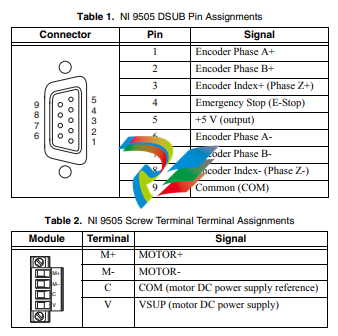
The NI 9505 has a 9-pin female DSUB connector that provides
connections for the encoder inputs, a +5 V connection for encoder
power, a connection for an emergency stop input, and a connection
to COM. Refer to Table 1 for the pin assignments.
The NI 9505 also has a screw terminal connector that provides
connections to a motor DC power supply and a DC brushed servo
motor. Connect the positive lead of the power supply to terminal 4,
VSUP, and the negative lead to terminal 3, COM. Refer to Table 2
for the terminal assignments.
Note You must use 2-wire ferrules to create a secure
connection when connecting more than one wire to a
single terminal on the NI 9505 screw terminal.
Caution Do not turn on or plug in the motor DC power
supply until the screw terminal connector is fully inserted.
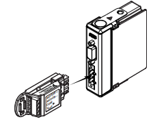
Optional Screw Terminal Accessory
Use the NI 9931 Screw Terminal Accessory instead of the
detachable screw terminal connector to increase the output power
of the module at temperatures below 70 ºC. The NI 9931 is
available from ni.com (NI part number 780571-01) or by calling
your National Instruments sales representative. Refer to the
Specifications section for more information. Refer to Figure 5 for
an illustration.
Figure 5. NI 9505 Module with Optional Screw Terminal Accessory
Wiring for High Vibration Applications
National Instruments recommends using ferrules to terminate
wires to the detachable screw terminal connector or the NI 9931
Screw Terminal Accessory when you use the NI 9505 in high
vibration applications. Refer to Figure 6 for an illustration.
Figure 6. 4-Terminal Screw Terminal Connector or
Accessory with a Ferrule
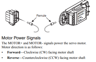
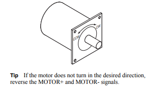
Motor Power Signals
The MOTOR+ and MOTOR- signals power the servo motor.
Motor direction is as follows:
• Forward—Clockwise (CW) facing motor shaft
• Reverse—Counterclockwise (CCW) facing motor shaf
Encoder Signals
The encoder signals consist of a Phase A, Phase B, and Index
(Phase Z) input. The NI 9505 supports differential and
single-ended inputs for Phase A, Phase B, and Index (Phase Z)
signals. Figures 8 and 9 show simplified schematic diagrams of the
encoder input circuit connected to differential and single-ended
inputs. You can also accommodate open-collector output encoders
by using a 1 kΩ pull-up resistor on each line to +5 VDC. Refer to
the Specifications section for more information about the encoder
inputs.
The encoder signals are raw digital input signals. These signals are
used in the LabVIEW FPGA Module for position and/or velocity
feedback. Figures 8 and 9 illustrate the use of the encoder signals
in a position and velocity loop in the LabVIEW FPGA Module.
Refer to the examples installed at labviewexamples
CompactRIOModule SpecificNI 9505 for examples of using
the encoder signals. Refer to the NI 9505 Reference Help book
in the LabVIEW Help, available by selecting Help»Search the
LabVIEW Help, for more information.
If the encoder cable length is greater than 3.05 m (10 ft), use
encoders with differential line driver outputs for your applications.
Power for a +5 V encoder—generated by a power supply inside the
NI 9505—is available on pin 5 of the DSUB connector.
Note The internal power supply is powered through the
Vsup pin.
Closed-loop servo applications require consistent directional
polarity between the motor and encoder for correct operation.
One industry-standard directional polarity is as follows:
• Positive = forward = clockwise (CW) facing motor shaft
• Negative = reverse = counterclockwise (CCW) facing motor
shaft
Refer to Figure 7 for a depiction of clockwise and
counterclockwise rotation. If encoder counting does not behave as
expected, change the encoder polarity in the FPGA or swap the
Phase A and Phase B connections.
When connecting the encoder wiring to the NI 9505, use shielded
wire of at least 24 AWG. You must use cables with twisted pairs
and an overall shield for improved noise immunity. Refer to
Figure 4 for a connection example.
Note Using an unshielded cable may produce noise,
which can corrupt the encoder signals and cause lost
counts, reduced accuracy, or other erroneous encoder and
drive operation.
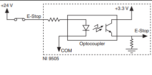
Emergency Stop Signal
The E-Stop signal is an input to the drive from an emergency stop
switch. Figure 10 shows a simplified schematic of the emergency
stop input circuit. When the emergency stop switch is closed,
current flows through the circuit, and the drive is enabled. When
an external event activates the emergency stop switch, the switch
opens and current stops flowing, disabling the drive. The E-Stop
functionality is disabled by default. Refer to the NI 9505 Reference
Help book in the LabVIEW Help, available by selecting Help»
Search the LabVIEW Help, for information about how to enable
this signal using the Enable E-Stop Property.
Figure 10. Emergency Stop Input Circuit
Cable Requirements for EMC Compliance
Use the following guidelines when selecting cables for the
NI 9505:
• Use shielded cables with a low impedance connection to
chassis ground to minimize noise and signal crosstalk.
• Tie the VSUP cable shield to chassis ground at the module side
only.
• Tie the motor cable shield to chassis ground at the motor side
only.
• Tie the encoder cable shield to COM at the encoder side only.
• Wire encoder signals and their ground connections separately
from all other connections to prevent lost encoder counts.
• Route wires along the machine frame to reduce high frequency
noise.
• Add clamp-on ferrites to cables to further reduce emissions.
• Add a balun to the power cable to attenuate conducted and
radiated emissions
Channel-to-COM ..............................0 to +30 VDC max,
Measurement Category I
Isolation
Channel-to-channel ....................None
Channel-to-earth ground
Continuous ...........................60 VDC,
Measurement Category I
Withstand .............................750 Vrms, verified by a 5 s
dielectric withstand test
Measurement Category I is for measurements performed on
circuits not directly connected to the electrical distribution system
referred to as MAINS voltage. MAINS is a hazardous live electrical
supply system that powers equipment. This category is for
measurements of voltages from specially protected secondary
circuits. Such voltage measurements include signal levels, special
equipment, limited-energy parts of equipment, circuits powered by
regulated low-voltage sources, and electronics.
Caution Do not connect the NI 9505 to signals or use for
measurements within Measurement Categories II, III, or IV.
CE Compliance
This product meets the essential requirements of applicable
European directives as follows:
• 2014/35/EU; Low-Voltage Directive (safety)
• 2014/30/EU; Electromagnetic Compatibility Directive (EMC)
• 94/9/EC; Potentially Explosive Atmospheres (ATEX)
Online Product Certification
Refer to the product Declaration of Conformity (DoC) for
additional regulatory compliance information. To obtain product
certifications and the DoC for this product, visit ni.com/
certification, search by module number or product line, and
click the appropriate link in the Certification column.
Shock and Vibration
To meet these specifications, you must panel mount the system and
affix ferrules to the end of the screw terminal wires.
Operating vibration
Random (IEC 60068-2-64).........5 grms, 10 to 500 Hz
Sinusoidal (IEC 60068-2-6) .......5 g, 10 to 500 Hz
Environmental Management
NI is committed to designing and manufacturing products in an
environmentally responsible manner. NI recognizes that
eliminating certain hazardous substances from our products is
beneficial to the environment and to NI customers.
For additional environmental information, refer to the Minimize
Our Environmental Impact web page at ni.com/environment.
This page contains the environmental regulations and directives
with which NI complies, as well as other environmental
information not included in this document.
Waste Electrical and Electronic Equipment (WEEE)
EU Customers At the end of the product life cycle,
all products must be sent to a WEEE recycling center.
For more information about WEEE recycling centers,
National Instruments WEEE initiatives, and compliance
with WEEE Directive 2002/96/EC on Waste and Electronic
Equipment, visit ni.com/environment/weee.
Worldwide Support and Services
The NI website is your complete resource for technical support. At
ni.com/support you have access to everything from
troubleshooting and application development self-help resources
to email and phone assistance from NI Application Engineers.
Visit ni.com/services for NI Factory Installation Services,
repairs, extended warranty, and other services.
Visit ni.com/register to register your NI product. Product
registration facilitates technical support and ensures that you
receive important information updates from NI.
A Declaration of Conformity (DoC) is our claim of compliance
with the Council of the European Communities using the
manufacturer’s declaration of conformity. This system affords the
⬉ᄤֵᙃѻક∵ᶧࠊㅵ⧚ࡲ˄ ⫣Ё RoHS˅
Ёᅶ᠋ National Instruments ヺড়Ё⬉ᄤֵᙃ
ѻકЁ䰤ࠊՓ⫼ᶤѯ᳝ᆇ⠽䋼ᣛҸ (RoHS)DŽ݇Ѣ
National Instruments Ё RoHS ড়㾘ᗻֵᙃˈ䇋ⱏᔩ
ni.com/environment/rohs_chinaDŽ (For information
about China RoHS compliance, go to ni.com/
environment/rohs_china.)
-
 AMAT 0100-00046 AC Current Sense PWB
 -
 AMAT A0414720 Precision Advanced System Controller
 -
 AMAT 0010-00017 Precision Semiconductor Process Interface
 -
 AMAT 01-82889-00 High-Performance Semiconductor Component
 -
 ABB Sample Gas Cooler SCC-C 23070-0-10232110
 -
 IBA ibaRackline-PCHD Efficient process analysis with ibaHD-Server
 -
IBA ibaRackline-PC CAM Frame-accurate video information with ibaCapture
-
IBA ibaRackline-PC Highly available and reliable
-
 IBA Optical Signal Multiplier ibaBM-FOX-i-3o-D
 -
 IBA Optical Data Distribution System ibaBM-DIS-i-8o
 -
IBA Optical Data Concentrator ibaBM-COL-8i-o
-
 IBA ibaNet750-BM-D Acquisition via FO
 -
 IBA ibaW-750 Acquisition via Ethernet
 -
 IBA ibaPADU-8AI-I Compact Measurement Modules
 -
 IBA ibaPADU-D-8AI-I Compact Measurement Modules
 -
 IBA ibaPADU-8AI-U Compact Measurement Modules
 -
 IBA ibaPADU-D-8AI-U Compact Measurement Modules
 -
 IBA ibaPADU-4-AI-U Compact Measurement Modules
 -
 IBA ibaPADU-C-8AI Self-Supplied Data Logger
 -
 IBA ibaBM-ENetIP Bus monitor for EtherNet/IP
 -
 IBA ibaBM-eCAT Bus monitor for EtherCAT
 -
 IBA ibaBM-DP Bus monitor for PROFIBUS
 -
 IBA ibaBM-PN: Bus monitor for PROFINET IO
 -
 IBA ibaMS3xAI-1A Precision AC Current Measurement Module
 -
 IBA ibaDAQ Intelligent Central Unit
 -
 IBA ibaPQU-S Power Quality Monitoring System
 -
 IBA ibaCMU-S Condition Monitoring Unit (CMU)
 -
 IBA ibaPADU-S-IT-2x16 Modular data acquisition and control system
 -
IBA ibaPADU-S-CM Modular data acquisition system
-
 IBA ibaM-4AI-IEPE Input module
 -
IBA ibaM-4AI-UI Input module
-
IBA ibaM-4AI-150V-AC Input module
-
 IBA ibaM-4AI-600V-AC Input module
 -
 IBA ibaLink-SM-256V: High-Density PLC Data Interface
 -
 IBA ibaLink-SM-64V High-Performance S5/S7 Interface
 -
IBA ibaLink-SM-128V-i-2o Synchronous Fiber Optic (ibaNet)
-
 IBA ibaLink-SM-128V communication module
 -
IBA ibaM-4AI-5A-150A-AC Input module
-
 IBA ibaM-FO-2IO Interface module
 -
 IBA ibaM-COM Communication module
 -
 IBA ibaM-DAQ Intelligent Processor Module
 -
 B&R ECE161-0 MULTI digital input module
 -
 B&R ECCP70-01 MULTI CPU type B 42 KByte SRAM
 -
 B&R ECCP60-01 MULTI CPU type B 42 KByte SRAM
 -
 B&R DI426 digital input module
 -
 B&R 2DS100.60-1 electronic drum sequencer Absolut encoder
 -
 B&R 2CP100.60-1 CPU MODULE
 -
 B&R 2BM100.9 High-performance I/O module
 -
 AMAT 0190-14928 SCR Power Controller (PVD Reverse Zone)
 -
 AMAT 0500-01065 300mm Loadlock Interface Interlock Board
 -
 AMAT 2000-21123 Advanced Vacuum Seal Assembly
 -
 AMAT 0660-00090 High-Performance Industrial Power Filter
 -
 AMAT 0240-34077 Centura Endpoint Controller Kit
 -
 AMAT 0195-10215 High-Precision Pedestal Assembly
 -
 AMAT 0190-76050 VGA Video Controller VME Module
 -
 AMAT 0190-75084 High-Performance Communication & Logic Controller
 -
 AMAT 0190-60287 Precision VME/cPCI Interface Control Module
 -
 AMAT 0190-53752 DI Water I/O Controller PCB
 -
 AMAT 0190-37993 DeviceNet Scanner Pro (3U CompactPCI)
 -
 AMAT 0190-37833 MKS CDN500R-5 EPI 300mm Interface Module
 -
AMAT 0190-37771 MKS CDN500R Interlock Control Module
-
 AMAT 0190-37616 High-Precision Analog Input/Output Interface
 -
 AMAT 0190-36787B ISAC CP I/O Block 2 (Top) - Revision B
 -
 AMAT 0190-36787 ISAC CP I/O Block 2 (Top)
 -
AMAT 0190-36511 DIP294 DeviceNet I/O Control Block
-
 AMAT 0190-35764 & 0190-35765: Precision Control Interface Duo
 -
 AMAT 0190-35763 High-Performance Integrated Power Module
 -
 Applied Materials (AMAT) 0190-34512 4-Channel DeviceNet Scanner Interface
 -
 Applied Materials (AMAT) 0190-34282 High-Stability Process Control Module
 -
Applied Materials (AMAT) 0190-27707 High-Precision DeviceNet I/O Controller
-
 Applied Materials (AMAT) 0190-27072 High-Performance Semiconductor Interface
 -
 AMAT 0190-24007 CPCI-3720CF Single Board Computer
 -
 AMAT 0190-23905 Spellman ESC High Voltage Power Supply
 -
 AMAT 0190-22967 High-Density Analog I/O Control Board
 -
 AMAT 0190-22543 High-Precision Analog Input/Output Module
 -
 AMAT 0190-17964 Etch DPS Interlock Module
 -
 AMAT 0190-17894 Interlock Module Conductor HART
 -
 AMAT 0190-17081 2U CompactPCI System Host Processor
 -
 AMAT 0190-16926 and 0190-16928 Based on Compact PCI
 -
AMAT 0190-15915 Intelligent I/O Control Module
-
 AMAT 0190-15840 4-Port UPA DeviceNet Interface Module
 -
 AMAT 0190-15384 Advanced Digital Signal Interface Module
 -
 AMAT 0190-14027 Wafer Flat Finder PCB
 -
 AMAT 0190-12695 SBS CL7 3U CompactPCI Single Board Computer
 -
 AMAT 0190-11817 CP3-SER16-TTL 16-Port Serial Interface Card
 -
 AMAT 0190-11524 CDN500-25 Interlock Module
 -
 AMAT 0190-07450 CompactPCI 48-Channel Digital I/O Interface Board
 -
 AMAT 0190-05990-001 Maglev Rotation System Controller (300mm)
 -
 AMAT 0190-05647 LK3710 Serial Module Transition Card
 -
 AMAT 0190-04457 High-Performance Integrated Circuit Control Module
 -
 Applied Materials (AMAT) 0190-04098 | 5.X Factory Interface I/O Distribution Board
 -
 Applied Materials (AMAT) 0190-03705 | MF Producer SE/E Interlock Module
 -
 Applied Materials (AMAT) 0190-02748 | Flex Scanner Transition Module
 -
 Applied Materials (AMAT) 0190-02362 | Mainframe Interlock 1 Relay Module
 -
 Applied Materials (AMAT) 0190-01227 | Intelligent Motor Control OMS Board
 -
 Applied Materials (AMAT) 0190-00318 | VME 486 Video Controller
 -
 Applied Materials (AMAT) 0130-14007 | Advanced RF Signal Assembly
 -
 Applied Materials (AMAT) 0130-14005 | RF Cable/Interface Assembly
 -
 Applied Materials (AMAT) 0130-01218 | High-Efficiency RF Interface Controller
 -
 Applied Materials (AMAT) 0110-77040 | Head Pneumatic Controller
 -
 Applied Materials (AMAT) 0110-00077 | Precision Control Module
 -
 AMAT 0101-57015 high-performance Next-Generation Deflection Amplifier Board
 -
 AMAT 0100-77040 critical Head Pneumatic Controller Board
 -
 AMAT 0100-76291 Data Buffer / Memory Expansion Interface
 -
 AMAT 0100-76290 Advanced I/O Interface Board
 -
 AMAT 0100-76269 Control Board / Interface Module
 -
 AMAT 0100-71462-01 high-performance Process Controller PCB
 -
 AMAT 0100-71171 Chamber Interlock Control PCB
 -
 AMAT 0100-71154 Semiconductor Circuit Board / Electronic Group Card
 -
 AMAT 0100-70034 PCB Assembly (PCBA) for Endpoint VGA I/O Interconnect.
 -
 AMAT 0100-38032 ESC (Electrostatic Chuck) Controller PCB
 -
 AMAT 0100-36035 DPS Source Match / Seriplex I/O Distribution PCB
 -
 AMAT 0100-35231 Seriplex I/O Distribution Module
 -
 AMAT 0100-35217 TC Amp Interlock PCB Module
 -
 AMAT 0100-35065 High-Precision Serial Isolator PCB
 -
 AMAT 0100-35054 Advanced Chamber Interface Module
 -
 AMAT 0100-20453 DeviceNet Digital I/O Interface Board
 -
 AMAT 0100-20100 High-Performance Semiconductor Component
 -
 AMAT 0100-20068 Precision CCD Image Control Board
 -
 AMAT 0100-20064 Advanced Semiconductor Control Module
 -
Applied Materials (AMAT) 0100-20018 Advanced Communication Interface Module
-
 Applied Materials (AMAT) 0100-20016 High-Performance Interface and Control Module
 -
 Applied Materials (AMAT) 0100-20003 Digital I/O (DI/DO) Interface Board
 -
 Applied Materials (AMAT) 0100-20001 System Electronics Interface (SEI) / PCB Assembly
 -
 Applied Materials (AMAT) 0100-11030 Chamber Hardware / Gas Distribution Component
 -
 Applied Materials (AMAT) 0100-11022 Semiconductor Board Card
 -
 Applied Materials (AMAT) 0100-11018 Advanced Interface Control Module
 -
 Applied Materials (AMAT) 0100-11001 Precision Analog Output Board


