
schneiderOperating Manual PacDrive™ C200 / C200 A2 Controller
About this manual
1.1 Introduction
Read and observe this manual before you work on the PacDrive Controller for the first
time. Take particular note of the safety instructions. As described in section 2.2, only
those persons who meet the "Selection and qualification of employees" are allowed to
work on the PacDrive Controller.
A copy of this manual must always be available for personnel who are entrusted to
work on the PacDrive Controller.
This manual is intended to help you use the PacDrive Controller and its intended ap‐
plications safely and properly.
By observing this manual, you will help to
• avoid risks,
• reduce repair costs and down times of the PacDrive Controller,
• increase the life span of the PacDrive Controller
• and increase reliability of the PacDrive Controller.
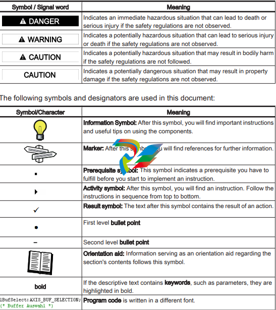
Symbols, designator and display format of safety notes
This manual divides the safety instructions into four various categories.
Hazards and possible results will be categorized using a certain combination of sym‐
bols and signal words.
Notes for working safely with the product
The PacDrive Controller is state of the art and conform to recognized technical safety
regulations. Nevertheless the use of the PacDrive Controller can present a hazard to
life and limb or cause property damage. The following section contains general re‐
quirements for safe work with the PacDrive Controller. Each person who uses or works
on the PacDrive Controller must read and follow these requirements.
2.1 Proper use
Use The PacDrive Controller is intended to be installed in a machine or assembled with
other components to form a machine or system.
What do you
need to ob‐
serve?
Proper use includes that you observe the following points and the resulting rules:
• The regulative, warning and instruction signs on the connected components and
in the switching cabinet
• The warning instructions on the PacDrive Controller on the connected components
and in the switch cabinet
• The inspection and maintenance instructions
• The operating instructions of the other components
• All other documentation
Flawless
State
Operate the PacDrive Controller only when they are in a flawless technical condition.
Observe the regulations, act with safety and hazards in mind If circumstances occur
that impact safety or cause changes in the operating performance of the PacDrive
Controller, switch the PacDrive Controller off immediately and contact the responsible
service staff.
Only original
equipment
must be used
Use only the options and mounting parts specified in the documentation and no thirdparty devices or components that are not expressly approved ELAU recommends. Do
not change the PacDrive Controller inappropriately.
Protection
measures
provide for
Before installing, provide for appropriate protective devices in compliance with the local
and national standards. Do not commission components without accordant protective
devices. After installation, commissioning or repair, test the protective devices used.
Forbidden
environments
The components must not be used in the following environments:
• In dangerous (explosive) atmospheres
• In mobile, movable or floating systems
• In life support systems
• In domestic appliances
Installation
and operating
ambient
You may only use them in accordance with the installation and operating conditions
described in the documentation. The operating conditions at the installation location
must be checked and maintained in accordance with the required technical data (per‐
formance data and ambient conditions). Commissioning is prohibited until it is guar‐
anteed that the usable machine or system in which the PacDrive Controller is installed
meets all requirements of EC Directive 98/37/EC (machinery directive).
In addition, the following standards, directives and regulations are to be observed:
• DIN EN 60204 Safety of machinery: Electrical equipment of machines
• DIN EN 292 Part 1 and Part 2 Safety of machinery: Basic Concepts, General Prin‐
ciples for Design
• DIN EN 50178 Electronic equipment for use in high-current electrical systems
• EMC directive 2004/108/EG
• The generally applicable local and national safety and accident prevention regu‐
lations.
• The rules and regulations on accident prevention and environmental protection that
apply in the country where the product is used
• The applicable laws and ordinances
2.2 Selection and qualification of personnel
Target Audi‐
ence
of this manual
This manual is geared exclusively toward technically qualified personnel, who have
detailed knowledge in the field of automation technology. The description is mainly for
construction and application engineers from the engineering and electro-technics di‐
vision as well as service and commissioning engineers.
Specialist or
trained
staff
Work on the PacDrive Controller may only be carried out by qualified professional or
by trained staff under the instruction and supervision of a qualified person in accord‐
ance with electrical regulations. Professionals are those persons who, as a result of
their training, knowledge, and experience and knowledge of the pertinent regulations,
can
• evaluate the transferred work,
• recognize the meaning of the safety instructions and implement them consistently,
• recognize possible hazards and
• take appropriate safety measures
Rest dangers
Health risks arising from the PacDrive Controller have been reduced by means of
safety technology and design engineering. However a residual risk remains, since the
PacDrive Controller works with electrical voltage and electrical currents.
If activities involve residual risks, a warning instruction is made at the appropriate
points. The note details the potential hazard and its effects and describes preventative
measures to avoid it.
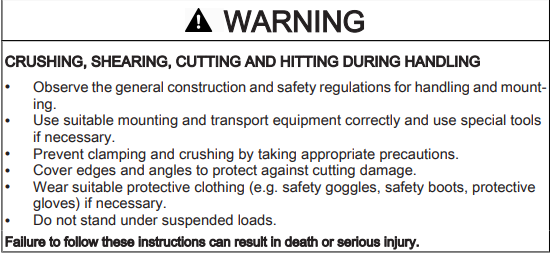
Mounting and handling
Touching electrical parts
DANGER
ELECTRIC SHOCK, FIRE OR EXPLOSION CAUSED BY HIGH VOLTAGE
• Observe the general construction and safety regulations for working on highcurrent electrical systems.
• After installation, check the firm connection of the ground conductor to all elec‐
trical units to ensure that connection complies with the connection diagram.
• Always make sure that the ground conductor is connected when operating elec‐
trical components.
• Before working on electrical equipment with a voltage greater than 50 volts, the
main switch has to be in the "OFF" position and secured, so it cannot be restarted.
• Disconnect devices with a voltage greater than 30 V rms or 42,2 V DC from the
power supply before working on electrical parts.
• Wait at least 5 minutes after switching off before accessing the components.
• Before working on the equipment, discharge the DC bus and use a voltage meter
to make sure that there is no voltage.
• Do not touch the electrical connection points of the components when the device
is switched on.
• Make sure that the drives are at a standstill because potentially fatal voltage can
occur on the motor lines in generator operation.
• Before enabling the device, safely cover the live components to prevent contact.
• Disconnect power connector cables only when the system is deactivated.
• Plug in power connector cables only when the system is deactivated.
• Provide for protection against indirect contact (DIN EN 50178, Section 5.3.2).
• If you are not using prefabricated ELAU cables, check that the assignment of the
new cables complies with the connection diagram of the machine manufacturer.
Failure to follow these instructions will result in death or serious injury.
Dangerous movements
There can be different causes of dangerous movements:
• Missing or faulty homing of the robot mechanics
• Wiring or cabling errors
• Errors in the application program
• Component errors
• Error in the measured value and signal transmitter
• Operation error
Personal safety must be guaranteed by primary equipment monitoring or measures.
Don't just rely on the internal monitoring of the drive components. Monitoring or meas‐
ures should be implemented based on the specific characteristics of the equipment,
in line with a risk and error analysis. This includes the valid safety regulations for the
equipment.
DANGER
DANGEROUS MOVEMENTS
• Prevent entry to a danger zone, e.g. by means protective fencing, mesh guards,
protective covers, or light barriers.
• Ensure the protective devices are properly dimensioned.
• Under no circumstances must the technical safety devices be removed.
• Do not make any modifications to a protective device that may put it out of op‐
eration.
• Protect existing work stations against unauthorized operation.
• Effectively restrict access to the control terminals to allow access only to author‐
ized persons.
• Position EMERGENCY OFF switches so that they are easily accessible and can
be reached quickly.
• Check the functionality of EMERGENCY OFF equipment before start-up and
during maintenance periods.
• Prevent unintentional start-ups by disconnecting the drives from power supply
using the EMERGENCY OFF circuit or using a safe start-up lock out.
• Before accessing the drives or entering the danger zone, safely bring the drives
to a stop.
• While working on the system, power down the electrical equipment using the
main switch and prevent it from being switched back on.
• Secure the system from being switched back on before working on it.
• Avoid operating high-frequency, remote control, and radio devices close to the
system electronics and their feed lines.
• Prior to the initial start-up, check the system and the installation for possible mal‐
functions in all usage scenarios.
• If necessary, carry out a special EMC check of the system.
Failure to follow these instructions will result in death or serious injury
Safe separated extra-low voltage"
PELV Protec‐
tive Extra-Low
Voltage
The signal voltage and control voltage of the PacDriveTM devices are <33 Volts. In this
range, the specification as a PELV system in accordance with IEC 60364-4-41 in‐
cludes a protective measure to guard against direct and indirect contact with danger‐
ous voltage through the safe separation of the primary and secondary sides in the
system/machine. ELAU strongly recommends providing the system/machine with safe
isolation.
DANGER
HIGH ELECTRICAL VOLTAGE DUE TO INCORRECT CONNECTION
• Please ensure that only devices, electrical components or lines that have suffi‐
cient, safe electrical separation from the connected circuits in accordance with
the standards (EN 50178 / 1998 edition - Electronic equipment for use in power
stations) are connected to the signal voltage connectors of this component.
• Ensure that the existing electrical separation is maintained throughout the entire
circuit.
Failure to follow these instructions will result in death or serious injury
FELV Function‐
al Extra-Low
Voltage
When using ELAU Components in systems that do not have safe separation as a
protective measure against direct or indirect contact of dangerous voltages, all con‐
nections and contacts (e.g. PacDrive Controller, Sub-D connector, serial interface) that
do not meet protection class IP2X require a permanent cover. The cover or the device
connection of the connected device must be designed so that it can only be removed
by using a tool. The protective measures have to be adhered on all connected devices
Indicators, control elements, diagnosis
The PacDrive™ System supports the user with its comprehensive diagnostic sys‐
tem.
The diagnostic messages can be read out with the Automation Toolkit EPAS-4 . The
PacDrive™ System contains a powerful message logger in which additional diagnostic
information is recorded.
Diagnostic messages are usually displayed by a control panel on the machine. If an
"error" occurs, read the diagnostic message on this unit and then contact the machine
manufacturer.
Detailed information on diagnosis is available in the Online Help of the Automation
Toolkit EPAS-4.
3.1 Indicators on the PacDrive C200 Controller
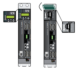
If the cover of the PacDrive Controller is closed, you will see four vertically arranged
indicators, which signal different operating- or error conditions.
• pow (control voltage indicator)
• wd (watchdog indicator)
• err (error display)
• bus err (SERCOS real-time bus error indicator)
V00.24.23
10.128.2111.103
0406-0117.0601
enter
In addition to the LED displays, you will receive further information about the operating
status of the PacDrive Controller via the 2-line LCD display.
Line 1 currently used firmware version
Line 2 current IP number of the PacDrive Controller
The horizontal arranged buttons have no function on the PacDrive Controller currently.
pow (control voltage display)
The "pow" LED indicates the state of the control voltage.
OFF The control voltage (24 V DC) is not available or too low.
ON Normal operation; control voltage in normal range
Flashes UPS active
wd (watchdog indicator)
Watchdog is a hardware module to monitor the controller.
OFF Normal operation
ON Fatal error; reset required, reboot system
A "fatal error" is a serious hardware problem or an unexpected software problem.
When a "fatal error" occurs
• the CPU is stopped,
• the optional module is reset,
• the outputs are reset and
• the wd (watchdog) relay outputs are opened.
err (error display)
The error LED (err) indicates errors. The following table lists the possible display con‐
ditions and their accompanying error descriptions.
OFF Normal operation
Flashes slowly (1.7 Hz) Error of class 1, 2, 3, 4 or 5 active
Flashes quickly (10 Hz) The boot of the PacDrive Controller is completed, the last boot failed.
See diagnostic message 209 "last boot failed". The PacDrive Controller
performed a minimal boot.
Flashes fast and slowly alter‐
nately
Firmware download via SERCOS is active
ON A serious error occurred during the current boot.
The err-LED is switched on following "Power on". Once the operating system, user
configuration, user parameters and the IEC program have been loaded and the IEC
program has been started successfully the err LED will switch off again. The boot
procedure is now complete.
bus err (SERCOS real-time bus error indicator)
OFF Normal operation
ON Bus error (problem with fiber-optic cable connection, e.g. transmitting
power is too low or too high, cable break, etc.)
Ethernet LEDs (data throughput indicator and network activity)
On the Ethernet connection (X10) of the PacDrive Controller two LED’s are indicated.
LED yellow: ON PacDrive Controller connected
LED yellow: flashing/flickering Current network traffic
LED yellow: OFF PacDrive Controller not connected
LED green: ON 100 MB connection
LED green: OFF 10 MB connection
After opening the operating cover you have access to the control elements of the Pac‐
Drive Controller:
• CompactFlashTM card slot
• Battery compartment
• [on / off] button
• [reset] button
3.2 CompactFlashTM card slot
The CompactFlash™ card slot is the entry for the permanent data memory (CF™ card)
of the PacDrive Controller.
▶ Switch off the PacDrive Controller.
▶ Hold the CF™ card with your thumb and forefinger and pull it out of the slot.
▶ To insert, carefully place the CF™ card on the guide rail and push it into the device.
▶ Push lightly until the card clicks in.
3.3 Battery compartment
battery
The battery of the PacDrive Controller buffers controller data (Bios, NVRAM, time,
etc.).
Maintenanceinterval
The battery should be replaced every 6 years. After this period of time the battery must
be replaced. If the device (with battery inserted) is not used for an extended period of
time, you should check/replace the battery.
Measurement This is how you measure the battery:
▶ Replace battery and continue with the manual measurement
or
▶ observe the diagnostic message "037 Battery down“ in the IEC program and dis‐
play it on an HMI (panel), if necessary.
▶ Replace battery three days after the first diagnostic message at the latest.
This is how you replace the battery:
▪ You can exchange the battery while the controller is on or off. There is no data
loss if it is performed while the controller is on. When the controller is switched off,
the time period of the data buffering without a battery is approx. 5 minutes.
WARNING
THERE IS A RISK OF EXPLOSION/FIRE IF THE WRONG BATTERY IS USED
• Only use the type of battery with the following data: 3V Lithium Renata Type
2450N.
Failure to follow these instructions can result in death or serious injury
Use insulated pliers to lightly pull the old battery out of its slot.
CAUTION
DANGER OF EXPLOSION WHEN REMOVING/REPLACING BATTERY
• Use a pair of suitable, insulated pliers.
• When replacing the battery use tools which contain no current conducting
material on the contact points.
• In general, be careful not to short circuit the battery poles.
• Do not recharge, dismantle or place battery in fire.
A non-observance of these instructions can cause bodily injury or damage the equipment.
▶ Carefully place the new battery on the guide and lightly push it into the device.
For ordering information (see 5.6 Type code).
3.4 On- /off / reset of the PacDrive Controller
reset
[reset] button
▶ Press this button to reset the controller and reboot it.
Connected Servo Amplifiers MC-4 have their own [reset] button.
-
 AMAT 0190-17081 2U CompactPCI System Host Processor
 -
 AMAT 0190-16926 and 0190-16928 Based on Compact PCI
 -
AMAT 0190-15915 Intelligent I/O Control Module
-
 AMAT 0190-15840 4-Port UPA DeviceNet Interface Module
 -
 AMAT 0190-15384 Advanced Digital Signal Interface Module
 -
 AMAT 0190-14027 Wafer Flat Finder PCB
 -
 AMAT 0190-12695 SBS CL7 3U CompactPCI Single Board Computer
 -
 AMAT 0190-11817 CP3-SER16-TTL 16-Port Serial Interface Card
 -
 AMAT 0190-11524 CDN500-25 Interlock Module
 -
 AMAT 0190-07450 CompactPCI 48-Channel Digital I/O Interface Board
 -
 AMAT 0190-05990-001 Maglev Rotation System Controller (300mm)
 -
 AMAT 0190-05647 LK3710 Serial Module Transition Card
 -
 AMAT 0190-04457 High-Performance Integrated Circuit Control Module
 -
 Applied Materials (AMAT) 0190-04098 | 5.X Factory Interface I/O Distribution Board
 -
 Applied Materials (AMAT) 0190-03705 | MF Producer SE/E Interlock Module
 -
 Applied Materials (AMAT) 0190-02748 | Flex Scanner Transition Module
 -
 Applied Materials (AMAT) 0190-02362 | Mainframe Interlock 1 Relay Module
 -
 Applied Materials (AMAT) 0190-01227 | Intelligent Motor Control OMS Board
 -
 Applied Materials (AMAT) 0190-00318 | VME 486 Video Controller
 -
 Applied Materials (AMAT) 0130-14007 | Advanced RF Signal Assembly
 -
 Applied Materials (AMAT) 0130-14005 | RF Cable/Interface Assembly
 -
 Applied Materials (AMAT) 0130-01218 | High-Efficiency RF Interface Controller
 -
 Applied Materials (AMAT) 0110-77040 | Head Pneumatic Controller
 -
 Applied Materials (AMAT) 0110-00077 | Precision Control Module
 -
 AMAT 0101-57015 high-performance Next-Generation Deflection Amplifier Board
 -
 AMAT 0100-77040 critical Head Pneumatic Controller Board
 -
 AMAT 0100-76291 Data Buffer / Memory Expansion Interface
 -
 AMAT 0100-76290 Advanced I/O Interface Board
 -
 AMAT 0100-76269 Control Board / Interface Module
 -
 AMAT 0100-71462-01 high-performance Process Controller PCB
 -
 AMAT 0100-71171 Chamber Interlock Control PCB
 -
 AMAT 0100-71154 Semiconductor Circuit Board / Electronic Group Card
 -
 AMAT 0100-70034 PCB Assembly (PCBA) for Endpoint VGA I/O Interconnect.
 -
 AMAT 0100-38032 ESC (Electrostatic Chuck) Controller PCB
 -
 AMAT 0100-36035 DPS Source Match / Seriplex I/O Distribution PCB
 -
 AMAT 0100-35231 Seriplex I/O Distribution Module
 -
 AMAT 0100-35217 TC Amp Interlock PCB Module
 -
 AMAT 0100-35065 High-Precision Serial Isolator PCB
 -
 AMAT 0100-35054 Advanced Chamber Interface Module
 -
 AMAT 0100-20453 DeviceNet Digital I/O Interface Board
 -
 AMAT 0100-20100 High-Performance Semiconductor Component
 -
 AMAT 0100-20068 Precision CCD Image Control Board
 -
 AMAT 0100-20064 Advanced Semiconductor Control Module
 -
Applied Materials (AMAT) 0100-20018 Advanced Communication Interface Module
-
 Applied Materials (AMAT) 0100-20016 High-Performance Interface and Control Module
 -
 Applied Materials (AMAT) 0100-20003 Digital I/O (DI/DO) Interface Board
 -
 Applied Materials (AMAT) 0100-20001 System Electronics Interface (SEI) / PCB Assembly
 -
 Applied Materials (AMAT) 0100-11030 Chamber Hardware / Gas Distribution Component
 -
 Applied Materials (AMAT) 0100-11022 Semiconductor Board Card
 -
 Applied Materials (AMAT) 0100-11018 Advanced Interface Control Module
 -
 Applied Materials (AMAT) 0100-11001 Precision Analog Output Board
 -
 Applied Materials (AMAT) 0100-11000 High-Precision Analog Input Board
 -
 Applied Materials (AMAT) 0100-09237 Advanced Signal Interface Module
 -
 Applied Materials (AMAT) 0100-09204 Advanced Digital Interface Control Board
 -
 Applied Materials (AMAT) 0100-09172 High-Density Digital I/O Control Board
 -
 Applied Materials (AMAT) 0100-09137 High-Performance VME Control Module
 -
 Applied Materials (AMAT) 0100-09054 Precision Analog Input Board
 -
 Applied Materials (AMAT) 0100-09029 Turbo Interconnect Interface Module
 -
 AMAT 0100-03391 Precision Semiconductor Control
 -
 AMAT 0100-01984 | VME System Interface & Logic Controller Board
 -
 AMAT 0100-01363 | VME Intelligent System Control & I/O Board
 -
 AMAT 0100-01321 | VME DeviceNet Scanner / Interface Board
 -
AMAT 0100-00793 | VME Multi-Channel Interface & Logic Board
-
 AMAT 0100-00689 | VME PCB Power Module
 -
 AMAT 0100-00580 | VME Intelligent System Controller Board
 -
 AMAT 0100-00523 | VME Multi-Channel Analog-to-Digital (A/D) Board
 -
 AMAT 0100-00493 | VME Multi-Function System Controller Board
 -
 AMAT 0100-00398 | VME Interface System Control Board
 -
 AMAT 0100-00369 | VME 12-Channel High-Speed Stepper Motor Controller
 -
 AMAT 0100-00196 | VME System Mainframe CPU Controller Board
 -
 AMAT 0100-00169 | VME 12-Channel Stepper Motor Controller Board
 -
 AMAT 0100-00162 | VME Dual Channel Serial Communication Board
 -
 AMAT 0100-00137 | VME Stepper Motor Controller Interface Board
 -
 AMAT 0100-00075 | VME Digital Input/Output (DI/O) Interface Board
 -
 AMAT 0100-00007 VME Analog Input/Output Interface Board
 -
 AMAT 0100-00002 | VME Slave I/O Interface PCB
 -
 AMAT 0090-05596 High-Voltage DC Power Cable Assembly
 -
 AMAT 0090-01809 | High-Performance RF Power Cable Assembly
 -
 AMAT 0010-29958 | CCM HART 3 Mainframe Control Assembly
 -
 AMAT 0010-20003 System Controller Card Cage Assembly
 -
.png) AMAT 0010-11239 PVD High-Voltage Power Interface Assembly
AMAT 0010-11239 PVD High-Voltage Power Interface Assembly -
 AMAT 0010-09416 RF Matching Network Assembly
 -
 AMAT 0010-00019 Analog Power Supply Assembly
 -
 AMAT AS00009-02 (31-000-00940) | Precision Semiconductor Component
 -
 AMAT 0010-00028 Power Supply Module
 -
 AMAT 0330-1586A Serial Communication PCB
 -
 AMAT 0190-09690 Seriplex SENSORbus SPX-MUXADIO-001
 -
 AMAT 0190-04397 DeviceNet I/O Interface Board
 -
 AMAT 0190-02506 DeviceNet I/O Interface Card
 -
 AMAT 0090-00475 Seriplex 210 MUXADIO
 -
 AMAT 410-0198-1 Multi-Output Switching Power Supply
 -
 AMAT 0100-20458 high-reliability Configurable Interlock Personality Board
 -
 AMAT VAS104350-0415 Gasline Heater Control Unit
 -
 AMAT VME6U1V2 VMEbus Backplane Interface Module
 -
AMAT 0920-01070 high-performance RF Power Generator
-
 AMAT 0090-76133A VME Single Board Computer (SBC)
 -
 AMAT 0190-24115 DeviceNet I/O Interface Card
 -
 AMAT 0190-37607 Backplane / Base Board Assembly
 -
 AMAT 0190-32372 Analog Input/Output (I/O) Board
 -
 AMAT 0190-09956 Loadlock Interface PCB Base Assembly
 -
 AMAT 0190-07908 four-channel DeviceNet Interface Card
 -
 AMAT 0190-07905 (UPS) control board
 -
 AMAT 0190-07502 Precision Controller / Interface Board
 -
 AMAT 0190-03680 I/O Backplane
 -
 AMAT 0190-02200 Water Leak Detection Control Board
 -
 AMAT 0100-76124 Digital I/O Board Assembly
 -
 AMAT 0100-35563 Leak Detector Configuration PCB
 -
 AMAT 0100-35250 Chamber Interface DPS Centura PCB
 -
 AMAT 0100-35124 Seriplex I/O Distribution Board
 -
 AMAT 0100-35058 Loadlock Interlocks PCB
 -
 AMAT 0100-20213 RF Match Detector PCB
 -
 AMAT 0100-20063 Interface PCB Assembly
 -
 AMAT 0100-09225 TC AMP/INTERLOCK PCB
 -
 AMAT 0100-09153 Gas Panel Interface PCB
 -
 AMAT 0100-09127 Loader Interconnect Board
 -
 AMAT 0100-09009 Buffer I/O PCB Card
 -
 AMAT 0100-02813 Signal Conditioning Board
 -
 AMAT 0100-01911 AC Gas Heater Control Board
 -
 AMAT 0100-01708 Pedestal Integration PCB
 -
 AMAT 0100-00658 300mm RTP Controller Distribution PCB
 -
 AMAT 0100-00582 Gas Panel Controller Backplane
 -
 AMAT 0100-00049 Analog Signal Conditioner
 -
 AMAT 0100-00008 Control Interface Module
 -
 AMAT 0090-03402 DC Power Supply / Power Module
 -
 AMAT 0090-01248 DC Power Supply / Power Module
 -
 AMAT 0090-76109 RF Matching / Capacitor Assembly
 -
 AMAT 0101-57106 Substrate Voltage Board
 -
 AMAT 0101-57014 Deflection-Amplifier PCB


