
GEFanuc Automation Programmable Control Products
Warnings, Cautions, and Notes
as Used in this Publication
Warning
Warning notices are used in this publication to emphasize that hazardous voltages,
currents, temperatures, or other conditions that could cause personal injury exist in this
equipment or may be associated with its use.
In situations where inattention could cause either personal injury or damage to
equipment, a Warning notice is used.
Caution
Caution notices are used where equipment might be damaged if care is not taken.
Note
Notes merely call attention to information that is especially significant to understanding and
operating the equipment.
This document is based on information available at the time of its publication. While efforts
have been made to be accurate, the information contained herein does not purport to cover all
details or variations in hardware or software, nor to provide for every possible contingency in
connection with installation, operation, or maintenance. Features may be described herein
which are not present in all hardware and software systems. GE Fanuc Automation assumes no
obligation of notice to holders of this document with respect to changes subsequently made.
GE Fanuc Automation makes no representation or warranty, expressed, implied, or statutory
with respect to, and assumes no responsibility for the accuracy, completeness, sufficiency, or
usefulness of the information contained herein. No warranties of merchantability or fitness for
purpose shall apply.
The following are trademarks of GE Fanuc Automation North America, Inc.
Alarm Master Genius PowerTRAC Series Six
CIMPLICITY Helpmate ProLoop Series Three
CIMPLICITY 90–ADS Logicmaster PROMACRO VersaMax
CIMSTAR Modelmaster Series Five VersaPoint
Field Control Motion Mate Series 90 VersaPro
GEnet PowerMotion Series One VuMaster
Workmaster
©Copyright 2002 GE Fanuc Automation North America, Inc.
All Rights Reserved.
Content of This Manual
This manual describes Field Control I/O modules and associated components.
Chapter 1. Introduction: Chapter 1 provides basic information about the Field Control family
of products.
Chapter 2. Installation: Chapter 2 summarizes installation instructions for Field Control I/O
modules. I/O Terminal Blocks, and cables.
Chapters 3—end. I/O Module Datasheets: The rest of the manual consists of datasheets for
individual I/O modules.
Appendix A. Analog Signal Terms: Appendix A provides some definitions of basic analog
terms.
Appendix B. Scaling Analog Channels: Appendix A summarizes instructions for analog scaling.
Related Publications
For more information, refer to:
Field Control Genius Bus Interface Unit User’s Manual (GFK-0825). This book describes the
module that interfaces a group of Field Control I/O modules to a Genius serial bus. It explains how
to install and configure a Bus Interface Unit, and describes how a Bus Interface Unit operates.
Field Control FIP Bus Interface Unit User’s Manual (GFK-1175). This book describes the
module that interfaces a group of Field Control I/O modules to a FIP bus. It explains how to install
and configure a Bus Interface Unit, and describes how a Bus Interface Unit operates.
Field Control Profibus Bus Interface Unit User’s Manual (GFK-1291). This book describes the
module that interfaces a group of Field Control I/O modules to a Profibus. It explains how to install
and configure a Bus Interface Unit, and describes how a Bus Interface Unit operates.
This chapter provides basic information about Field Control I/O products.
Overview
Field Control is a family of versatile, truly modular I/O products, suitable for use in a wide range of
control system architectures.
Field Control I/O Modules are small and rugged. They provide easily-configurable discrete and
analog I/O interfaces which may also include local intelligence for signal processing.
I/O Terminal Blocks provide universal field wiring terminals for two I/O modules, allowing I/O
module types to be mixed on the same I/O Terminal Block. The I/O Terminal block is mounted on
a DIN rail. The DIN rail, which is an integral part of the grounding system, must be mounted to a
panel.
As many as eight Field Control I/O modules (four I/O terminal blocks) can be connected to one
Bus Interface Unit. Together, they make up a Field Control “station” Bus Interface Units are
available for different types of busses, such as Genius, Profibus, and FIP.

The Bus Interface Unit provides the I/O scanning, diagnostics, and communications capabilities
needed to link the I/O modules to the control system. In addition, the Bus Interface Unit may
provide (and store) configurable characteristics for I/O modules, such as fault reporting, output
defaults, analog range selection, and analog scaling
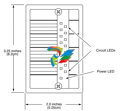
Field Control I/O modules are small rugged components with sturdy aluminum housings.
Modules are approximately 3.25 inches (8.2 cm) high x 2 inches (5.25 cm) wide. They are 2.90
inches (7.3 cm) deep (not including the portion that extends into the I/O Terminal Block).
Both discrete and analog conventional input and output modules are available. In addition,
intelligent modules, which perform more advanced functions, are also available. Examples of
intelligent modules are the Micro Field Processor, the 16-point Grouped Analog Input module
(IC670ALG240), the Thermocouple Input module (IC670ALG630), and the RTD Input module
(IC670ALG620).
LEDs
I/O Module LEDs are easily visible through the transparent central portion of the label. All
modules have an LED that indicates the presence of module power. Discrete modules also have
individual circuit LEDs that show the on/off status of each input or output circuit.
Front Label
The module's front label, shown above, has space for writing circuit identifications.
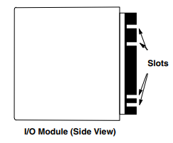
Module Keying
Each type of I/O module is slotted to allow keying. Small key clips (provided) can be inserted into
corresponding slots in the I/O base to assure that the module installed in that location will not cause
damage or unexpected machine operation. Actual keying slots are the same for some types of
modules.
For More Information About I/O Modules, See:
• Chapter 2, Installation.
• The I/O module datasheets in this manual.
• Configuration instructions in the Bus Interface Unit User's Manual.
Environmental Specifications
Vibration Modules perform well where vibration is a factor. Designs are shock and
vibration tested to meet the following specifications when installed on a panelmounted DIN rail using the clamp supplied, and with the panel-mounting feet
secured:
IEC68-2-6: 10 to 57 Hz 0.012 in displacement (peak to peak)
57 to 500 Hz at 2 g (unless otherwise specified)
IEC68-2-27: Shock: 15G, 11 milliseconds, half sine wave
Noise Modules are resistant to noise levels found in most industrial applications
when installed according to accepted practices, including proper separation of
wiring by voltage and power levels, on a conductive (unpainted) DIN rail. The
DIN rail is an integral part of the grounding system.
Modules are tested to the specifications listed in the Conformance to Standards
document (GFK-1079).
Temperature Modules operate reliably in ambient air temperatures from 0°C (32°F) up to
55°C (131°F).
Storage temperatures are -40°C (-40°F) to +85°C (185°F).
Humidity 5% to 95%, non-condensing
I/O Terminal Blocks
I/O Terminal Blocks are generic wiring bases for Field Control I/O modules. They provide I/O
module mounting, backplane communications, and terminals for user connections.
Two I/O modules can be installed on an I/O Terminal Block. Modules screw onto the terminal
block for vibration resistance.
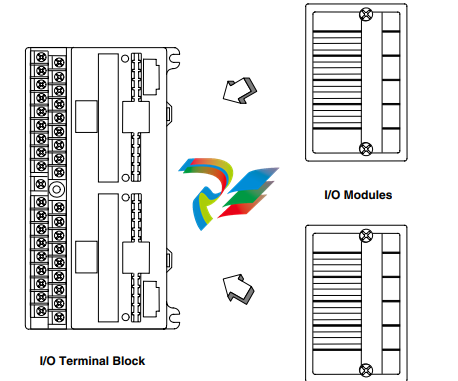
I/O modules can be removed from the I/O Terminal Block without disturbing field wiring
O Terminal Block General Description
The following illustration shows the basic parts of an I/O Terminal Block.
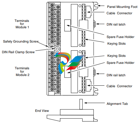
The I/O Terminal Block has two separate sets of module terminals. Each set corresponds to a
“slot” in a conventional rack-type PLC. Terminal wiring assignments depend on the I/O module
type installed in that location.
The grounding screw is used to attach a ground wire to the terminal block.
The cable connectors provide easy attachment of the cable that carries communications signals
between terminal blocks and the Bus Interface Unit.
The spare fuse holders can be used to store extra fuses (if needed) for the I/O modules.
The DIN rail latches clip the I/O Terminal Block to a DIN rail. Pulling these latches outward
releases the DIN rail.
The keying slots permit protective keying. Inserting the key clips provided into these slots assures
that the module installed in that location will not cause damage or unexpected machine operation.
I/O Terminal Blocks IC670CHS101, 102, and 103 have projecting alignment tabs designed to
facilitate Hot Insertion/Removal of modules. I/O Terminal Blocks IC670CHS001, 002, and 003,
which lack alignment tabs, do not support Hot Insertion/Removal of modules.
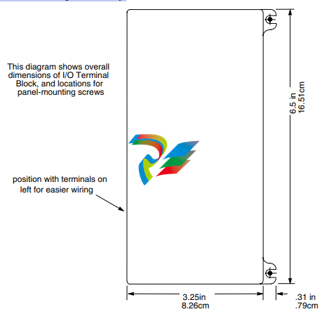
nstallation
The I/O Terminal Block can be installed in any orientation; the preferred vertical orientation for
easier wiring installation is with the wiring terminals on the left and the panel-mounting feet on the
right as shown below. The preferred horizontal orientation is with the wiring terminals at the
bottom and the mounting feet at the top.
Field Control terminal blocks must be installed on a 35mm x 7.5mm DIN rail, which becomes an
integral part of the grounding system. The DIN rail finish must be electrically conductive. The
DIN rail must not be painted.
The DIN rail should be mounted on a panel for added vibration resistance.
The overall depth of Field Control modules when mounted on terminal blocks and installed on a
35mm x 7.5mm DIN rail is 4.0 inches (10.16 cm).
-
 AMAT 0100-00046 AC Current Sense PWB
 -
 AMAT A0414720 Precision Advanced System Controller
 -
 AMAT 0010-00017 Precision Semiconductor Process Interface
 -
 AMAT 01-82889-00 High-Performance Semiconductor Component
 -
 ABB Sample Gas Cooler SCC-C 23070-0-10232110
 -
 IBA ibaRackline-PCHD Efficient process analysis with ibaHD-Server
 -
IBA ibaRackline-PC CAM Frame-accurate video information with ibaCapture
-
IBA ibaRackline-PC Highly available and reliable
-
 IBA Optical Signal Multiplier ibaBM-FOX-i-3o-D
 -
 IBA Optical Data Distribution System ibaBM-DIS-i-8o
 -
IBA Optical Data Concentrator ibaBM-COL-8i-o
-
 IBA ibaNet750-BM-D Acquisition via FO
 -
 IBA ibaW-750 Acquisition via Ethernet
 -
 IBA ibaPADU-8AI-I Compact Measurement Modules
 -
 IBA ibaPADU-D-8AI-I Compact Measurement Modules
 -
 IBA ibaPADU-8AI-U Compact Measurement Modules
 -
 IBA ibaPADU-D-8AI-U Compact Measurement Modules
 -
 IBA ibaPADU-4-AI-U Compact Measurement Modules
 -
 IBA ibaPADU-C-8AI Self-Supplied Data Logger
 -
 IBA ibaBM-ENetIP Bus monitor for EtherNet/IP
 -
 IBA ibaBM-eCAT Bus monitor for EtherCAT
 -
 IBA ibaBM-DP Bus monitor for PROFIBUS
 -
 IBA ibaBM-PN: Bus monitor for PROFINET IO
 -
 IBA ibaMS3xAI-1A Precision AC Current Measurement Module
 -
 IBA ibaDAQ Intelligent Central Unit
 -
 IBA ibaPQU-S Power Quality Monitoring System
 -
 IBA ibaCMU-S Condition Monitoring Unit (CMU)
 -
 IBA ibaPADU-S-IT-2x16 Modular data acquisition and control system
 -
IBA ibaPADU-S-CM Modular data acquisition system
-
 IBA ibaM-4AI-IEPE Input module
 -
IBA ibaM-4AI-UI Input module
-
IBA ibaM-4AI-150V-AC Input module
-
 IBA ibaM-4AI-600V-AC Input module
 -
 IBA ibaLink-SM-256V: High-Density PLC Data Interface
 -
 IBA ibaLink-SM-64V High-Performance S5/S7 Interface
 -
IBA ibaLink-SM-128V-i-2o Synchronous Fiber Optic (ibaNet)
-
 IBA ibaLink-SM-128V communication module
 -
IBA ibaM-4AI-5A-150A-AC Input module
-
 IBA ibaM-FO-2IO Interface module
 -
 IBA ibaM-COM Communication module
 -
 IBA ibaM-DAQ Intelligent Processor Module
 -
 B&R ECE161-0 MULTI digital input module
 -
 B&R ECCP70-01 MULTI CPU type B 42 KByte SRAM
 -
 B&R ECCP60-01 MULTI CPU type B 42 KByte SRAM
 -
 B&R DI426 digital input module
 -
 B&R 2DS100.60-1 electronic drum sequencer Absolut encoder
 -
 B&R 2CP100.60-1 CPU MODULE
 -
 B&R 2BM100.9 High-performance I/O module
 -
 AMAT 0190-14928 SCR Power Controller (PVD Reverse Zone)
 -
 AMAT 0500-01065 300mm Loadlock Interface Interlock Board
 -
 AMAT 2000-21123 Advanced Vacuum Seal Assembly
 -
 AMAT 0660-00090 High-Performance Industrial Power Filter
 -
 AMAT 0240-34077 Centura Endpoint Controller Kit
 -
 AMAT 0195-10215 High-Precision Pedestal Assembly
 -
 AMAT 0190-76050 VGA Video Controller VME Module
 -
 AMAT 0190-75084 High-Performance Communication & Logic Controller
 -
 AMAT 0190-60287 Precision VME/cPCI Interface Control Module
 -
 AMAT 0190-53752 DI Water I/O Controller PCB
 -
 AMAT 0190-37993 DeviceNet Scanner Pro (3U CompactPCI)
 -
 AMAT 0190-37833 MKS CDN500R-5 EPI 300mm Interface Module
 -
AMAT 0190-37771 MKS CDN500R Interlock Control Module
-
 AMAT 0190-37616 High-Precision Analog Input/Output Interface
 -
 AMAT 0190-36787B ISAC CP I/O Block 2 (Top) - Revision B
 -
 AMAT 0190-36787 ISAC CP I/O Block 2 (Top)
 -
AMAT 0190-36511 DIP294 DeviceNet I/O Control Block
-
 AMAT 0190-35764 & 0190-35765: Precision Control Interface Duo
 -
 AMAT 0190-35763 High-Performance Integrated Power Module
 -
 Applied Materials (AMAT) 0190-34512 4-Channel DeviceNet Scanner Interface
 -
 Applied Materials (AMAT) 0190-34282 High-Stability Process Control Module
 -
Applied Materials (AMAT) 0190-27707 High-Precision DeviceNet I/O Controller
-
 Applied Materials (AMAT) 0190-27072 High-Performance Semiconductor Interface
 -
 AMAT 0190-24007 CPCI-3720CF Single Board Computer
 -
 AMAT 0190-23905 Spellman ESC High Voltage Power Supply
 -
 AMAT 0190-22967 High-Density Analog I/O Control Board
 -
 AMAT 0190-22543 High-Precision Analog Input/Output Module
 -
 AMAT 0190-17964 Etch DPS Interlock Module
 -
 AMAT 0190-17894 Interlock Module Conductor HART
 -
 AMAT 0190-17081 2U CompactPCI System Host Processor
 -
 AMAT 0190-16926 and 0190-16928 Based on Compact PCI
 -
AMAT 0190-15915 Intelligent I/O Control Module
-
 AMAT 0190-15840 4-Port UPA DeviceNet Interface Module
 -
 AMAT 0190-15384 Advanced Digital Signal Interface Module
 -
 AMAT 0190-14027 Wafer Flat Finder PCB
 -
 AMAT 0190-12695 SBS CL7 3U CompactPCI Single Board Computer
 -
 AMAT 0190-11817 CP3-SER16-TTL 16-Port Serial Interface Card
 -
 AMAT 0190-11524 CDN500-25 Interlock Module
 -
 AMAT 0190-07450 CompactPCI 48-Channel Digital I/O Interface Board
 -
 AMAT 0190-05990-001 Maglev Rotation System Controller (300mm)
 -
 AMAT 0190-05647 LK3710 Serial Module Transition Card
 -
 AMAT 0190-04457 High-Performance Integrated Circuit Control Module
 -
 Applied Materials (AMAT) 0190-04098 | 5.X Factory Interface I/O Distribution Board
 -
 Applied Materials (AMAT) 0190-03705 | MF Producer SE/E Interlock Module
 -
 Applied Materials (AMAT) 0190-02748 | Flex Scanner Transition Module
 -
 Applied Materials (AMAT) 0190-02362 | Mainframe Interlock 1 Relay Module
 -
 Applied Materials (AMAT) 0190-01227 | Intelligent Motor Control OMS Board
 -
 Applied Materials (AMAT) 0190-00318 | VME 486 Video Controller
 -
 Applied Materials (AMAT) 0130-14007 | Advanced RF Signal Assembly
 -
 Applied Materials (AMAT) 0130-14005 | RF Cable/Interface Assembly
 -
 Applied Materials (AMAT) 0130-01218 | High-Efficiency RF Interface Controller
 -
 Applied Materials (AMAT) 0110-77040 | Head Pneumatic Controller
 -
 Applied Materials (AMAT) 0110-00077 | Precision Control Module
 -
 AMAT 0101-57015 high-performance Next-Generation Deflection Amplifier Board
 -
 AMAT 0100-77040 critical Head Pneumatic Controller Board
 -
 AMAT 0100-76291 Data Buffer / Memory Expansion Interface
 -
 AMAT 0100-76290 Advanced I/O Interface Board
 -
 AMAT 0100-76269 Control Board / Interface Module
 -
 AMAT 0100-71462-01 high-performance Process Controller PCB
 -
 AMAT 0100-71171 Chamber Interlock Control PCB
 -
 AMAT 0100-71154 Semiconductor Circuit Board / Electronic Group Card
 -
 AMAT 0100-70034 PCB Assembly (PCBA) for Endpoint VGA I/O Interconnect.
 -
 AMAT 0100-38032 ESC (Electrostatic Chuck) Controller PCB
 -
 AMAT 0100-36035 DPS Source Match / Seriplex I/O Distribution PCB
 -
 AMAT 0100-35231 Seriplex I/O Distribution Module
 -
 AMAT 0100-35217 TC Amp Interlock PCB Module
 -
 AMAT 0100-35065 High-Precision Serial Isolator PCB
 -
 AMAT 0100-35054 Advanced Chamber Interface Module
 -
 AMAT 0100-20453 DeviceNet Digital I/O Interface Board
 -
 AMAT 0100-20100 High-Performance Semiconductor Component
 -
 AMAT 0100-20068 Precision CCD Image Control Board
 -
 AMAT 0100-20064 Advanced Semiconductor Control Module
 -
Applied Materials (AMAT) 0100-20018 Advanced Communication Interface Module
-
 Applied Materials (AMAT) 0100-20016 High-Performance Interface and Control Module
 -
 Applied Materials (AMAT) 0100-20003 Digital I/O (DI/DO) Interface Board
 -
 Applied Materials (AMAT) 0100-20001 System Electronics Interface (SEI) / PCB Assembly
 -
 Applied Materials (AMAT) 0100-11030 Chamber Hardware / Gas Distribution Component
 -
 Applied Materials (AMAT) 0100-11022 Semiconductor Board Card
 -
 Applied Materials (AMAT) 0100-11018 Advanced Interface Control Module
 -
 Applied Materials (AMAT) 0100-11001 Precision Analog Output Board


