
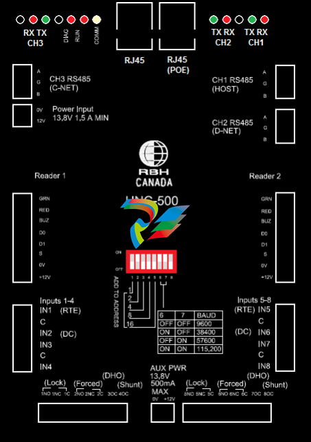
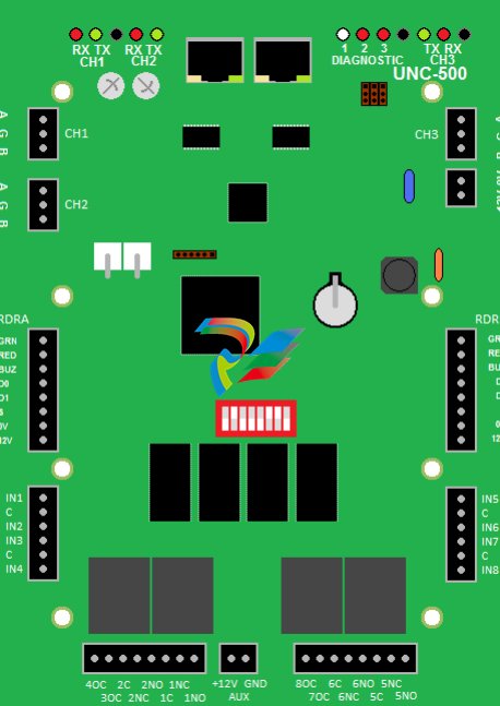
AXIOMUNC500 Silkscreen Legend
The UNC500 has been designed to take over the functionality of the Axiom NC100 (network controller),
an RC-2 (reader controller) and an LIF (local area network interface). The network interface can also
contain a POE (power over Ethernet) converter.
Communication
The UNC500 has three RS485 ports and an Ethernet 10/100 interface. Depending on the hardware
configuration all three channels may not be available. Communications from the host computer running
Axiom software can be achieved in the following ways; either via Ethernet through a socket interface or
via RS485 through a direct connection to a designated channel. The Ethernet interface may be single or
dual ported 10/100 Mbs, depending on how the board is configured. The UNC500‟s RS485 channels 1,
2, or 3 may be programmed as „HOST‟, „DNET‟, „NCNET‟, or „CNET‟. Use the DIP switch to select
baud rate for Host communications as 9600, 38400, 57600, or 115200.
Networks
There are three networks supported by the UNC500 these are:
1) Host Communications through the Ethernet or direct connection.
2) Device Communications for devices such as additional RC-2s starting at address 2, Alarm Keypads,
IOC-16 controllers, and PC100.
3) Controller Communications for controllers such as additional UNC500s or for NC100s via:
a. NCNET a protocol designed for RS485 communications between UNC500‟s only.
b. CNET for connection with NC100‟s.
Outputs
There are four form C relays and four open collector outputs that can be programmed as general purpose
or default applications. Although the contacts are rated at 12 amperes at 125vac the surge protectors
prevent voltages greater then 40vac or 56vdc from being applied. The recommended use of the relays is
to provide isolated outputs for driving electric strikes or magnetic locks at a maximum voltage of 24v.
The open collector outputs are current limited to 100 milli-amperes direct current only.
Auxiliary Power
A thermal fuse protected power output rated at 500 milli-amps 12Vdc.
Inputs
There are eight inputs used for sensor connections. Four are configured as general purpose and four are
either programmed for default application or for general purpose. The software provides configuration
information used to decode the state of the contacts. The following table illustrates the seven circuit type
assignments. Note that when an input is armed it will only report alarm or restore states. All “normal”
states are translated to “restore” and all other states are translated to “alarm”.
Reader Interface
Two standard wiegand interfaces provide the following connections for typical proximity readers:
1) Thermal fuse protected power (500ma @12vdc).
2) Wiegand data interface.
3) Reader tamper input (s). Initially if open it will be ignored but once a short is connected it will
report a reader tamper alarm whenever the input is opened.
4) LED and beeper outputs are open collector current limited to 100ma.
Battery Charger
The battery charger routes input power from the 12v input source or 15V POE module through a series
power resistor (24 Ω) and constantly monitors the battery voltage. If the battery voltage exceeds 13.8v
the battery charger turns off until the voltage has reached 12v. If the battery terminals are not connected
this could lead to a constant pulsing of the battery charger output and reporting the battery state as battery
– low, battery – normal. To prevent this from happening the battery test cycle is initiated when ten
cycles are counted. If the battery test fails the charger is turned off until a power failure is detected or a
battery is re-applied.
Reverse Battery Protection
A combination of a three ampere diode and a 1.6 amp thermal fuse protects against accidental connection
of a battery in the reverse direction.
Battery Test
A battery test cycle is operator initiated or scheduled. When initiated the charger is turned off and a
24Ω resistor provides a load to the battery for about ten seconds. If during this period the voltage drops
below 10 volts a battery alarm message is sent to the host, otherwise a battery normal message is sent.
Fuse Monitoring
Besides monitoring the battery voltage the UNC500 also monitors the input voltage (DC), auxiliary
voltage (aux) and the reader voltage (reader) and reports to the host whenever the state changes.
Diagnostic LED’s
Each RS485 circuit has a red and green LED to indicate when a signal is received or transmitted.
Diagnostic 1 is a bicolour LED when red indicates receiving data from the host and when green indicates
transmission of data.
Diagnostic 2 will flash slowly when connected to the host and quickly when not connected.
Diagnostic 3 will flash when a power problem such as a low battery or low auxiliary power is detected.
Tamper Detection
A tamper wire may be connected to JP1 located close to the power resistors on the board. A short to this
input is normal and an open is alarm.
RAM Memory
The static ram memories hold the database from the host that is downloaded using Axiom software. The
coin cell provides power to these memories as well as the real time clock.
Flash Memory
The UNC500 also has flash memory that is used for set-up parameters and firmware. Firmware may be
upgraded using two methodologies for the whole application or just the formats. To upgrade the whole
application the software will select the network controller and pass an RBH file. To upgrade just the
formats the software will select the first RC-2 device and pass a different RBH file.
The AxiomV™ access control system consists of one or more network controllers (NC-100 or UNC500).
All information required by the controller is downloaded from the PC and stored locally non-volatile
flash memory. This information includes configuration data, cardholder records, access levels,
schedules, and all other records necessary for the operation of the system. The controller operates
independent of the PC and all decision-making is performed locally, even in the event of total power loss.
The UNC500 contains a powerful 32-bit micro-controller and has either 2Mb, 4Mb, or 8Mb of RAM.
Connection Details
Power Input
The UNC500 controller requires 13.8vdc to be supplied from an external source.
CH1 RS485 (HOST)
The Host port connects the UNC500 to a PC through an RS485 interface.
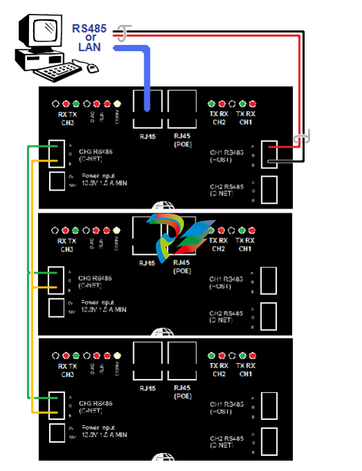
CH2 RS485 (D-NET)
The D-NET (Device Network) connects local device controllers (RC-2, IOC-16,
SafeSuite Panels, NRC2000, or NURC2000) to the UNC500 controller on a high-speed
bi-directional RS485 network. Connect CH2 on the UNC500 to CH1 on the first device
controller, and then connect it to CH1 on the next device controller on the D-NET and so
on. (see the D-NET diagram on page16)
CH3 RS485 (NCNET)
The NCNET (Controller Network) connects the UNC500 controller to other on a highspeed bi-directional RS485 network. CH3 on the master controller connects to CH3 on
the next UNC500 on the network or to CH1 on the next NC-100 controller in the
network (if the Arcnet option is added). (see NCNET diagram on page14.)
DIP Switch Settings
The UNC500 DIP switch controls the device‟s address and serial port baud rate. The
system must be powered down if the controller address is changed using DIP switches 1
through 5. DIP switch changes for a change in baud rate are processed immediately and
do not require a power down.
Note: To Reset Panel – All DIP switches must be off.
DIP Switch
DIP Switch Function
1 - 5 Controller Address
6,7 Controller Baud Rate
8 not used
Controller Addressing
Use DIP switches 1, 2, 3, 4, and 5 to select the controller address. The address is binary
coded and the switch settings for all fifteen possible addresses are given below. The
fifth DIP Switch is not usable at this time
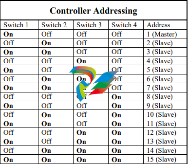
Master Controller
Each network must have a single unit designated as the master controller. The master
controller connects to the PC. Setting the DIP switch address to 1 will automatically
designate a unit as the master controller.
Slave Controller
All controllers addressed 2 through 15 are referred to as slave controllers.
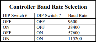
CH1 RS485 Port Baud Rate Selection (Master Only)
The controller's serial port baud rate is set with controller DIP switches 6 and 7. This
setting determines the speed used to communicate with the PC; the controller baud rate
must be the same as the baud rate set for the port within the AxiomV™ software. The
default baud rate is 9600.
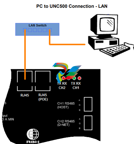
PC Connection
The master controller is connected to either a serial port on the PC or through the local
Ethernet via a static IP address. The means of communication is configured in the
AxiomV™ software under Network Properties/Port Type.
RS485 Connection
The RS485 interface allows the distance between the controller and the PC to be up to
4000 feet (1200 meters) at 38.4k baud. RS485 requires a twisted pair cable 22AWG.
Termination is built into the UNC500 and the USB-RS485 module
PC to UNC500 Connection – RS485 Wiring
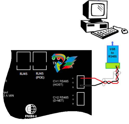
Cable Specification
Twisted pair, shielded, 18 to 22 AWG
Maximum Cable Length
4000 feet (1200 meters)
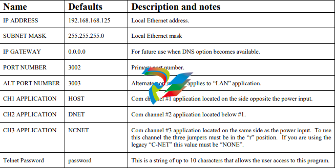
UNC500 TCP/IP Connection
The master controller in some installations may not be directly connected to the PC and
may be linked by the local Ethernet. The system supports a static IP address only
[default address is 192.168.168.125]. To change the IP address of the unit you can either
use IPLocator [a utility program provided by RBH] or Telnet.
To program the UNC500 through Telnet you first have to set all DIP switches off.
Connect to the panel with an Ethernet cable and configure your computer to have IP
address 192.168.168.20 [remember to reconfigure your machine’s IP address back
when you are done]. In the „cmd‟ window type the following „telnet 192.168.168.125‟.
If a connection is made the following message will be displayed.
Telnet Opened on port 23
2 MEG RAM detected.
A password is required in order to change user parameters. The default password is
„password‟. The password can be changed by the user. After entering the password the
following items are available for the use to alter.
CNET (Controller Network)
Up to fifteen network controllers can be linked together and feed into a single
communication port on the PC. Controller number 1 is designated the master controller
and may be connected to the PC using serial or TCP/IP communications. The remaining
controllers are referred to as slaves and can only communicate to the PC through the
master unit.
NCNET (Controller Network)
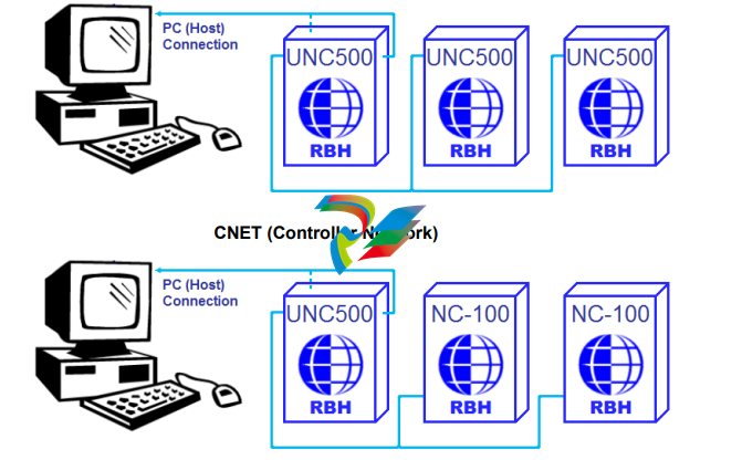
UNC500 controller can only be connected to NC-100 controller if the Arcnet option has
been added [C-Net]. To get the Arcnet to function you need to set jumpers JP5, JP6, &
JP7 to „A‟ (for Arcnet), and configure CH3 in the Telnet setup to be „none‟.
When combining UNC500s and NC100s; connect CH2 of the previous panel and CH1 of
the next panel to CH3 (C-NET) of the UNC500. Since the C-Net is a loop; the previous
panel to the first panel is the last panel, and the next panel from the last panel is the first
panel.
NCNET Cable
Use 20 to 22 AWG shielded stranded twisted pair cable for all C-NET connections.
NCNET Maximum Cable Length
The maximum distance for any link in the C-NET is 2500 feet (760 meters) and the total
length cannot exceed 10000 feet (3000 meters).
D-NET Device Network
Up to four RC-2 reader controllers, and up to sixteen IOC-16 input/output controllers,
may be connected to each network controller in the C-NET using high speed RS485
communications.
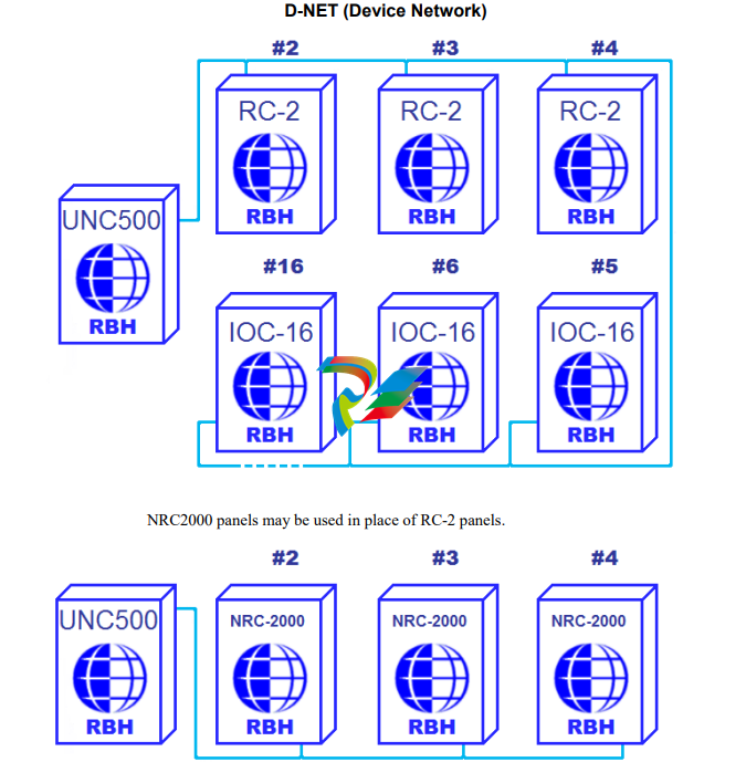
NURC2000 may also be used in place of RC-2 panels.
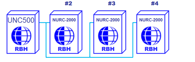
The D-NET connects IOC-16, RC-2, SafeSuite™ panels, PC-100, NRC2000, and
NURC2000 devices in a daisy chain fashion (parallel connection) to the network
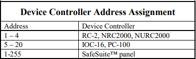
controller. Device controllers do not have to be addressed sequentially. However, using
sequential device controller addressing is recommended as this makes your cabling
diagrams easier to follow and simplifies troubleshooting as the devices are in the correct
numerical sequence.
-
 HIRSCHMANN MSM20-M2M2M2M2SY9HH9E Ethernet media modul
 -
 HIRSCHMANN SPIDER-PL-20-05T1999999TWVHHHH Industrial Ethernet Rail Switch
 -
 Hirschmann SPIDER-PL-20-07T1M2M299TWVHHHH Industrial ETHERNET Rail Switch
 -
.png) Hirschmann (Belden) RS20-1600M2M2SDAEHC09.1.00 DIN-rail managed industrial Fast Ethernet switch
Hirschmann (Belden) RS20-1600M2M2SDAEHC09.1.00 DIN-rail managed industrial Fast Ethernet switch -
 Hirschmann (Belden) RS30-1602O6O6TDAPHC09.1.00 DIN-rail managed industrial Ethernet switch
 -
 Hirschmann (Belden) RS30-2402O6T1SDAPHH09.0.13 DIN-rail industrial Ethernet switch
 -
Hirschmann (Belden) SPIDER-PL-20-04T1S29999TY9HHHH Ethernet DIN-rail switch
-
 HIRSCHMANN RS20-1600T1T1SDAUHX Switch
 -
 HIRSCHMANN BRS42-0012OOOO-SPCZ99HHSES industrial switch
 -
 Hirschmann RS20-0800S2S2TDHPHH09.0.14 Fast Ethernet DIN rail switch.
 -
 HIRSCHMANN MM20-Z6Z6M2M2SAHH Hybrid Fast Ethernet Media Module
 -
 HIRSCHMANN MM20-Z6Z6T1T1SAHH hot-swappable hybrid Fast Ethernet Media Module
 -
 HIRSCHMANN MM20-P9P9T1T1SAHH Hybrid Fast Ethernet Media Module
 -
 HIRSCHMANN MM20-M4T1T1T1SAHH Hybrid Fast Ethernet Media Module
 -
 HIRSCHMANN MM20-M4M4T1T1SAHH Hybrid Fast Ethernet Media Module
 -
 HIRSCHMANN MM20-M2M2M2M2SZHH Ethernet media module
 -
HIRSCHMANN MM20-M2M2M2M2SAHH Ethernet media module
-
 HIRSCHMANN MM20-T1T1T1T1EBH 4-port Fast Ethernet Copper Cable Media Module
 -
HIRSCHMANN MM20-T1T1T1T1SAHH 4-port Fast Ethernet Copper Cable Media Module
-
HIRSCHMANN MM20-T1T1T1T1SAHH 4-port Fast Ethernet Copper Cable Media Module
-
 HIRSCHMANN MM20-Z6Z6EBH Hot-swappable fast Ethernet media module
 -
 HIRSCHMANN MM20-Z6Z6SAHH Ethernet media module
 -
HIRSCHMANN MM20-Z6Z6Z6Z6EBH Industrial Media Module
-
 MSM40-T1T1T1TZ9HH9E99.9.99 HIRSCHMANN Switch
 -
 HIRSCHMANN MS20-0800SAAEHC / MS20-0800SAAEHC0 8-port modular Layer 2 management Ethernet switch
 -
 Hirschmann RSPM20-4T14T1SZ9HHS9 Switch RSPM20-4T14T1SZ9HHS9
 -
 HIRSCHMANN RS20-1600M2M2SDAEHH09.1. RS20/30/40 Managed Switch configurator
 -
HIRSCHMANN RS20-1600M2M2SDAEHX09.0.00 Ethernet switch
-
 HIRSCHMANN BELDEN SPIDER-PL-20-07T1M2M299TY9HHHH / SPIDERPL2007T1M2M299TY9HHHH
 -
HIRSCHMANN MM3-1FXS2/3TX1 Switching Board Module
-
 HIRSCHMANN RSPE30-24044O7T99-ECCP999HHSE2A08.1.00 Industrial-grade fanless management-type Ethernet switch
 -
 HIRSCHMANN RS30-1602OOZZSDAEHC09.1.00 DIN-rail-mounted managed Layer 2 Ethernet switch
 -
 HIRSCHMANN MACH104-20TX-F Managed 24-port Full Gigabit 19" Switch
 -
 HIRSCHMANN Switch RS20-0800M4M4SDAE
 -
Hirschmann RS30-1602O6O6SDAEHH09.1. Management-type Ethernet switch
-
 Hirschmann RS30-1602OOZZSDAEHC09.0.10 Open rack-style Ethernet switch
 -
 HIRSCHMANN RSPE30-24044O7T99-SCCV999HHSI2SXX.X.XX High-Availability Seamless Redundancy
 -
HIRSCHMANN RSPE30-24044O7T99-SCCZ999HHSE2A DIN-rail Ethernet switch
-
HIRSCHMANN MM2-4TX1-EEC switch
-
HIRSCHMANN MSM40-T1T1T1T1TZ9HH9E99.9.99 Module
-
 HIRSCHMANN RS20 Rail Switch RS20-0400S4T1SDAEHC07.1.01
 -
 HIRSCHMANN M4-FAST8-SFP Fast Ethernet media module
 -
 HIRSCHMANN RS20-0400M2T1SDAP Managed Fast-Ethernet-Switch
 -
 HIRSCHMANN BELDEN SPIDER II 8TX/1FX EEC Industrial Ethernet Rail Switch
 -
HIRSCHMANN MM3-2FXS2/2TX1
-
 HIRSCHMANN RS2-4TX/1FX EEC Industrial Ethernet Rail Switch
 -
 RS30-0802O6O6SDAEHC09.0.10 HIRSCHMANN Switch
 -
 HIRSCHMANN m4-8TP-RJ45 Ethernet Media Module
 -
 HIRSCHMANN MSP30-24040SCZ9URHHE3A switch
 -
 Hirschmann rack MS30-1602SAAPHC
 -
 HIRSCHMANN RS2-FX/FX Industrial Switch Module
 -
Rs1txfx - Hirschmann - Rs1-Tx/Fx Rail Switch
-
RS20-0800S2S2SDAEHC09.1.00 HIRSCHMANN Commutator
-
 Hirschmann EAGLE20 TX/TX Industrial Security Router
 -
 Hirschmann SPIDER-SL-20-04T1S29999SY9HHHH Industrial Switch
 -
 HIRSCHMANN MAR1040-4C4C4C4C9999SMMHRHHXX.X. Gigabit Ethernet Switch configurator
 -
 Hirschmann MAR1040 Industrial Switch
 -
 HIRSCHMANN BELDEN RS30-1602O6O6SDAE
 -
Hirschmann RS20-1600M2M2SDAUHC Ethernet DIN rail switch
-
 HIRSCHMANN OCTOPUS 24M industrial switch
 -
 HIRSCHMANN RS20-1600T1T1SDAE Management-type Ethernet switch
 -
 HIRSCHMANN RS20-1600T1T1SDAUHH industrial switch
 -
HIRSCHMANN RS20-0800M2M2SDAPHC09.0.04 switch
-
 Hirschmann MR 8-03 24V DC Industrial Modular Bridge/Router
 -
 HIRSCHMANN RS20-0400M2T1SDAPHC08.0.01 Managed Switch
 -
 MACH1130 Hirschmann Industrial Switch
 -
 HIRSCHMANN 943824-002 SPIDER 5TX Industrial Ethernet Switch
 -
 HIRSCHMANN RS30-0802O6O6SDAEHC09.1.00 Managed Industrial Switch
 -
 HIRSCHMANN RS20-0400M2M2TDAEHC04.0.01 Industrial Switch
 -
 HIRSCHMANN BRS20-0600Z6Z6-STCZ99HHSES Industrial Switch
 -
 HIRSCHMANN MACH104-20TX-FR-L3P Industrial Ethernet Switch
 -
 HIRSCHMANN RS40-0009CCCCEDBPHH06.0.01 Industrial Switch
 -
 HIRSCHMANN RS2-3TX/2FX EEC Industrial Ethernet Switch
 -
 Hirschmann MACH 1020/1030 Fast/Gigabit Rack Mount Switches
 -
HIRSCHMANN RS20-0800M2M2SDAPHC09.0.14 Industrial Switch
-
 HIRSCHMANN RS20-1600T1T1SDAEHC09.0.04 Industrial Switch
 -
 HIRSCHMANN RSB20-0800T1T1EAABHH Industrial Switch
 -
 HIRSCHMANN MACH4002-48+4G-L3E Industrial Backbone Switch
 -
 HIRSCHMANN RS20-0400S2T1SDAE Industrial Managed Switch
 -
HIRSCHMANN RS20-0800S2T1SDAUHC Industrial Switch
-
 HIRSCHMANN RS20-2400S4S4SDAEHC09.0.14 industrial switch
 -
 HIRSCHMANN OS20-001200T5T5T5- TBBZ999HHNE3S 08.1.00 industrial switch
 -
HIRSCHMANN OS20-001200T5T5T5- TBBZ999HHNE3S 08.1.00 industrial switch
-
 HIRSCHMANN RS40-0009CCCCSDAEHH09.0.14 switch
 -
 Hirschmann RS20-1600T1T1SDAUHC Management-type Ethernet Switch
 -
 Hirschmann M1-8SFP Switche
 -
Hirschmann Industrial Ethernet Ruggedized Switch MACH1000 Family
-
 Basler Electric, Solid State Protective Relay, BE1-60
 -
BASLER ELECTRIC SR4A-2B15B3A Static Voltage Regulator
-
.png) BASLER ELECTRIC EXCITER DIODE MONITOR EDM-200
BASLER ELECTRIC EXCITER DIODE MONITOR EDM-200 -
.png) BASLER ELECTRIC DECS125-15-B2C5 DIGITAL EXCITATION CONTROL SYSTEM V 2.0.9
BASLER ELECTRIC DECS125-15-B2C5 DIGITAL EXCITATION CONTROL SYSTEM V 2.0.9 -
 BASLER ELECTRIC BE1-851 OVERCURRENT PROTECTION RELAY MECHANISM
 -
 Basler Electric BE1-51A / BE151A
 -
 Basler Electric BE1-40Q Loss of Excitation Relay
 -
 Basler Electric BE1-87G Variable Percentage Differential Relay
 -
 Basler Electric BE1-11 Protection System I5A3M2P2N0EA00
 -
 BASLER ELECTRIC DECS-200-1C Digital Excitation Control System
 -
 Basler Electric / Kohler BE1-11g Generator Protection Relay G5A3M2J2N0E000
 -
BASLER ELECTRIC DECS125-15 DIGITAL EXCITATION CONTROL SYSTEM
-
 BASLER ELECTRIC BE1-951 OverCurrent Protecton System
 -
Basler Electric DECS-200-1L Digital Excitation Control System
-
 Basler Electric DGC-2020HD-5NS1DNSBA Digital Genset Controller -
 -
 BASLER ELECTRIC BE1-81T1EE1WA0N1F / BE181T1EE1WA0N1F
 -
 BASLER ELECTRIC BE1-25M1EA6PN5R1F / BE125M1EA6PN5R1F
 -
 BASLER ELECTRIC DECS-250-LN1SN1N DIGITAL EXCITATION CONTROL SYSTEM
 -
Basler Electric DECS-250-CN2CN 1N Digital Excitation Control System Unit
-
 BASLER ELECTRIC DECS-300-C0N0 DIGITAL EXCITATION CONTROL SYSTEM
 -
 BASLER ELECTRIC BE1-87T-A1E-A1J-D0S1F / BE187TA1EA1JD0S1F
 -
BASLER ELECTRIC BE1-11-G6D1M0J2P0E000 Protection System
-
 BASLER ELECTRIC BE1-GPS100-E4N1H1N GENERATOR PROTECTION SYSTEM
 -
 Jaquet Relay card (Auxiliary module) FTV 3090 377Z-03985
 -
 Jaquet Trip Chain Control card FTBU 3034 377Z-05030
 -
 Jaquet with input card -E04 FTFU 3024 -E04 377Z-05855
 -
 Jaquet with input card -E03 FTFU 3024- E03 377Z-03983
 -
 Jaquet FTFU 3024- E02 377Z-03982 with input card -E02
 -
 Jaquet FTFU 3024-E01 377Z-03981 with input card -E01
 -
 Hirschmann RS20-2400T1T1SDAE Industrial Managed Ethernet Switch
 -
 Hirschmann BELDEN EAGLE30-04022O6TT999SCCV9HSE3F
 -
 Hirschmann MM3-2FXS2/2TX MICE Media Module
 -
 Hirschmann RS20-1600M2M2SDAPHC08.0.05 Industrial Managed Switch
 -
 Hirschmann OZD Profi 12M G12-1300 PRO Fieldbus Repeater
 -
Hirschmann SPIDER 4TX/1FX-ST EEC Industrial Ethernet Switch
-
 Hirschmann MM2-2FXM3/2TX1 MICE Media Module
 -
 Hirschmann RS20-2400M2M2SDAPHC09.0.14 Industrial Switch
 -
 Hirschmann RS20-0400M2M2SDAEHC07.1.05 OpenRail Switch
 -
 Hirschmann OZD Profi 12M G12-EEC Fieldbus Repeater
 -
HIRSCHMANN MDA422-1/2-3.5c-23/46 sensor
-
Hirschmann RS30-2402T1T1SDAUHC Managed Industrial Switch


