
GEDatasheet MVME6100 Series VME Single-Board Computer
The promise of the VME Renaissance is innovation, performance and investment
protection. The MVME6100 series from Motorola delivers on this promise. The
innovative design of the MVME6100 provides a high performance platform that allows
customers to leverage their investment in their VME infrastructure.
Customers looking for a "technology refresh" for their application, while maintaining
backwards compatibility with their existing VMEbus infrastructure, can upgrade to the
MVME6100 series and take advantage of its enhanced performance features.
The MVME6100 series is designed to meet the needs of OEMs servicing the defense
and aerospace, industrial automation and medical imaging market segments.
■ 2eSST VMEbus protocol with 320MB/s transfer rate
across the VMEbus
■ Migration path from existing Motorola VMEbus
platforms
■ High-performance MPC7457 PowerPC® processor
running at 1.267 GHz, ideal for data-intensive
applications
■ 128-bit AltiVec™ coprocessor for parallel processing
■ Up to 1GB of on-board DDR ECC memory
■ Two 33/66/100 MHz PMC-X sites allow the addition
of industry-standard, application-specific modules
■ Dual Gigabit Ethernet interfaces
■ 128MB of Flash memory in two 64MB banks
VMEbus 2eSST Performance
The MVME6100 series is the first VMEbus single-board computer (SBC) designed with the Tundra Tsi148™ VMEbus
interface chip offering 2eSST VMEbus performance. The 2eSST (two edge source synchronous transfer) protocol
causes the VMEbus to run at a practical bandwidth of 320MB/s in most cases. The 2eSST protocol has existed for
some time (the draft standard for trial use was published in 1999 and released as an ANSI standard in 2003), but
until now, 2eSST boards would not work in a standard VMEbus backplane because the existing VMEbus transceivers
could not support the required VMEbus 2eSST signaling speeds. Texas Instruments has developed new VMEbus
transceivers that support the VMEbus signal switching speeds required by the 2eSST protocol. The combination of
the new Texas Instruments VMEbus transceivers and the Tsi148 VMEbus legacy protocol support allows customers
to integrate the MVME6100 series into their existing infrastructure providing backward compatibility and thereby
preserving their investment in existing VMEbus boards, backplanes, chassis and software.
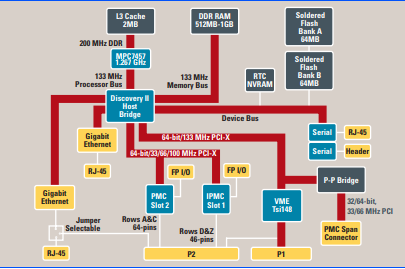
Balanced Performance
The MVME6100 series provides more than just faster VMEbus transfer rates; it provides balanced performance from
the processor, memory subsystem, local buses and I/O subsystems. The processor running at speeds of 1.267 GHz is
ideal for data-intensive applications. The state-of-the-art host bridge, with support for a 133 MHz host bus and a 133
MHz DDR memory bus, is well matched to the processor. To ensure that the MVME6100 series can handle the
320MB/s data rates of 2eSST, the Tsi148 VMEbus interface chip is connected to one of the 133 MHz PCI-X buses on
the host bridge. The second PCI-X bus has dual PMC-X sites—each site supports PMC or PMC-X cards supporting
PCI bus speeds from 33 to 100 MHz. The MVME6100 also offers dual Gigabit Ethernet interfaces. All of this adds up
to a set of well-balanced, high-performance subsystems for unparalleled performance.
Application Benefits Defense and Aerospace
In the defense and aerospace market segment, the MVME6100 series is well suited for command and control
applications that utilize commercial grade products such as naval sheltered systems, stationary ground systems, and
reconnaissance aircraft systems. The MVME6100 series helps to provide more performance for these applications
than previous VME solutions have been able to supply by using the 1.267 GHz processor. This combined with dual
PCI-X buses capable of 100 MHz speed for PMC modules and an 8x increase in the VME bandwidth eliminates many
of the bottlenecks faced by command and control solutions today. These applications can now take advantage of the
latest PowerPC processors in a dense computing configuration without the difficulties of trying to cool
multiprocessor boards and managing I/O and VME bottlenecks. With the addition of Motorola’s processor PMCs
(PrPMCs), additional PowerPC architecture-compatible processors can be added for a multiprocessor solution
without sacrificing any of the MVME6100 series benefits.
Industrial Automation
The MVME6100 is also ideally suited for semiconductor process equipment (SPE), automated test equipment (ATE)
and a variety of other high-end industrial automation applications because of its increased bus bandwidth and faster
processing speeds. The backwards compatibility of the MVME6100 series with existing VME products helps to
provide OEMs a way to extend the life and capability of their current designs without sacrificing existing key
hardware and software investments. The DSP-like AltiVec technology, which is incorporated into the processor,
allows the MVME6100 series to be used for an assortment of vector processing applications. And with two PMC
sites, the MVME6100 series can be customized.
Medical Imaging
Medical imaging applications such as Nuclear Medicine (NM), Positron Emission Tomography (PET), Magnetic
Resonance Imaging (MRI), X-Ray and Computed Tomography (CT) that entail intensive image processing,
manipulation and algorithm-intensive computations can benefit from the 2eSST protocol’s 8x increase in VMEbus
transfer rates. With the ability of the MVME6100 series to work with existing VMEbus backplanes and boards, OEMs
can increase their overall system performance while protecting their software and hardware investments. The
performance of the MVME6100 series also helps OEMs to reduce the overall number of embedded cards required in
a medical imaging application so that space issues become less of a factor.
Backwards Compatibility The MVME6100 series continues the direction of providing a migration path from Motorola’s embedded controllers
such as the MVME2300/MVME2400 and from Motorola’s SBCs such as the MVME2600/2700 to a single platform.
The MVME6100 series, like the MVME5100 and MVME5500 series, merged the best features of Motorola’s
embedded controllers and SBCs enabling OEMs to support varying I/O requirements with the same base platform,
simplifying part number maintenance, technical expertise requirements and sparing.
The MVME6100 series offers customers a migration path from the MVME2300, MVME2400, MVME2600,
MVME2700, MVME5100 and MVME5500 boards to allow them to take advantage of features such as the MPC7457
processor, DDR memory, Gigabit Ethernet, PCI-X and 2eSST.
PCI Expansion
The MVME6100 has a 32/64-bit, 33/66MHz PCI connection to support PCI expansion carriers such as the Motorola
PMCspan.
P2 I/O Modes
Like the MVME5100 and MVME5500 series, the MVME6100 series supports two, jumper-configurable P2 I/O modes:
the PMC mode and IPMC mode. PMC mode is backwards compatible with the MVME2300/MVME2400 and
MVME5100/MVME5500 in PMC mode. In PMC mode, 64 pins from PMC slot 1 and 46 pins from PMC slot 2 are
available on P2 for PMC rear I/O. In IPMC mode, the MVME6100 series supports legacy MVME761 or MVME712M
I/O modules (with limited PMC I/O) when an IPMC761 or IPMC712 PMC card is populated in PMC slot 1. In this
configuration, PMC slot 2 contains some signals that are reserved for extended SCSI.
IPMC Modules
The IPMC761 and IPMC712 are optional add-on PMC modules that provide backwards compatibility with previousgeneration Motorola products (such as MVME2600/MVME2700 and MVME5100/MVME5500 in IPMC mode) using
the MVME761 or MVME712M transition module. IPMC modules provide rear I/O support for:
• One single-ended Ultra Wide SCSI port
• One parallel port
• Four serial ports (two or three async and one or two sync/async, depending on module)
With this PMC card configuration, one PMC slot is still available to provide support for OEM product customization.
Transition Modules
MVME761
The MVME761 transition module provides industry-standard connector access to the IEEE 1284 parallel port, a
10/100BaseTX port via an RJ-45 connector, two DB-9 connectors providing access to the asynchronous serial ports
configured as EIA-574 DTE and two HD-26 connectors providing access to the sync/async serial ports. These serial
ports, labeled as Serial 3 and Serial 4 on the faceplate of the MVME761, are individually user-configurable as
EIA-232, EIA-530, V.35, or X.21 DCE or DTE via the installation of Motorola serial interface modules (SIMs).
A P2 adapter provides interface module signals to the MVME761 transition module. The 3-row P2 adapter can be
used for 8-bit SCSI. A 5-row P2 adapter supports 16-bit SCSI and PMC I/O.
MVME712M
The MVME712M transition module provides industry-standard connector access to the parallel port, a narrow SCSI
port and four DB-25 connectors providing access to the asynchronous/synchronous serial ports jumper configurable
as EIA-232 DCE or DTE. A P2 adapter provides interface signals to the MVME712M transition module. The 3-row P2
adapter can be used for 8-bit SCSI.
To gain access to the additional user-definable I/O pins provided via the 5-row VME64 extension connector, a special
P2 adapter board is available. This adapter panel replaces the traditional 3-row P2 adapter and extends its capability
by providing access to the PMC I/O pins.
Software Support Firmware Monitor
The MVME6100 firmware (known as MOTLoad) is resident in the MVME6100 Flash and provides power-on self-test
(POST), initialization and operating system booting capabilities. In addition, it provides a debugger interface similar
to the time proven “Bug” interface on previous VMEbus boards from Motorola.
Operating Systems and Kernels
The MVME6100 series supports booting a variety of operating systems including a complete range of real-time
operating systems and kernels. A VxWorks board support package and Linux support will be available for the
MVME6100 series
Processor
System Controller
Marvell MV64360
Main Memory
Flash Memory
NVRAM
VMEbus Interface
SPECIFICATIONS
Microprocessor: MPC7457
Clock Frequency: 1.267 GHz
On-chip L1 Cache (I/D): 32K/32K
On-chip L2 Cache: 512K
L3 Cache: 2MB
Type: Double data rate (DDR) ECC SDRAM
Speed: DDR266 (133 MHz)
Capacity: Up to 2GB, all memory on board
Configurations: Two banks, 512MB or 1GB configurations
available at release
Type: EEPROM, on-board programmable
Capacity: 128MB soldered Flash in two banks of
64MB each
Write Protection: Flash is write protectable via jumper
Capacity: 32KB (4KB available for users)
Cell Storage Life: 50 years at 55° C
Cell Capacity Life: 5 years at 100% duty cycle, 25° C
Removable Battery: Yes
Compliance: ANSI/VITA 1-1994 VME64 (IEEE STD
1014), ANSI/VITA 1.1-1997 VME64
Extensions, VITA 1.5-199x 2eSST
Controller: Tundra Tsi148
DTB Master: A16, A24, A32, A64; D08-D64, SCT, BLT,
MBLT, 2eVME, 2eSST
DTB Slave: A16, A24, A32, A64; D08-D64, SCT, BLT,
MBLT, 2eVME, 2eSST, UAT
Arbiter: RR/PRI
Interrupt
Handler/Generator:
IRQ 1-7/Any one of seven IRQs
System Controller: Yes, jumperable or auto detect
Location Monitor: Two, LMA32
Ethernet Interface
Asynchronous Serial Ports
Dual IEEE P1386.1 PCI Mezzanine Card Slots
PCI Expansion Connector
Counters/Timers
Board Size and Weight
Power Requirements
Mean Time Between Failure
178,403 hours, calculated using Bellcore Standard: Issue 6, Method 1,
Case 3
IPMC Modules PMC Interface
SCSI Bus
Note: 16-bit SCSI operation precludes the use of some PMC slot 2
signals.
Asynchronous Serial Ports
Synchronous Serial Ports
Controller: Ethernet controller integrated into host
bridge; two Gigabit Ethernet interfaces
Interface Speed: 10/100/1000Mb/s
Connector: One routed to front panel RJ-45; one
routed to front panel RJ-45 or optionally
routed to P2 (10/100 routed to RJ-45 on
MVME761 for IPMC mode, Gigabit routed
to P2 for PMC mode)
Controller: ST16C554DCQ64
Number of Ports: Two, 16550 compatible
Configuration: EIA-574 DTE
Async Baud Rate, b/s
max.:
38.4K EIA-232, 115Kb/s raw
Connector: One routed to front panel RJ-45; one on
planar for development use
Address/Data: A32/D32/D64, PMC PN1, PN2, PN3, PN4
connectors
PCI Bus Clock: 33 MHz, 66 MHz or 100 MHz
Signaling: 3.3V, 5V tolerant
Power: +3.3V, +5V, ±12V
Module Types: Two single-wide or one double-wide, front
panel or P2 I/O, PMC and PrPMC support
Address/Data: A32/D32/D64
PCI Bus Clock: 33/66 MHz
Signaling: 5V
Power: +3.3V, +5V, ±12V
Connector: 114-pin connector located on MVME6100
planar, same location as on MVME5500
planar
TOD Clock Device: ST (SGS-Thompson) M4T28
Real-Time
Timers/Counters:
Four, 32-bit programmable
Watchdog Timer: Time-out generates reset
Height: 233.4 mm (9.2 in.)
Depth: 160.0 mm (6.3 in.)
Front Panel Height: 261.8 mm (10.3 in.)
Width: 19.8 mm (0.8 in.)
Max. Component
Height:
14.8 mm (0.58 in.)
Weight: 425 g/15 oz. (Scanbe handles); 468 g/16.5
oz. (IEEE handles)
(Not including power required by PMC or IPMC modules)
+5V ± 5%
MVME6100: 8.4 A typ., 10.2 A max.
MVME6100 with
MVME761:
9.2 A typ., 11.2 A max.
Address/Data: A32/D32/D64, PMC PN1, PN2, PN3, PN4
connectors
PCI Bus Clock: 33 MHz
Signaling: 5V
Module Type: Basic, single-wide; P2 I/O
Controller: Symbios 53C895A
PCI Local Bus DMA: Yes, with PCI local bus burst
Asynchronous (8-bit
mode):
5.0MB/s
Ultra SCSI: 20.0MB/s (8-bit mode), 40.0MB/s (16-bit
mode)
Controller: 16C550 UART; 85230/8536
Number of Ports: Two (IPMC761); three (IPMC712)
Configuration: EIA-574 DTE (IPMC761);
EIA-232 (IPMC712)
Async Baud Rate, b/s
max.:
38.4K EIA-232, 115Kb/s raw
Controller: 85230/8536
Number of Ports: Two (IPMC761); one (IPMC712)
Configuration: IPMC761: TTL to P2 (both ports), SIM
configurable on MVME761;
IPMC712: EIA-232 to P2
Baud Rate, bps max.: 2.5MB sync, 38.4KB async
Oscillator Clock Rate
(PCLK):
10 MHz/5 MHz
Parallel Port Power Requirements
(Additional power load placed on MVME6100 with IPMC installed)
Transition Modules I/O Connectors
Board Size
All Modules Environmental Safety
All printed wiring boards (PWBs) are manufactured with a flammability
rating of 94V-0 by UL recognized manufacturers.
Electromagnetic Compatibility (EMC)
Intended for use in systems meeting the following regulations:
Motorola Computer Group board products are tested in a
representative system to the following standards, results pending:
Controller: PC97307
Configuration: 8-bit bi-directional, full IEEE 1284 support;
Centronics compatible (minus EPP and
ECP on MVME712M)
Modes: Master only
IPMC761 IPMC712
+5V: 0.5 A max. 0.5 A max.
+3.3V: 0.75 A max. 0.75 A max.
MVME761 MVME712M
Asynchronous Serial Ports: Two, DB-9 labeled as COM1 and COM2 Three, DB-25 labeled as Serial 1, Serial 2 and Serial 3
Synchronous Serial Ports: Two, HD-26 labeled as Serial 3 and Serial 4 (userconfigurable via installation of SIMs);
two 60-pin connectors on MVME761 planar for
installation of two SIMs
One, DB-25 labeled as Serial 4
Parallel Port: HD-36, Centronics compatible D-36, Centronics compatible
Ethernet: 10BaseT or 100BaseTX, RJ-45 Not available
SCSI: 8- or 16-bit, 50- or 68-pin connector via P2 adapter 8-bit, standard SCSI D-50
Height: 233.4 mm (9.2 in.)
Depth: 80.0 mm (3.1 in.)
Front Panel Height: 261.8 mm (10.3 in.)
Front Panel Width: MVME761: 19.8 mm (0.8 in.)
MVME712M: 39.6 mm (1.6 in.)
Operating Non-operating
Temperature: 0° C to +55° C
(inlet air temp.
w/forced air cooling)
–40° C to +85° C
Humidity (NC): 5% to 90% 5% to 90%
Vibration: 2 Gs RMS,
20-2000 Hz random
6 Gs RMS,
20-2000 Hz random
U.S.: FCC Part 15, Subpart B, Class A (non-residential)
Canada: ICES-003, Class A (non-residential)
CE Mark per European EMC Directive 89/336/EEC with
Amendments; Emissions: EN55022 Class B; Immunity: EN55024
Part Number Description
MVME6100-0161 1.267 GHz MPC7457 processor, 512MB DDR memory, 128MB Flash, Scanbe handles
MVME6100-0163 1.267 GHz MPC7457 processor, 512MB DDR memory, 128MB Flash, IEEE handles
MVME6100-0171 1.267 GHz MPC7457 processor, 1GB DDR memory, 128MB Flash, Scanbe handles
MVME6100-0173 1.267 GHz MPC7457 processor, 1GB DDR memory, 128MB Flash, IEEE handles
Related Products
PMCSPAN2-002 Primary PMCSPAN with IEEE ejector handles
PMCSPAN2-010 Secondary PMCSPAN with IEEE ejector handles
PMCSPAN1-002 Primary PMCSPAN with SCANBE ejector handles
PMCSPAN1-010 Secondary PMCSPAN with SCANBE ejector handles
Documentation is available for online viewing at http://www.motorola.com/computer/literature
-
 HIRSCHMANN MSM20-M2M2M2M2SY9HH9E Ethernet media modul
 -
 HIRSCHMANN SPIDER-PL-20-05T1999999TWVHHHH Industrial Ethernet Rail Switch
 -
 Hirschmann SPIDER-PL-20-07T1M2M299TWVHHHH Industrial ETHERNET Rail Switch
 -
.png) Hirschmann (Belden) RS20-1600M2M2SDAEHC09.1.00 DIN-rail managed industrial Fast Ethernet switch
Hirschmann (Belden) RS20-1600M2M2SDAEHC09.1.00 DIN-rail managed industrial Fast Ethernet switch -
 Hirschmann (Belden) RS30-1602O6O6TDAPHC09.1.00 DIN-rail managed industrial Ethernet switch
 -
 Hirschmann (Belden) RS30-2402O6T1SDAPHH09.0.13 DIN-rail industrial Ethernet switch
 -
Hirschmann (Belden) SPIDER-PL-20-04T1S29999TY9HHHH Ethernet DIN-rail switch
-
 HIRSCHMANN RS20-1600T1T1SDAUHX Switch
 -
 HIRSCHMANN BRS42-0012OOOO-SPCZ99HHSES industrial switch
 -
 Hirschmann RS20-0800S2S2TDHPHH09.0.14 Fast Ethernet DIN rail switch.
 -
 HIRSCHMANN MM20-Z6Z6M2M2SAHH Hybrid Fast Ethernet Media Module
 -
 HIRSCHMANN MM20-Z6Z6T1T1SAHH hot-swappable hybrid Fast Ethernet Media Module
 -
 HIRSCHMANN MM20-P9P9T1T1SAHH Hybrid Fast Ethernet Media Module
 -
 HIRSCHMANN MM20-M4T1T1T1SAHH Hybrid Fast Ethernet Media Module
 -
 HIRSCHMANN MM20-M4M4T1T1SAHH Hybrid Fast Ethernet Media Module
 -
 HIRSCHMANN MM20-M2M2M2M2SZHH Ethernet media module
 -
HIRSCHMANN MM20-M2M2M2M2SAHH Ethernet media module
-
 HIRSCHMANN MM20-T1T1T1T1EBH 4-port Fast Ethernet Copper Cable Media Module
 -
HIRSCHMANN MM20-T1T1T1T1SAHH 4-port Fast Ethernet Copper Cable Media Module
-
HIRSCHMANN MM20-T1T1T1T1SAHH 4-port Fast Ethernet Copper Cable Media Module
-
 HIRSCHMANN MM20-Z6Z6EBH Hot-swappable fast Ethernet media module
 -
 HIRSCHMANN MM20-Z6Z6SAHH Ethernet media module
 -
HIRSCHMANN MM20-Z6Z6Z6Z6EBH Industrial Media Module
-
 MSM40-T1T1T1TZ9HH9E99.9.99 HIRSCHMANN Switch
 -
 HIRSCHMANN MS20-0800SAAEHC / MS20-0800SAAEHC0 8-port modular Layer 2 management Ethernet switch
 -
 Hirschmann RSPM20-4T14T1SZ9HHS9 Switch RSPM20-4T14T1SZ9HHS9
 -
 HIRSCHMANN RS20-1600M2M2SDAEHH09.1. RS20/30/40 Managed Switch configurator
 -
HIRSCHMANN RS20-1600M2M2SDAEHX09.0.00 Ethernet switch
-
 HIRSCHMANN BELDEN SPIDER-PL-20-07T1M2M299TY9HHHH / SPIDERPL2007T1M2M299TY9HHHH
 -
HIRSCHMANN MM3-1FXS2/3TX1 Switching Board Module
-
 HIRSCHMANN RSPE30-24044O7T99-ECCP999HHSE2A08.1.00 Industrial-grade fanless management-type Ethernet switch
 -
 HIRSCHMANN RS30-1602OOZZSDAEHC09.1.00 DIN-rail-mounted managed Layer 2 Ethernet switch
 -
 HIRSCHMANN MACH104-20TX-F Managed 24-port Full Gigabit 19" Switch
 -
 HIRSCHMANN Switch RS20-0800M4M4SDAE
 -
Hirschmann RS30-1602O6O6SDAEHH09.1. Management-type Ethernet switch
-
 Hirschmann RS30-1602OOZZSDAEHC09.0.10 Open rack-style Ethernet switch
 -
 HIRSCHMANN RSPE30-24044O7T99-SCCV999HHSI2SXX.X.XX High-Availability Seamless Redundancy
 -
HIRSCHMANN RSPE30-24044O7T99-SCCZ999HHSE2A DIN-rail Ethernet switch
-
HIRSCHMANN MM2-4TX1-EEC switch
-
HIRSCHMANN MSM40-T1T1T1T1TZ9HH9E99.9.99 Module
-
 HIRSCHMANN RS20 Rail Switch RS20-0400S4T1SDAEHC07.1.01
 -
 HIRSCHMANN M4-FAST8-SFP Fast Ethernet media module
 -
 HIRSCHMANN RS20-0400M2T1SDAP Managed Fast-Ethernet-Switch
 -
 HIRSCHMANN BELDEN SPIDER II 8TX/1FX EEC Industrial Ethernet Rail Switch
 -
HIRSCHMANN MM3-2FXS2/2TX1
-
 HIRSCHMANN RS2-4TX/1FX EEC Industrial Ethernet Rail Switch
 -
 RS30-0802O6O6SDAEHC09.0.10 HIRSCHMANN Switch
 -
 HIRSCHMANN m4-8TP-RJ45 Ethernet Media Module
 -
 HIRSCHMANN MSP30-24040SCZ9URHHE3A switch
 -
 Hirschmann rack MS30-1602SAAPHC
 -
 HIRSCHMANN RS2-FX/FX Industrial Switch Module
 -
Rs1txfx - Hirschmann - Rs1-Tx/Fx Rail Switch
-
RS20-0800S2S2SDAEHC09.1.00 HIRSCHMANN Commutator
-
 Hirschmann EAGLE20 TX/TX Industrial Security Router
 -
 Hirschmann SPIDER-SL-20-04T1S29999SY9HHHH Industrial Switch
 -
 HIRSCHMANN MAR1040-4C4C4C4C9999SMMHRHHXX.X. Gigabit Ethernet Switch configurator
 -
 Hirschmann MAR1040 Industrial Switch
 -
 HIRSCHMANN BELDEN RS30-1602O6O6SDAE
 -
Hirschmann RS20-1600M2M2SDAUHC Ethernet DIN rail switch
-
 HIRSCHMANN OCTOPUS 24M industrial switch
 -
 HIRSCHMANN RS20-1600T1T1SDAE Management-type Ethernet switch
 -
 HIRSCHMANN RS20-1600T1T1SDAUHH industrial switch
 -
HIRSCHMANN RS20-0800M2M2SDAPHC09.0.04 switch
-
 Hirschmann MR 8-03 24V DC Industrial Modular Bridge/Router
 -
 HIRSCHMANN RS20-0400M2T1SDAPHC08.0.01 Managed Switch
 -
 MACH1130 Hirschmann Industrial Switch
 -
 HIRSCHMANN 943824-002 SPIDER 5TX Industrial Ethernet Switch
 -
 HIRSCHMANN RS30-0802O6O6SDAEHC09.1.00 Managed Industrial Switch
 -
 HIRSCHMANN RS20-0400M2M2TDAEHC04.0.01 Industrial Switch
 -
 HIRSCHMANN BRS20-0600Z6Z6-STCZ99HHSES Industrial Switch
 -
 HIRSCHMANN MACH104-20TX-FR-L3P Industrial Ethernet Switch
 -
 HIRSCHMANN RS40-0009CCCCEDBPHH06.0.01 Industrial Switch
 -
 HIRSCHMANN RS2-3TX/2FX EEC Industrial Ethernet Switch
 -
 Hirschmann MACH 1020/1030 Fast/Gigabit Rack Mount Switches
 -
HIRSCHMANN RS20-0800M2M2SDAPHC09.0.14 Industrial Switch
-
 HIRSCHMANN RS20-1600T1T1SDAEHC09.0.04 Industrial Switch
 -
 HIRSCHMANN RSB20-0800T1T1EAABHH Industrial Switch
 -
 HIRSCHMANN MACH4002-48+4G-L3E Industrial Backbone Switch
 -
 HIRSCHMANN RS20-0400S2T1SDAE Industrial Managed Switch
 -
HIRSCHMANN RS20-0800S2T1SDAUHC Industrial Switch
-
 HIRSCHMANN RS20-2400S4S4SDAEHC09.0.14 industrial switch
 -
 HIRSCHMANN OS20-001200T5T5T5- TBBZ999HHNE3S 08.1.00 industrial switch
 -
HIRSCHMANN OS20-001200T5T5T5- TBBZ999HHNE3S 08.1.00 industrial switch
-
 HIRSCHMANN RS40-0009CCCCSDAEHH09.0.14 switch
 -
 Hirschmann RS20-1600T1T1SDAUHC Management-type Ethernet Switch
 -
 Hirschmann M1-8SFP Switche
 -
Hirschmann Industrial Ethernet Ruggedized Switch MACH1000 Family
-
 Basler Electric, Solid State Protective Relay, BE1-60
 -
BASLER ELECTRIC SR4A-2B15B3A Static Voltage Regulator
-
.png) BASLER ELECTRIC EXCITER DIODE MONITOR EDM-200
BASLER ELECTRIC EXCITER DIODE MONITOR EDM-200 -
.png) BASLER ELECTRIC DECS125-15-B2C5 DIGITAL EXCITATION CONTROL SYSTEM V 2.0.9
BASLER ELECTRIC DECS125-15-B2C5 DIGITAL EXCITATION CONTROL SYSTEM V 2.0.9 -
 BASLER ELECTRIC BE1-851 OVERCURRENT PROTECTION RELAY MECHANISM
 -
 Basler Electric BE1-51A / BE151A
 -
 Basler Electric BE1-40Q Loss of Excitation Relay
 -
 Basler Electric BE1-87G Variable Percentage Differential Relay
 -
 Basler Electric BE1-11 Protection System I5A3M2P2N0EA00
 -
 BASLER ELECTRIC DECS-200-1C Digital Excitation Control System
 -
 Basler Electric / Kohler BE1-11g Generator Protection Relay G5A3M2J2N0E000
 -
BASLER ELECTRIC DECS125-15 DIGITAL EXCITATION CONTROL SYSTEM
-
 BASLER ELECTRIC BE1-951 OverCurrent Protecton System
 -
Basler Electric DECS-200-1L Digital Excitation Control System
-
 Basler Electric DGC-2020HD-5NS1DNSBA Digital Genset Controller -
 -
 BASLER ELECTRIC BE1-81T1EE1WA0N1F / BE181T1EE1WA0N1F
 -
 BASLER ELECTRIC BE1-25M1EA6PN5R1F / BE125M1EA6PN5R1F
 -
 BASLER ELECTRIC DECS-250-LN1SN1N DIGITAL EXCITATION CONTROL SYSTEM
 -
Basler Electric DECS-250-CN2CN 1N Digital Excitation Control System Unit
-
 BASLER ELECTRIC DECS-300-C0N0 DIGITAL EXCITATION CONTROL SYSTEM
 -
 BASLER ELECTRIC BE1-87T-A1E-A1J-D0S1F / BE187TA1EA1JD0S1F
 -
BASLER ELECTRIC BE1-11-G6D1M0J2P0E000 Protection System
-
 BASLER ELECTRIC BE1-GPS100-E4N1H1N GENERATOR PROTECTION SYSTEM
 -
 Jaquet Relay card (Auxiliary module) FTV 3090 377Z-03985
 -
 Jaquet Trip Chain Control card FTBU 3034 377Z-05030
 -
 Jaquet with input card -E04 FTFU 3024 -E04 377Z-05855
 -
 Jaquet with input card -E03 FTFU 3024- E03 377Z-03983
 -
 Jaquet FTFU 3024- E02 377Z-03982 with input card -E02
 -
 Jaquet FTFU 3024-E01 377Z-03981 with input card -E01
 -
 Hirschmann RS20-2400T1T1SDAE Industrial Managed Ethernet Switch
 -
 Hirschmann BELDEN EAGLE30-04022O6TT999SCCV9HSE3F
 -
 Hirschmann MM3-2FXS2/2TX MICE Media Module
 -
 Hirschmann RS20-1600M2M2SDAPHC08.0.05 Industrial Managed Switch
 -
 Hirschmann OZD Profi 12M G12-1300 PRO Fieldbus Repeater
 -
Hirschmann SPIDER 4TX/1FX-ST EEC Industrial Ethernet Switch
-
 Hirschmann MM2-2FXM3/2TX1 MICE Media Module
 -
 Hirschmann RS20-2400M2M2SDAPHC09.0.14 Industrial Switch
 -
 Hirschmann RS20-0400M2M2SDAEHC07.1.05 OpenRail Switch
 -
 Hirschmann OZD Profi 12M G12-EEC Fieldbus Repeater
 -
HIRSCHMANN MDA422-1/2-3.5c-23/46 sensor
-
Hirschmann RS30-2402T1T1SDAUHC Managed Industrial Switch


