
GESPEEDTRONIC™ Mark VI Turbine Control System
Introduction
The SPEEDTRONIC™ Mark VI turbine control
is the current state-of-the-art control for GE turbines that have a heritage of more than 30 years
of successful operation. It is designed as a complete integrated control, protection, and monitoring system for generator and mechanical
drive applications of gas and steam turbines. It is
also an ideal platform for integrating all power
island and balance-of-plant controls. Hardware
and software are designed with close coordination between GE’s turbine design engineering
and controls engineering to insure that your control system provides the optimum turbine performance and you receive a true “system” solution. With Mark VI, you receive the benefits of
GE’s unmatched experience with an advanced
turbine control platform. (See Figure 1.)
Architecture
The heart of the control system is the Control
Module, which is available in either a 13- or 21-
slot standard VME card rack. Inputs are
received by the Control Module through termination boards with either barrier or box-type
terminal blocks and passive signal conditioning.
Each I/O card contains a TMS320C32 DSP
processor to digitally filter the data before conversion to 32 bit IEEE-854 floating point format.
The data is then placed in dual port memory
that is accessible by the on-board C32 DSP on
one side and the VME bus on the other.
In addition to the I/O cards, the Control
Module contains an “internal” communication
card, a main processor card, and sometimes a
flash disk card. Each card takes one slot except
for the main processor that takes two slots.
Cards are manufactured with surface-mounted
technology and conformal coated per IPC-CC830.
I/O data is transmitted on the VME backplane
between the I/O cards and the VCMI card
located in slot 1. The VCMI is used for “internal” communications between:
■ I/O cards that are contained within its
card rack
■ I/O cards that may be contained in
expansion I/O racks called Interface
Modules
■ I/O in backup <P> Protection
Modules
■ I/O in other Control Modules used in
triple redundant control
configurations
■ The main processor card
The main processor card executes the bulk of
the application software at 10, 20, or 40 ms
depending on the requirements of the application. Since most applications require that speSPEEDTRONIC™ Mark VI Turbine Control System
GE Power Systems ■ GER-4193A ■ (10/00) 1
Figure 1. Benefits of Speedtronic™ Mark VI
• Over 30 years experience
• Complete control, protection, and
monitoring
• Can be used in variety of applications
• Designed by GE turbine and controls
engineering
ific parts of the control run at faster rates (i.e.
servo loops, pyrometers, etc.), the distributed
processor system between the main processor
and the dedicated I/O processors is very important for optimum system performance. A QNX
operating system is used for real-time applications with multi-tasking, priority-driven preemptive scheduling, and fast-context switching.
Communication of data between the Control
Module and other modules within the Mark VI
control system is performed on IONet. The
VCMI card in the Control Module is the IONet
bus master communicating on an Ethernet
10Base2 network to slave stations. A unique poling type protocol (Asynchronous Drives
Language) is used to make the IONet more
deterministic than traditional Ethernet LANs.
An optional Genius Bus™ interface can be provided on the main processor card in Mark VI
Simplex controls for communication with the
GE Fanuc family of remote I/O blocks. These
blocks can be selected with the same software
configuration tools that select Mark VI I/O
cards, and the data is resident in the same database.
The Control Module is used for control, protection, and monitoring functions, but some
applications require backup protection. For
example, backup emergency overspeed protection is always provided for turbines that do not
have a mechanical overspeed bolt, and backup
synch check protection is commonly provided
for generator drives. In these applications, the
IONet is extended to a Backup Protection
Module that is available in Simplex and triple
redundant forms. The triple redundant version
contains three independent sections (power
supply, processor, I/O) that can be replaced
while the turbine is running. IONet is used to
access diagnostic data or for cross-tripping
between the Control Module and the
Protection Module, but it is not required for
tripping.
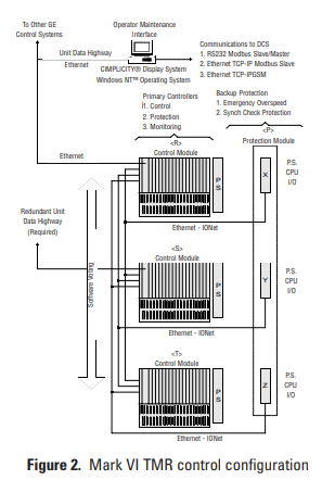
Triple Redundancy
Mark VI control systems are available in
Simplex and Triple Redundant forms for small
applications and large integrated systems with
control ranging from a single module to many
distributed modules. The name Triple Module
Redundant (TMR) is derived from the basic
architecture with three completely separate and
independent Control Modules, power supplies,
and IONets. Mark VI is the third generation of
triple redundant control systems that were pioneered by GE in 1983. System throughput
enables operation of up to nine, 21-slot VME
racks of I/O cards at 40 ms including voting the
data. Inputs are voted in software in a scheme
called Software Implemented Fault Tolerance
(SIFT). The VCMI card in each Control
Module receives inputs from the Control
Module back-plane and other modules via “its
own” IONet.
Data from the VCMI cards in each of the three
Control Modules is then exchanged and voted
prior to transmitting the data to the main
processor cards for execution of the application
software. Output voting is extended to the turbine with three coil servos for control valves and
2 out of 3 relays for critical outputs such as
hydraulic trip solenoids. Other forms of output
voting are available, including a median select
of 4-20ma outputs for process control and 0-
200ma outputs for positioners.
Sensor interface for TMR controls can be either
single, dual, triple redundant, or combinations
of redundancy levels. The TMR architecture
supports riding through a single point failure in
the electronics and repair of the defective card
or module while the process is running. Adding
sensor redundancy increases the fault tolerance
of the overall “system.” Another TMR feature is
the ability to distinguish between field sensor
faults and internal electronics faults.
Diagnostics continuously monitor the 3 sets of
input electronics and alarms any discrepancies
between them as an internal fault versus a sensor fault. In addition, all three main processors
continue to execute the correct “voted” input
data. (See Figure 2.)
I/O Interface
There are two types of termination boards. One
type has two 24-point, barrier-type terminal
blocks that can be unplugged for field maintenance. These are available for Simplex and
TMR controls. They can accept two 3.0 mm2
(#12AWG) wires with 300 volt insulation.
Another type of termination board used on
Simplex controls is mounted on a DIN rail and
has one, fixed, box-type terminal block. It can
accept one 3.0 mm2 (#12AWG) wire or two 2.0
mm2 (#14AWG) wires with 300 volt insulation.
I/O devices on the equipment can be mounted
up to 300 meters (984 feet) from the termination boards, and the termination boards must
be within 15 m (49.2’) from their corresponding I/O cards. Normally, the termination
boards are mounted in vertical columns in termination cabinets with pre-assigned cable
lengths and routing to minimize exposure to
emi-rfi for noise sensitive signals such as speed
inputs and servo loops.
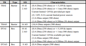
General Purpose I/O
Discrete I/O. A VCRC card provides 48 digital
inputs and 24 digital outputs. The I/O is divided between 2 Termination Boards for the contact inputs and another 2 for the relay outputs.
(See Table 1.)
Analog I/O. A VAIC card provides 20 analog
inputs and 4 analog outputs. The I/O is divided
between 2 Termination Boards. A VAOC is dedicated to 16 analog outputs and interfaces with
1 barrier-type Termination Board or 2 box-type
Termination Boards. (See Table 2.)
Temperature Monitoring. A VTCC card provides interface to 24 thermocouples, and a
VRTD card provides interface for 16 RTDs. The
input cards interface with 1 barrier-type
reduced by eliminating peripheral instrumentation. The VTUR card is designed to integrate
several of the unique sensor interfaces used in
turbine control systems on a single card. In
some applications, it works in conjunction with
the I/O interface in the Backup Protection
Module described below.
Speed (Pulse Rate) Inputs. Four-speed inputs
from passive magnetic sensors are monitored by
the VTUR card. Another two-speed (pulse rate)
inputs can be monitored by the servo card
VSVO which can interface with either passive or
active speed sensors. Pulse rate inputs on the
VSVO are commonly used for flow-divider feedback in servo loops. The frequency range is 2-
14k Hz with sufficient sensitivity at 2 Hz to
detect zero speed from a 60-toothed wheel. Two
additional passive speed sensors can be monitored by “each” of the three sections of the
Backup Protection Module used for emergency
overspeed protection on turbines that do not
have a mechanical overspeed bolt. IONet is
used to communicate diagnostic and process
data between the Backup Protection Module
and the Control Module(s) including cross-tripping capability; however, both modules will initiate system trips independent of the IONet.
(See Table 4 and Table 5.)
Synchronizing. The synchronizing system consists of automatic synchronizing, manual synchronizing, and backup synch check protection. Two single-phase PT inputs are provided
Application Specific I/O
In addition to general purpose I/O, the Mark
VI has a large variety of cards that are designed
for direct interface to unique sensors and actuators. This reduces or eliminates a substantial
amount of interposing instrumentation in
many applications. As a result, many potential
single-point failures are eliminated in the most
critical area for improved running reliability
and reduced long-term maintenance. Direct
interface to the sensors and actuators also
enables the diagnostics to directly interrogate
the devices on the equipment for maximum
effectiveness. This data is used to analyze device
and system performance. A subtle benefit of
this design is that spare-parts inventories are
on the TTUR Termination Board to monitor
the generator and line busses via the VTUR
card. Turbine speed is matched to the line frequency, and the generator and line voltages are
matched prior to giving a command to close the
breaker via the TTUR.
An external synch check relay is connected in
series with the internal K25P synch permissive
relay and the K25 auto synch relay via the
TTUR. Feedback of the actual breaker closing
time is provided by a 52G/a contact from the
generator breaker (not an auxiliary relay) to
update the database. An internal K25A synch
check relay is provided on the TTUR; however,
the backup phase / slip calculation for this relay
is performed in the Backup Protection Module
or via an external backup synch check relay.
Manual synchronizing is available from an operator station on the network or from a synchroscope.
Shaft Voltage and Current Monitor. Voltage can
build up across the oil film of bearings until a
discharge occurs. Repeated discharge and arcing can cause a pitted and roughened bearing
surface that will eventually fail through accelerated mechanical wear. The VTUR / TTUR can
continuously monitor the shaft-to- ground voltage and current, and alarm at excessive levels.
Test circuits are provided to check the alarm
functions and the continuity of wiring to the
brush assembly that is mounted between the
turbine and the generator.
F
Flame Detection. The existence of flame either
can be calculated from turbine parameters that
are already being monitored or from a direct
interface to Reuter Stokes or Honeywell-type
flame detectors. These detectors monitor the
flame in the combustion chamber by detecting
UV radiation emitted by the flame. The Reuter
Stokes detectors produce a 4-20ma input. For
Honeywell flame scanners, the Mark VI supplies
the 335Vdc excitation and the VTUR / TRPG
monitors the pulses of current being generated.
This determines if carbon buildup or other
contaminates on the scanner window are causing reduced light detection.
Trip System. On turbines that do not have a
mechanical overspeed bolt, the control can
issue a trip command either from the main
processor card to the VTUR card in the Control
Module(s) or from the Backup Protection
Module. Hydraulic trip solenoids are wired with
the negative side of the 24Vdc/125Vdc circuit
connected to the TRPG, which is driven from
the VTUR in the Control Module(s) and the
positive side connected to the TREG which is
driven from the VPRO in each section of the
Backup Protection Module. A typical system trip
initiated in the Control Module(s) will cause
the analog control to drive the servo valve actuators closed, which stops fuel or steam flow and
de-energizes (or energizes) the hydraulic trip
solenoids from the VTUR and TRPG. If crosstripping is used or an overspeed condition is
detected, then the VTUR/TRPG will trip one
side of the solenoids and the VPTRO/TREG
will trip the other side of the solenoid(s).
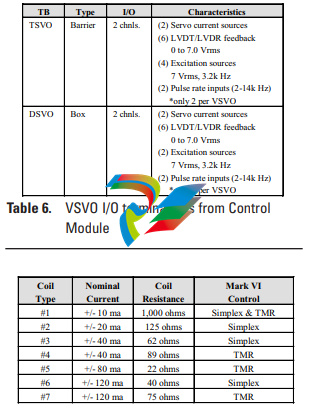
Servo Valve Interface. A VSVO card provides 4
servo channels with selectable current drivers,
feedback from LVDTs, LVDRs, or ratio metric
LVDTs, and pulse-rate inputs from flow divider
feedback used on some liquid fuel systems. In
TMR applications, 3 coil servos are commonly
used to extend the voting of analog outs to the
servo coils. Two coil servos can also be used.
One, two, or three LVDT/Rs feedback sensors
can be used per servo channel with a high select,
low select, or median select made in software. At
least 2 LVDT/Rs are recommended for TMR
applications because each sensor requires an AC
excitation source. (See Table 6 and Table 7.)
Vibration / Proximitor® Inputs. The VVIB card
provides a direct interface to seismic (velocity),
Proximitor®, Velomitor®, and accelerometer
(via charge amplifier) probes. In addition, DC
position inputs are available for axial measurements and Keyphasor® inputs are provided.
Displays show the 1X and unfiltered vibration
levels and the 1X vibration phase angle. -24vdc
is supplied from the control to each Proximitor
with current limiting per point. An optional termination board can be provided with active isolation amplifiers to buffer the sensor signals
from BNC connectors. These connectors can be
used to access real-time data by remote vibration analysis equipment. In addition, a direct
plug connection is available from the termination board to a Bently Nevada 3500 monitor.
The 16 vibration inputs, 8 DC position inputs,
and 2 Keyphasor inputs on the VVIB are divided between 2 TVIB termination boards for
3,000 rpm and 3,600 rpm applications. Faster
shaft speeds may require faster sampling rates
on the VVIB processor, resulting in reduced
vibration inputs from 16-to-8. (See Table 8.)
Three phase PT and CT monitoring. The VGEN
card serves a dual role as an interface for 3
phase PTs and 1 phase CTs as well as a specialized control for Power-Load Unbalance and
Early-Valve Actuation on large reheat steam turbines. The I/O interface is split between the
TGEN Termination Board for the PT and CT
inputs and the TRLY Termination Board for
relay outputs to the fast acting solenoids. 4-
20ma inputs are also provided on the TGEN for
monitoring pressure transducers. If an EX2000
Generator Excitation System is controlling the
generator, then 3 phase PT and CT data is communicated to the Mark VI on the network
rather than using the VGEN card. (See Table 9.)
Optical Pyrometer Inputs. The VPYR card moni
tors two LAND infrared pyrometers to create a
temperature profile of rotating turbine blades.
Separate, current limited +24Vdc and –24Vdc
sources are provided for each Pyrometer that
returns four 4-20ma inputs. Two Keyphasors are
used for the shaft reference. The VPYR and
matching TPYR support 5,100 rpm shaft speeds
and can be configured to monitor up to 92 buckets with 30 samples per bucket. (See Table 10.)
Operator Interface
The operator interface is commonly referred to
as the Human Machine Interface (HMI). It is a
PC with a Microsoft® Windows NT® operating
system supporting client/server capability, a
CIMPLICITY® graphics display system, a
Control System Toolbox for maintenance, and a
software interface for the Mark VI and other
control systems on the network. (See Figure 3.)
It can be applied as:
■ The primary operator interface for
one or multiple units
■
■ A backup operator interface to the
plant DCS operator interface
■ A gateway for communication links to
other control systems
■ A permanent or temporary
maintenance station
■ An engineer’s workstation
All control and protection is resident in the
Mark VI control, which allows the HMI to be a
non-essential component of the control system.
It can be reinitialized or replaced with the
process running with no impact on the control
system. The HMI communicates with the main
processor card in the Control Module via the
Ethernet based Unit Data Highway (UDH). All
analog and digital data in the Mark VI is accessible for HMI screens including the high resolution time tags for alarms and events.
System (process) alarms and diagnostics alarms
for fault conditions are time tagged at frame
rate (10/20/40 ms) in the Mark VI control and
transmitted to the HMI alarm management system. System events are time tagged at frame
rate, and Sequence of Events (SOE) for contact
inputs are time tagged at 1ms on the contact
input card in the Control Module. Alarms can
be sorted according to ID, Resource, Device,
Time, and Priority. Operators can add comments to alarm messages or link specific alarm
messages to supporting graphics.
Data is displayed in either English or Metric
engineering units with a one-second refresh
rate and a maximum of one second to repaint a
typical display graphic. Operator commands
can be issued by either incrementing / decrementing a setpoint or entering a numerical
value for the new setpoint. Responses to these
commands can be observed on the screen one
second from the time the command was issued.
Security for HMI users is important to restrict
access to certain maintenance functions such as
editors and tuning capability, and to limit certain operations. A system called “User
Accounts” is provided to limit access or use of
particular HMI features. This is done through
the Windows NT User Manager administration
program that supports five user account levels.
Software Maintenance Tools
The Mark VI is a fully programmable control
system. Application software is created from inhouse software automation tools which select
proven GE control and protection algorithms
and integrate them with the I/O, sequencing,
and displays for each application. A library of
software is provided with general-purpose
blocks, math blocks, macros, and application
specific blocks. It uses 32-bit floating point data
(IEEE-854) in a QNX operating system with
real-time applications, multitasking, prioritydriven preemptive scheduling, and fast context
switching.
Software frame rates of 10, 20, and 40 ms are
supported. This is the elapsed time that it takes
to read inputs, condition the inputs, execute
the application software, and send outputs.
Changes to the application software can be
made with password protection (5 levels) and
downloaded to the Control Module while the
process is running. All application software is
stored in the Control Module in non-volatile
flash memory.
Application software is executed sequentially
and represented in its dynamic state in a ladder
diagram format. Maintenance personnel can
add, delete, or change analog loops, sequencing logic, tuning constants, etc. Data points can
be selected and “dragged” on the screen from
one block to another to simplify editing. Other
features include logic forcing, analog forcing,
and trending at frame rate. Application software documentation is created directly from
the source code and printed at the site. This
includes the primary elementary diagram, I/O
assignments, the settings of tuning constants,
etc. The software maintenance tools (Control
System Toolbox) are available in the HMI and
as a separate software package for virtually any
Windows 95 or NT based PC. The same tools
are used for EX2000 Generator Excitation
Systems, and Static Starters. (See Figure 4 and
Figure 5.)
Communications
Communications are provided for internal data
transfer within a single Mark VI control; communications between Mark VI controls and
peer GE control systems; and external communications to remote systems such as a plant distributed control system (DCS).
The Unit Data Highway (UDH) is an Ethernetbased LAN with peer-to-peer communication
between Mark VI controls, EX2000 Generator
Excitation Controls, Static Starters, the GE
Fanuc family of PLC based controls, HMIs, and
Historians. The network uses Ethernet Global
Data (EGD) which is a message-based protocol
with support for sharing information with mul
ple nodes based on the UDP/IP standard
(RFC 768). Data can be transmitted Unicast,
Multicast or Broadcast to peer control systems.
Data (4K) can be shared with up to 10 nodes at
25Hz (40ms). A variety of other proprietary
protocols are used with EGD to optimize communication performance on the UDH.
40 ms is fast enough to close control loops on
the UDH; however, control loops are normally
closed within each unit control. Variations of
this exist, such as transmitting setpoints
between turbine controls and generator controls for voltage matching and var/power-factor
c
control. All trips between units are hardwired
even if the UDH is redundant.
The UDH communication driver is located on
the Main Processor Card in the Mark VI. This is
the same card that executes the turbine application software; therefore, there are no potential communication failure points between the
main turbine processor and other controls or
monitoring systems on the UDH. In TMR systems, there are three separate processor cards
executing identical application software from
identical databases. Two of the UDH drivers are
normally connected to one switch, and the
other UDH driver is connected to the other
switch in a star configuration. Network topologies conform to Ethernet IEEE 802.3 standards.
The GE networks are a Class “C” Private
Internet according to RFC 1918: Address
Allocation for Private Internets – February
1996. Internet Assigned Numbers Authority
(IANA) has reserved the following IP address
space 192.168.1.1: 192.168.255.255 (192.168/
16 prefix).
Communication links from the Mark VI to
remote computers can be implemented from
either an optional RS232 Modbus port on the
main processor card in Simplex systems, or
from a variety of communication drivers from
the HMI. When the HMI is used for the communication interface, an Ethernet card in the
HMI provides an interface to the UDH, and a
second Ethernet card provides an interface to
the remote computer.
All operator commands that can be issued from
an HMI can be issued from a remote computer
through the HMI(s) to the Mark VI(s), and the
remote computer can monitor any application
software data in the Mark VI(s). Approximately
500 data points per control are of interest to a
plant control system; however, about 1,200
-
 HIRSCHMANN MSM20-M2M2M2M2SY9HH9E Ethernet media modul
 -
 HIRSCHMANN SPIDER-PL-20-05T1999999TWVHHHH Industrial Ethernet Rail Switch
 -
 Hirschmann SPIDER-PL-20-07T1M2M299TWVHHHH Industrial ETHERNET Rail Switch
 -
.png) Hirschmann (Belden) RS20-1600M2M2SDAEHC09.1.00 DIN-rail managed industrial Fast Ethernet switch
Hirschmann (Belden) RS20-1600M2M2SDAEHC09.1.00 DIN-rail managed industrial Fast Ethernet switch -
 Hirschmann (Belden) RS30-1602O6O6TDAPHC09.1.00 DIN-rail managed industrial Ethernet switch
 -
 Hirschmann (Belden) RS30-2402O6T1SDAPHH09.0.13 DIN-rail industrial Ethernet switch
 -
Hirschmann (Belden) SPIDER-PL-20-04T1S29999TY9HHHH Ethernet DIN-rail switch
-
 HIRSCHMANN RS20-1600T1T1SDAUHX Switch
 -
 HIRSCHMANN BRS42-0012OOOO-SPCZ99HHSES industrial switch
 -
 Hirschmann RS20-0800S2S2TDHPHH09.0.14 Fast Ethernet DIN rail switch.
 -
 HIRSCHMANN MM20-Z6Z6M2M2SAHH Hybrid Fast Ethernet Media Module
 -
 HIRSCHMANN MM20-Z6Z6T1T1SAHH hot-swappable hybrid Fast Ethernet Media Module
 -
 HIRSCHMANN MM20-P9P9T1T1SAHH Hybrid Fast Ethernet Media Module
 -
 HIRSCHMANN MM20-M4T1T1T1SAHH Hybrid Fast Ethernet Media Module
 -
 HIRSCHMANN MM20-M4M4T1T1SAHH Hybrid Fast Ethernet Media Module
 -
 HIRSCHMANN MM20-M2M2M2M2SZHH Ethernet media module
 -
HIRSCHMANN MM20-M2M2M2M2SAHH Ethernet media module
-
 HIRSCHMANN MM20-T1T1T1T1EBH 4-port Fast Ethernet Copper Cable Media Module
 -
HIRSCHMANN MM20-T1T1T1T1SAHH 4-port Fast Ethernet Copper Cable Media Module
-
HIRSCHMANN MM20-T1T1T1T1SAHH 4-port Fast Ethernet Copper Cable Media Module
-
 HIRSCHMANN MM20-Z6Z6EBH Hot-swappable fast Ethernet media module
 -
 HIRSCHMANN MM20-Z6Z6SAHH Ethernet media module
 -
HIRSCHMANN MM20-Z6Z6Z6Z6EBH Industrial Media Module
-
 MSM40-T1T1T1TZ9HH9E99.9.99 HIRSCHMANN Switch
 -
 HIRSCHMANN MS20-0800SAAEHC / MS20-0800SAAEHC0 8-port modular Layer 2 management Ethernet switch
 -
 Hirschmann RSPM20-4T14T1SZ9HHS9 Switch RSPM20-4T14T1SZ9HHS9
 -
 HIRSCHMANN RS20-1600M2M2SDAEHH09.1. RS20/30/40 Managed Switch configurator
 -
HIRSCHMANN RS20-1600M2M2SDAEHX09.0.00 Ethernet switch
-
 HIRSCHMANN BELDEN SPIDER-PL-20-07T1M2M299TY9HHHH / SPIDERPL2007T1M2M299TY9HHHH
 -
HIRSCHMANN MM3-1FXS2/3TX1 Switching Board Module
-
 HIRSCHMANN RSPE30-24044O7T99-ECCP999HHSE2A08.1.00 Industrial-grade fanless management-type Ethernet switch
 -
 HIRSCHMANN RS30-1602OOZZSDAEHC09.1.00 DIN-rail-mounted managed Layer 2 Ethernet switch
 -
 HIRSCHMANN MACH104-20TX-F Managed 24-port Full Gigabit 19" Switch
 -
 HIRSCHMANN Switch RS20-0800M4M4SDAE
 -
Hirschmann RS30-1602O6O6SDAEHH09.1. Management-type Ethernet switch
-
 Hirschmann RS30-1602OOZZSDAEHC09.0.10 Open rack-style Ethernet switch
 -
 HIRSCHMANN RSPE30-24044O7T99-SCCV999HHSI2SXX.X.XX High-Availability Seamless Redundancy
 -
HIRSCHMANN RSPE30-24044O7T99-SCCZ999HHSE2A DIN-rail Ethernet switch
-
HIRSCHMANN MM2-4TX1-EEC switch
-
HIRSCHMANN MSM40-T1T1T1T1TZ9HH9E99.9.99 Module
-
 HIRSCHMANN RS20 Rail Switch RS20-0400S4T1SDAEHC07.1.01
 -
 HIRSCHMANN M4-FAST8-SFP Fast Ethernet media module
 -
 HIRSCHMANN RS20-0400M2T1SDAP Managed Fast-Ethernet-Switch
 -
 HIRSCHMANN BELDEN SPIDER II 8TX/1FX EEC Industrial Ethernet Rail Switch
 -
HIRSCHMANN MM3-2FXS2/2TX1
-
 HIRSCHMANN RS2-4TX/1FX EEC Industrial Ethernet Rail Switch
 -
 RS30-0802O6O6SDAEHC09.0.10 HIRSCHMANN Switch
 -
 HIRSCHMANN m4-8TP-RJ45 Ethernet Media Module
 -
 HIRSCHMANN MSP30-24040SCZ9URHHE3A switch
 -
 Hirschmann rack MS30-1602SAAPHC
 -
 HIRSCHMANN RS2-FX/FX Industrial Switch Module
 -
Rs1txfx - Hirschmann - Rs1-Tx/Fx Rail Switch
-
RS20-0800S2S2SDAEHC09.1.00 HIRSCHMANN Commutator
-
 Hirschmann EAGLE20 TX/TX Industrial Security Router
 -
 Hirschmann SPIDER-SL-20-04T1S29999SY9HHHH Industrial Switch
 -
 HIRSCHMANN MAR1040-4C4C4C4C9999SMMHRHHXX.X. Gigabit Ethernet Switch configurator
 -
 Hirschmann MAR1040 Industrial Switch
 -
 HIRSCHMANN BELDEN RS30-1602O6O6SDAE
 -
Hirschmann RS20-1600M2M2SDAUHC Ethernet DIN rail switch
-
 HIRSCHMANN OCTOPUS 24M industrial switch
 -
 HIRSCHMANN RS20-1600T1T1SDAE Management-type Ethernet switch
 -
 HIRSCHMANN RS20-1600T1T1SDAUHH industrial switch
 -
HIRSCHMANN RS20-0800M2M2SDAPHC09.0.04 switch
-
 Hirschmann MR 8-03 24V DC Industrial Modular Bridge/Router
 -
 HIRSCHMANN RS20-0400M2T1SDAPHC08.0.01 Managed Switch
 -
 MACH1130 Hirschmann Industrial Switch
 -
 HIRSCHMANN 943824-002 SPIDER 5TX Industrial Ethernet Switch
 -
 HIRSCHMANN RS30-0802O6O6SDAEHC09.1.00 Managed Industrial Switch
 -
 HIRSCHMANN RS20-0400M2M2TDAEHC04.0.01 Industrial Switch
 -
 HIRSCHMANN BRS20-0600Z6Z6-STCZ99HHSES Industrial Switch
 -
 HIRSCHMANN MACH104-20TX-FR-L3P Industrial Ethernet Switch
 -
 HIRSCHMANN RS40-0009CCCCEDBPHH06.0.01 Industrial Switch
 -
 HIRSCHMANN RS2-3TX/2FX EEC Industrial Ethernet Switch
 -
 Hirschmann MACH 1020/1030 Fast/Gigabit Rack Mount Switches
 -
HIRSCHMANN RS20-0800M2M2SDAPHC09.0.14 Industrial Switch
-
 HIRSCHMANN RS20-1600T1T1SDAEHC09.0.04 Industrial Switch
 -
 HIRSCHMANN RSB20-0800T1T1EAABHH Industrial Switch
 -
 HIRSCHMANN MACH4002-48+4G-L3E Industrial Backbone Switch
 -
 HIRSCHMANN RS20-0400S2T1SDAE Industrial Managed Switch
 -
HIRSCHMANN RS20-0800S2T1SDAUHC Industrial Switch
-
 HIRSCHMANN RS20-2400S4S4SDAEHC09.0.14 industrial switch
 -
 HIRSCHMANN OS20-001200T5T5T5- TBBZ999HHNE3S 08.1.00 industrial switch
 -
HIRSCHMANN OS20-001200T5T5T5- TBBZ999HHNE3S 08.1.00 industrial switch
-
 HIRSCHMANN RS40-0009CCCCSDAEHH09.0.14 switch
 -
 Hirschmann RS20-1600T1T1SDAUHC Management-type Ethernet Switch
 -
 Hirschmann M1-8SFP Switche
 -
Hirschmann Industrial Ethernet Ruggedized Switch MACH1000 Family
-
 Basler Electric, Solid State Protective Relay, BE1-60
 -
BASLER ELECTRIC SR4A-2B15B3A Static Voltage Regulator
-
.png) BASLER ELECTRIC EXCITER DIODE MONITOR EDM-200
BASLER ELECTRIC EXCITER DIODE MONITOR EDM-200 -
.png) BASLER ELECTRIC DECS125-15-B2C5 DIGITAL EXCITATION CONTROL SYSTEM V 2.0.9
BASLER ELECTRIC DECS125-15-B2C5 DIGITAL EXCITATION CONTROL SYSTEM V 2.0.9 -
 BASLER ELECTRIC BE1-851 OVERCURRENT PROTECTION RELAY MECHANISM
 -
 Basler Electric BE1-51A / BE151A
 -
 Basler Electric BE1-40Q Loss of Excitation Relay
 -
 Basler Electric BE1-87G Variable Percentage Differential Relay
 -
 Basler Electric BE1-11 Protection System I5A3M2P2N0EA00
 -
 BASLER ELECTRIC DECS-200-1C Digital Excitation Control System
 -
 Basler Electric / Kohler BE1-11g Generator Protection Relay G5A3M2J2N0E000
 -
BASLER ELECTRIC DECS125-15 DIGITAL EXCITATION CONTROL SYSTEM
-
 BASLER ELECTRIC BE1-951 OverCurrent Protecton System
 -
Basler Electric DECS-200-1L Digital Excitation Control System
-
 Basler Electric DGC-2020HD-5NS1DNSBA Digital Genset Controller -
 -
 BASLER ELECTRIC BE1-81T1EE1WA0N1F / BE181T1EE1WA0N1F
 -
 BASLER ELECTRIC BE1-25M1EA6PN5R1F / BE125M1EA6PN5R1F
 -
 BASLER ELECTRIC DECS-250-LN1SN1N DIGITAL EXCITATION CONTROL SYSTEM
 -
Basler Electric DECS-250-CN2CN 1N Digital Excitation Control System Unit
-
 BASLER ELECTRIC DECS-300-C0N0 DIGITAL EXCITATION CONTROL SYSTEM
 -
 BASLER ELECTRIC BE1-87T-A1E-A1J-D0S1F / BE187TA1EA1JD0S1F
 -
BASLER ELECTRIC BE1-11-G6D1M0J2P0E000 Protection System
-
 BASLER ELECTRIC BE1-GPS100-E4N1H1N GENERATOR PROTECTION SYSTEM
 -
 Jaquet Relay card (Auxiliary module) FTV 3090 377Z-03985
 -
 Jaquet Trip Chain Control card FTBU 3034 377Z-05030
 -
 Jaquet with input card -E04 FTFU 3024 -E04 377Z-05855
 -
 Jaquet with input card -E03 FTFU 3024- E03 377Z-03983
 -
 Jaquet FTFU 3024- E02 377Z-03982 with input card -E02
 -
 Jaquet FTFU 3024-E01 377Z-03981 with input card -E01
 -
 Hirschmann RS20-2400T1T1SDAE Industrial Managed Ethernet Switch
 -
 Hirschmann BELDEN EAGLE30-04022O6TT999SCCV9HSE3F
 -
 Hirschmann MM3-2FXS2/2TX MICE Media Module
 -
 Hirschmann RS20-1600M2M2SDAPHC08.0.05 Industrial Managed Switch
 -
 Hirschmann OZD Profi 12M G12-1300 PRO Fieldbus Repeater
 -
Hirschmann SPIDER 4TX/1FX-ST EEC Industrial Ethernet Switch
-
 Hirschmann MM2-2FXM3/2TX1 MICE Media Module
 -
 Hirschmann RS20-2400M2M2SDAPHC09.0.14 Industrial Switch
 -
 Hirschmann RS20-0400M2M2SDAEHC07.1.05 OpenRail Switch
 -
 Hirschmann OZD Profi 12M G12-EEC Fieldbus Repeater
 -
HIRSCHMANN MDA422-1/2-3.5c-23/46 sensor
-
Hirschmann RS30-2402T1T1SDAUHC Managed Industrial Switch


