
parkerVM600Mk2 MPC4Mk2 + IOC4Mk2 machinery protection modules
KEY FEATURES AND BENEFITS
• VibroSight® compatible hardware from the
vibro-meter® product line
• VM600Mk2 (second generation)
machinery protection modules
• 4 dynamic channels and 2 auxiliary channels
configurable as either tachometer inputs or
DC inputs
• VM600Mk2 system safety-line to drive all system
relays to a safe state
• Diagnostics (built-in self-test (BIST)) provides
continuous feedback on the health of the
modules
• Individually configurable inputs (with sensor
power supply outputs), channel filters,
processing and outputs – with simultaneous
data acquisition (fixed frequency or
order tracked)
• Up to 10 processed outputs per channel
• Multiple alarms per processed output with
configurable limits, hysteresis and time delay
• AND, OR and majority voting logic functions for
the combination of alarm and status
information
KEY BENEFITS AND FEATURES (continued)
• Discrete outputs: 4 user-configurable relays for
use by alarms and 1 common circuit-fault
relay
• Analog outputs: 4 outputs configurable as
either 4 to 20 mA or 0 to 10 V
• Conforms to API 670
• Direct system Ethernet communications
• Compatible with VM600Mk2 system racks
(ABE04x) and slimline racks (ABE056)
KEY BENEFITS AND FEATURES (continued)
• Live insertion and removal of modules
(hot-swappable)
• Software configurable
APPLICATIONS
• VM600Mk2 machinery protection
(Q1 2021)
• VM600Mk2 machinery protection and/or
condition monitoring (Q3 2021)
• Vibration and/or combustion monitoring
• API 670 applications
DESCRIPTION
Introduction
The VM600Mk2 MPC4Mk2 + IOC4Mk2 machinery
protection modules are designed for operation
with the second generation of VM600Mk2 rackbased machinery protection system (MPS), from
Meggitt’s vibro-meter® product line. The
MPC4Mk2 + IOC4Mk2 are second generation
modules (cards) that provide 4 dynamic and 2
auxiliary channels of machinery protection and
basic condition monitoring in VM600Mk2 systems.
VM600Mk2 rack-based monitoring systems
The vibro-meter® VM600Mk2 rack-based
monitoring system is the evolution of Meggitt’s
solution for the protection and monitoring of
rotating machinery used in the power generation
and oil & gas industries. VM600Mk2 solutions are
recommended when a centralised monitoring
system with a medium to large number of
measurement points (channels) is required. It is
typically used for the monitoring and/or
protection of larger machinery such as gas,
steam and hydro turbines, and generators,
smaller machines such as compressors, fans,
motors, pumps and propellers, as well as balanceof-plant (BOP) equipment.
A VM600Mk2 system consists of a 19" rack, a rack
power supply and one or more monitoring
modules. Optionally, relay modules and rack
controller and communications interface
modules can also be included.
Two types of rack are available: a VM600Mk2
system rack (ABE04x, 6U) that can house up to
twelve monitoring modules, and a VM600Mk2
slimline rack (ABE056, 1U) that can house one
monitoring module. The racks are typically
mounted in standard 19" rack cabinets or
enclosures installed in an equipment room.
Different VM600Mk2 monitoring modules are
available for machinery protection, condition
monitoring and/or combustion monitoring
applications. For example, machinery protection
modules such as the MPC4Mk2 + IOC4Mk2
modules, and condition monitoring modules such
as the XMV16 + XIO16T monitoring modules for
vibration and XMC16 + XIO16T monitoring
modules for combustion.
The RLC16Mk2 relay module is an optional module
used to provide additional relays when the four
user-configurable relays per set of
MPC4Mk2 + IOC4Mk2 modules is not sufficient for
an application.
The CPUx + IOCx rack controller and
communications interface modules (CPUM/IOCN
and CPUMk2 + IOCMk2) are optional modules used
to provide additional VM600Mk2 system
functionality such as configuration management,
“hot-swapping” with automatic reconfiguration
(to be implemented for VM600Mk2), front-panel
display, CPUx + IOCx modules redundancy,
fieldbus data processing, front-panel alarm reset
(AR) button, MPS rack (CPUx) security, system
event and measurement event logging, fieldbus
communications (Modbus, PROFIBUS and/or
PROFINET) and/or communications redundancy.
Note: Different versions of CPUx + IOCx rack
controller and communications interface
modules support different combinations of
VM600Mk2 system functionality. VM600Mk2 systems
are compatible with CPUMk2 + IOCMk2 modules.
VM600Mk2 rack-based monitoring systems
complement the VibroSmart® distributed
monitoring systems that are also available from
Meggitt’s vibro-meter® product line, and are
compatible with the same VibroSight® machinery
monitoring software suite.
MPC4Mk2 + IOC4Mk2 machinery protection
modules and VM600 racks
The MPC4Mk2 + IOC4Mk2 machinery protection
modules monitor and protect rotating machinery
as part of a VM600Mk2 rack-based monitoring
system.
The MPC4Mk2 module is always used with an
associated IOC4Mk2 module as a set of modules.
Both the MPC4Mk2 and the IOC4Mk2 are singlewidth module that occupy a single VM600Mk2
rack slot (module position). The MPC4Mk2 is
installed in the front of a VM600Mk2 rack and the
associated IOC4Mk2 is installed in the rear of the
rack, in the slot directly behind the MPC4Mk2.
Each module connects directly to the rack’s
backplane using two connectors.
Note: The MPC4Mk2 + IOC4Mk2 modules are
compatible with all VM600Mk2 racks (ABE04x
system racks and ABE056 slimline racks) and later
VM600 racks.
System communications
In a VM600Mk2 system (one or more
MPC4Mk2 + IOC4Mk2 modules and any associated
RLC16Mk2 modules), the main communications
interface is the LAN (Ethernet) connector on the
front panel of each MPC4Mk2 module, which is
used for used for communication with the
VibroSight® software running on an external
computer.
In a VM600Mk2 rack (ABE4x), the VME bus can be
used to share information between modules in
the rack. For example, an MPC4Mk2 + IOC4Mk2
module can provide information such as
measurement, alarm and/or status data to a set
of CPUMk2 + IOCMk2 modules which can then
share the information via one of its industry
standard fieldbuses.
In a VM600Mk2 system (one or more
MPC4Mk2 + IOC4Mk2 modules and any associated
MPC4Mk2 modules), the RLC16Mk2 modules are
controlled and operated by a MPC4Mk2, as
determined by the configuration. The VM600Mk2
rack’s Open collector (OC) bus and Raw bus are
used to exchange control and status information
between the MPC4Mk2 + IOC4Mk2 and RLC16Mk2
modules.
Relays
The MPC4Mk2 + IOC4Mk2 machinery protection
modules include five relays. The four userconfigurable relays (RL1 to RL4) can be used by a
VM600Mk2 system to remotely indicate system
alarm and/or status information. While, a
common circuit-fault relay (FAULT) is used to
indicate a problem with the MPC4Mk2 + IOC4Mk2
modules as detected by the internal diagnostics
(BIST).
The relays in a VM600Mk2 system (specifically one
or more sets of MPC4Mk2 + IOC4Mk2 modules and
any associated RLC16Mk2 modules), are driven by
control circuitry that supports a VM600Mk2 system
safety-line, that is, a system-wide control signal
that automatically drives all system relays
(IOC4Mk2 and RLC16Mk2) and analog outputs
(IOC4Mk2) to a safe state should a problem be
detected. In this way, IOC4Mk2 and RLC16Mk2
relays configured as normally energised (NE) can
always be de-energised in the event of a problem
with one of the components of the relay coil
control signal.
Note: This supports the “de-energise to trip
principle” required in safety-related applications.
Software
MPC4Mk2 + IOC4Mk2 modules, as part of a
VM600Mk2 system), are software configured using
the VibroSight® software.
To meet stringent cybersecurity and API 670
requirements, MPC4Mk2 + IOC4Mk2 modules
segregate machinery protection (MPS) and
condition monitoring (CMS) by using separate
configurations and different VibroSight
configuration software:
• VibroSight Protect supports the configuration
and operation of the machinery protection (MPS)
functionality for a VM600Mk2 system.
• VibroSight Capture supports the configuration
and operation of the condition monitoring (CMS)
functionality for a VM600Mk2 system.
• Other VibroSight software modules support
operations such as data display and analysis
(VibroSight Vision), data logging and postprocessing (VibroSight Server) system
maintenance (VibroSight System Manager), etc.
DESCRIPTION (continued)
More generally for extended condition monitoring
system (CMS) applications, the VibroSight
software supports the configuration and
operation of XMx16/XIO16T modules for condition
monitoring and/or combustion monitoring,
including the processing and presentation of
measurement data for analysis. VibroSight is also
used to configure and manage CPUMk2 + IOCMk2
modules.
Note: The VibroSight® software is also from the
vibro-meter® product line.
Applications information
As part of a VM600Mk2 system,
MPC4Mk2 + IOC4Mk2 machinery protection
modules are ideal for the monitoring and
protection of critical assets such as gas, steam or
hydro turbines and other high-value rotating
machines in a wide range of industrial
applications.
For further information, contact your local
Meggitt representative
Supported sensors
Currently available : Compatible with a wide range of sensors and measurement chains
with current (2-wire) or voltage (3-wire) outputs, including the
following sensors from the Meggitt vibro-meter® product line:
• CAxxx vibration sensors (piezoelectric accelerometers)
• CExxx and PVxxx vibration sensors (piezoelectric accelerometers
and velocity sensors)
• CVxxx and VExxx vibration sensors (velocity sensors)
• CPxxx dynamic pressure sensors (piezoelectric pressure sensors)
• TQxxx proximity sensors
• LSxxx air-gap sensors.
Dynamic inputs
Number of channels : 4 (independent channels)
Voltage inputs
• DC measurement range : 0 to +20 VDC or 0 to −20 VDC.
Note: 10 Hz DC filter (see DC filtering on page 5).
• AC measurement range : ±20 VPEAK-PEAK
• AC + DC measurement range : ±24 VPEAK-PEAK
Common-mode voltage range : −50 to +50 VDC
Common-mode rejection ratio (CMRR) : >55 dB, up to 60 Hz.
>60 dB, from 45 to 65 Hz.
Current inputs
• DC measurement range : 0 to 35 mA
• AC measurement range : ±30 mAPEAK-PEAK
• AC + DC measurement range : ±50 mAPEAK-PEAK
Frequency bandwidth : DC to 20 kHz
Input impedance
• Voltage : ≥100 kΩ, between the differential (high and low) inputs
• Current : 200 Ω ±0.2%
Accuracy
• Amplitude : ±1% of full scale
• Phase : ±1° from 10 Hz to 2 kHz.
±15° from 2 to 20 kHz.
Dynamic input range : ≥80 dB, from 3 Hz to 20 kHz
DC filtering
DC filter
• Cutoff frequency (−3 dB) : 10 Hz ±3.5 Hz
• Roll-off : −40 dB/decade (second order)
Note: The DC filter is used to extract the DC part of a dynamic input when it is configured as a DC input.
High-pass filtering
High-pass filter
• Cutoff frequency (−3 dB) : 0.1, 1 or 3 Hz (or bypassed)
• Roll-off : −20 dB/decade (first order)
• Phase error : <1° at 100 times the cutoff frequency (10, 100 or 300 Hz)
Note: The high-pass filter is used to configure a dynamic input for an AC only input signal with one of 3 different
cutoff frequencies. This filter can be disabled in order to allow the DC-coupling of the input signal (AC + DC)
Auxiliary inputs
Number of channels : 2 (independent channels)
configurable as either tachometer inputs or DC inputs
Common-mode voltage range : −50 to +50 VDC
Common-mode rejection ratio (CMRR) : >50 dB, up to 60 Hz.
>55 dB, from 45 to 65 Hz.
Tachometer input
• Triggering method : Crossing of threshold on rising edge or falling edge of signal
• Triggering threshold : 2/3 of peak-peak value ±10% for rising edge.
1/3 of peak-peak value ±10% for falling edge.
• Tachometer range (on input) : 2 Hz to 50 kHz
• Speed / frequency measurement
range
: 1 to 65535 RPM / 1 Hz to 1092 Hz.
Note: After division by number of wheel teeth (1 to 255).
• Voltage range : 0.6 to 50 VPEAK-PEAK from 2 Hz to 10 kHz.
2 to 50 VPEAK-PEAK from 10 kHz to 50 kHz.
Auxiliary input
• Current range input : ±50 mAPEAK-PEAK (AC + DC measurement range)
• Voltage range input : ±50 VPEAK-PEAK
DC input
• Voltage measurement range : 0 to +20 VDC or 0 to −20 VDC.
Note: 10 Hz DC filter (see DC filtering on page 6).
• Current measurement range : ±50 mAPEAK-PEAK (AC + DC input)
Input impedance
• Voltage : ≥100 kΩ, between the differential (high and low) inputs
• Current : 200 Ω ±0.2%
Dynamic input range : ≥72 dB
DC filtering
DC filter
• Cutoff frequency (−3 dB) : 10 Hz ±3.5 Hz
• Roll-off : −40 dB/decade (second order)
Note: The DC filter is used to extract the DC part of an auxiliary input when it is configured as a DC input.
Sensor/measurement chain OK check
Number of levels : Up to 16 configurable threshold levels (16 DC regions)
OK level range
• Voltage inputs : ±20 VDC
• Current inputs : 0 to 23 mA
Operating principle
• SIL safety sensors : Line-fault detection of conditions such as a problem with the sensor
and/or cabling, problem with the signal conditioner, and/or other
problem with the measurement chain or power supply.
Note: Requires a SIL safety sensor/measurement chain that
provides a suitable diagnostic signal (DC bias level), for example,
measurement chains using IPC707 or IQS900 signal conditioners.
• Standard sensors : Powered sensors – line-fault detection of conditions such as
open-circuit or short-circuit.
Unpowered sensors – line-fault detection of conditions such as
open-circuit.
Digital signal processing
Analogue to digital converter (ADC) : 24 bit
Dynamic range : ≥80 dB
Frequency bandwidth : 0 Hz to 20 kHz
Accuracy
• Amplitude : ≤1% of input full scale
• Phase : ≤1.5°
Digital filtering
• Notch filter : 50 or 60 Hz
• ISO 2954 filter : 10 Hz to 1 kHz (−3 dB), −24 dB/octave
• Band-pass filter : <0.1 dB ripple in pass band, >55 dB attenuation in stop band, 0.1 or
3 dB attenuation at cutoff, −24 to −60 dB/octave slope
• High-pass filter : 0.25 to 400 Hz
• Low-pass filter : 10 Hz to 20 kHz
Measurement resolution : 2048 point waveform / 800 line spectrum
FFT window : Hanning
FFT resolution : 800 spectral lines
Integration count : 0, 1 or 2
Qualifiers (rectifiers) : RMS, Peak, Peak-Peak and Average.
Scaled Peak, Scaled Peak-Peak and Scaled Average.
Extracted data (measurements) : 2 to 10 processed outputs per channel/processing function.
See Processing functions on page 7.
Extracted data type : Scalar, Vector
Order tracking : Digital resampling
Update rate (internal) : 20 ms min. for time domain processing.
100 ms min. for frequency domain processing.
VibroSight® software update rate
(external)
: Configurable as 100 ms, 200 ms, 500 ms, 1 s, 2 s, 5 s, 10 s, 20 s, 50 s, …
Processing functions
The following configurable signal processing blocks and measurements are supported by the
MPC4Mk2 + IOC4Mk2 modules: •
Single-channel processing
Bearing absolute vibration (BAV) – fixed frequency or order tracked
• Dynamic channels only (piezoelectric vibration sensors)
• ISO 2954 or band-pass filtering
• Up to 10 measurements for fixed-frequency data acquisition: up to 6 time-domain measurements (2 direct
and 2 per integration level) and up to 4 frequency-domain measurements
• Up to 6 measurements for order-tracked data acquisition: up to 2 time-domain measurements (2 direct) and
up to 4 frequency-domain measurements
• 1 speed measurement from the associated tachometer.
•
Broad-band pressure (BBP) – fixed frequency or order tracked
• Dynamic channels only (dynamic pressure sensors)
• Band-pass and notch filtering
• Up to 6 measurements for fixed-frequency or order-tracked data acquisition:
up to 2 time-domain measurements and up to 4 frequency-domain measurements
Shaft relative vibration (SRV) – fixed frequency or order tracked
• Dynamic channels only (proximity sensors)
• Band-pass filtering
• Up to 6 measurements for fixed-frequency or order-tracked data acquisition:
up to 2 time-domain measurements and up to 4 frequency-domain measurements (AC displacement)
• 1 quasi-static measurement (DC gap)
• 1 speed measurement from the associated tachometer.
Note: Shaft relative vibration (SRV) processing outputs include both dynamic (AC) and quasi-static (DC)
components.
•
Position/displacement (PS)
• Dynamic or auxiliary channels
• 1 quasi-static measurement (DC gap).
Note: Position/displacement processing is equivalent to the DC gap component of Shaft relative vibration
(SRV) processing.
•
Shaft axial position – collar (SAPC)
• Dynamic or auxiliary channels
• 1 quasi-static measurement (position).
•
Shaft axial position – shaft end (SAPS)
• Dynamic or auxiliary channels
• 1 quasi-static measurement (position).
•
Rotor position (RPS)
• Dynamic or auxiliary channels
• 1 quasi-static measurement (position).
•
Differential expansion – collar (DE)
• Dynamic or auxiliary channels
• 1 quasi-static measurement (position).
•
Rotor expansion – collar (RE)
• Dynamic or auxiliary channels
• 1 quasi-static measurement (position).
•
Quasi-static pressure (QSP)
• Dynamic or auxiliary channels
• 1 quasi-static measurement (position).
•
Quasi-static temperature (QST)
• Dynamic or auxiliary channels
• 1 quasi-static measurement (position).
•
Speed (SP)
• Auxiliary channels only
• 1 speed measurement.
Multi-channel processing
Shaft absolute vibration (SAV)
• Two dynamic channels only – of types BAV and SRV
• Identical filter types and cut off frequencies
• 1 time-domain measurement.
•
X-Y shaft relative processing (SMAX)
• Two dynamic channels only – of type SRV
• Identical filter types and cut off frequencies
• 1 time-domain Smax measurement:
Smax (PEAK-PEAK) according to ISO 7919-1 Method B, or
Smax (PEAK) or Smax (PEAK-PEAK) according to ISO 7919-1 Method C.
Dual mathematical function (DMF)
• Two dynamic channels only
• Identical processing types and rectifier types
• 1 mathematically calculated measurement:
Sum, Subtraction, RMS Sum, RMS Subtraction, Min or Max.
Differential housing expansion (DHE)
• Two dynamic channels only
• Identical processing types and rectifier types
• 1 mathematically calculated measurement:
Sum, Subtraction, RMS Sum, RMS Subtraction, Min or Max.
Notes
In general, MPC4Mk2 + IOC4Mk2 modules support one processing block per input channel.
A maximum of 6 processing blocks can be configured per MPC4Mk2 module. A maximum of 3 multi-channel
processing blocks can be configured per MPC4Mk2 module (two for dynamic input channels and one for
auxiliary input channels). There are 2 to 10 processed outputs (data extractions) per processing function,
depending on the function.
Alarm processing
Alarms : Alarm with configurable limits (severity levels), hysteresis and time
delay per processed output (data extraction)
Time delay : Up to 60 s in steps of 100 ms
Hysteresis : Up to 20% of the alarm level (physical quantity)
Severity levels
• Machinery protection applications : Out of range+, Danger+, Alert+,
Normal,
Alert−, Danger−, Out of range−
• Basic condition monitoring
applications
: Out of range+, Danger+, Alert+, Information+,
Normal,
Information−, Alert−, Danger−, Out of range−
Adaptive monitoring : Adaptive monitoring uses a control parameter provided by an
auxiliary channel (typically speed) to multiply the configured alarm
limits by multiple coefficients configured for different ranges of the
control parameter.
Trip multiplier uses the DSI TM control signal to multiply the
configured alarm limits by a single configurable coefficient.
See Discrete signal interface (DSI) inputs on page 10.
Alarm combination
Logic functions : AND, OR and majority voting logic (1oo2, 2oo2 and 2oo3), with
optional inversion of individual inputs
Level 1 (basic) logic functions
• Number : 32
• Number of inputs per logic function : 32
• Configurable inputs : Sensor OK checks, measurement alarms (such as Danger+, Alert+,
Alert− and Danger−) and/or associated data quality indicators
(status bits)
Level 2 (advanced) logic functions
• Number : 32
• Number of inputs per logic function : 32
• Configurable inputs : Outputs from level 1 (basic) logic functions.
Note: Level 1 (basic) and level 2 (advanced) logic functions can
be combined to generate more complex logic function.
Alarm update rate (internal) : 100 ms max.
Note: This is the time required for MPC4Mk2 + IOC4Mk2 modules to
detect and initiate an alarm, including output relay (RL1 to RL4)
activation.
Discrete signal interface (DSI) inputs
Control signal
• Alarm bypass (AB) : A closed contact between the DSI AB and RET inputs inhibits the
activation of alarms and relays on MPC4Mk2 + IOC4Mk2 modules.
Note: The common circuit-fault relay (FAULT) is activated when
Alarm bypass (AB) is enabled.
• Alarm reset (AR) : A closed contact between the DSI AR and RET inputs resets (clears)
the alarms and relays latched by MPC4Mk2 + IOC4Mk2 modules.
Note: The Alarm reset (AR) input is edge-sensitive and a high-to-low
transition is required to activate the reset. The Alarm reset (AR) input
should not be held low and must transition low-to-high before
another reset (high-to-low) can activate the reset.
• Trip multiply (TM) : A closed contact between the DSI TM and RET inputs multiplies the
configured alarm levels for MPC4Mk2 + IOC4Mk2 modules by a scale
factor (software configurable)
Operating principle : Detection of an open circuit or a closed circuit on the input
Buffered outputs – dynamic channels
Number : 4
Type : Buffered outputs (buffered “raw” analog signal).
Buffered analog signals corresponding to dynamic channel input
channels (CH1 to CH4) are available on BNC connectors on the
MPC4Mk2 module (front of rack) and on the J2 screw-terminal
connector on the IOC4Mk2 module (rear of rack).
See Connectors on page 17.
Frequency bandwidth : DC to 60 kHz
Output impedance : <5 Ω
Accuracy
• Amplitude : ± 0.1 dB up to 20 kHz.
± 3 dB from 20 to 60 kHz.
• Phase : <1° from 10 Hz to 2 kHz.
<15° from 2 to 20 kHz.
Transfer ratios
• Voltage input : 1 V/V
• Current input : 0.2 V/mA
Admissible load on output
• Resistance : ≥50 kΩ
• Capacitance : Able to drive up to 3 m of cable with a typical capacitance
of 100 pF/m
• Impedance : >50 kΩ with a load capacitance <5 nF
Buffered outputs – auxiliary channels
Number : 2
Type : Buffered outputs (buffered “raw” analog signal or TTL-level signal).
Buffered analog signals corresponding to auxiliary input
channels (AX1 and AX2) are available on BNC connectors on the
MPC4Mk2 module (front of rack) and on the J2 connector on the
IOC4Mk2 module (rear of rack).
See Connectors on page 17.
Note: When an auxiliary input is configured as a tachometer input,
a buffered TTL-level signal corresponding to the auxiliary input
channel (AX1 or AX2) is available on the J2 connector on the
IOC4Mk2 module (rear of rack). When an auxiliary input is
configured as a DC input, no digital TTL-level signal is available.
Frequency bandwidth : DC to 60 kHz
Output impedance
• Buffered TTL-level signal
(tachometer input)
: <300 Ω
• Buffered “raw” analog signal
(DC input)
: <5 Ω
Signal levels : 0 to 5 V TTL-compatible signal (non-inverting)
Admissible load on output
• Resistance : >50 kΩ
• Capacitance : Able to drive up to 3 m of cable with a typical capacitance
of 100 pF/m
• Impedance : >50 kΩ with a load capacitance <5 nF
Analog outputs
Number of local outputs : 4 single-ended outputs.
Used to output quasi-static measurement signals (DC).
Individually configurable as either current or voltage output signals.
Current outputs
• Range : 4 to 20 mA.
Two modes of operation are supported, as follows:
• Mode 1, measured value with quality checks – the analog output
is driven in the 4 to 20 mA signal range during normal operation,
and the analog output is driven to 2 mA to indicate a problem.
• Mode 2, measured value without quality checks – the analog
output is driven in the 2 to 23 mA signal range.
Note: Current outputs are 0 mA ± 0.5 mA when disabled.
• Resolution : 10 µA
• Accuracy : ≤1% of full scale
• Admissible load on output : >360 Ω
Voltage outputs
• Range : 0 to 10 V.
Note: Voltage outputs are 0 V ± 10 mV when disabled.
• Resolution : 2.5 mV
• Accuracy : ≤1% of full scale
• Admissible load on output : >50 kΩ with a load capacitance <5 nF
Update rate / frequency bandwidth : 100 ms / 10 Hz max.
Short-circuit protection : Yes
Discrete outputs
Relays
• Number : 5.
4 × output relays (RL1 to RL4) – suitable for alarm and/or
status outputs.
1 × common circuit-fault relay (FAULT) – for fault indication.
See Relay characteristics on page 14.
• Configurable functions : Normally energized (NE) or normally de-energized (NDE).
Latched or unlatched.
• Configurable inputs : From the sensor OK checks, the measurement alarms (Danger+,
Alert+, Alert−, Danger−) and/or the logic functions of the MPC4Mk2
module
Communication interfaces
External (Ethernet)
• Number : 1.
Available on LAN connector of the MPC4Mk2 module.
See Connectors on page 17.
• Network interface : 10/100BASE-TX
• Data transfer rate : Up to 100 Mbps
• Maximum distances : System Ethernet communications can support distances up to
100 m at 100 Mbps, depending on Ethernet cabling.
For distances greater than the specified maximum, the Ethernet
interface operates at reduced data transfer rates.
• Protocols : TCP/IP (proprietary protocols) for communication with a computer
running software such as VibroSight
Internal (VME) • Bus interface : A24/D16 slave mode Note: In a VM600Mk2 rack (ABE4x), the VME bus can be used to share information between modules in the rack. For example, MPC4Mk2 + IOC4Mk2 modules can provide information such as measurement, alarm and status data to CPUMk2 + IOCMk2 rack controller modules which can then share the information via one of its industry standard fieldbuses. While in the opposite direction, CPUMk2 + IOCMk2 rack controller modules can issue alarm bypass (AB), alarm reset (AR) and trip multiply (TM) commands to MPC4Mk2 + IOC4Mk2 modules in the rack (when modules are Unlocked (maintenance operating mode)). VM600Mk2 module compatibility : The MPC4Mk2 + IOC4Mk2 modules are compatible with RLC16Mk2 modules as part of a VM600Mk2 system. The MPC4Mk2 + IOC4Mk2 modules include benefits and features such as improved measurement capability, VM600Mk2 system safety-line functionality and module diagnostics (BIST) that are not supported by the MPC4/IOC4T card pair. Note: In a VM600Mk2 system, the MPC4Mk2 module automatically configures MPC4Mk2 module relays as normally energized (NE) or normally de-energized (NDE), as per the configuration created using VibroSight Protect, whereas the RLC16 relay card uses jumpers on the card to manually configure the relays as NE or NDE. System communications External : System communication interface (Ethernet) for communication with VibroSight® software running on an external computer Internal – VM600Mk2 VME : VME bus interface for communication with controlling/processing modules via rack backplane. For example, with CPUMk2 + IOCMk2 rack controller modules. Internal – VM600Mk2 rack buses : Open collector (OC) bus and/or Raw bus to share and monitor RLC16Mk2 module relays, and distribute the system-wide safety-line control signal. Raw bus to monitor/share the RLC16Mk2 module’s status. Note: Generally, in a VM600Mk2 rack (ABE4x), the Raw bus is used to share dynamic input signals between processing modules, the Tacho bus is used to share tachometer (speed) input signals between processing modules, and the Open collector (OC) bus is used by processing modules to drive relay modules, all in the same rack. For example, the Raw bus and the Tacho bus are commonly used to share sensor signals (vibration and speed respectively) between different machinery protection modules and/or condition monitoring modules. Specifically for a VM600Mk2 system in a VM600Mk2 rack (ABE4x), the Open collector (OC) bus and/or Raw bus can be used to connect up to 32 outputs from a set of MPC4Mk2 + IOC4Mk2 modules to RLC16Mk2 relay modules in the same rack, if additional relays are required. External communication links/connections • Connection to a computer/network : The system communication interface (LAN connector on MPC4Mk2 module) can be used for connections/communications between the MPC4Mk2 module and a computer/network, using standard Ethernet cabling. See Connectors on page 17. • VibroSight® software : Used for the configuration of a VM600Mk2 system (one or more MPC4Mk2 + IOC4Mk2 modules and any associated RLC16Mk2 modules)
Configuration
MPC4Mk2/IOC4Mk2 modules : Software configurable via/over Ethernet, using a computer running
the VibroSight® software.
Note: Jumpers on the IOC4Mk2 module are manually configured to
select the VM600Mk2 rack’s Open collector (OC) bus and/or Raw
bus lines that control and monitor the module’s relays, and
distribute the system-wide VM600Mk2 system safety-line control
signal. The jumper information is generated by the VibroSight®
software.
Relay characteristics
Number : 4 × user-configurable relays (RL1 to RL4).
1 × common circuit-fault relay (FAULT).
Type : Single-pole double-throw (SPDT) / 1 Form C,
epoxy-sealed or equivalent
Contact arrangement : 1 × COM, 1 × NC and 1 × NO contact per relay
(RL1 to RL4 and FAULT).
Additional fused COM contact for common circuit-fault relay
(FAULT).
See Connectors on page 17.
Maximum switching power : 440 VAC / 125 VDC
Maximum switching voltage : 2500 VA / 300 W.
Note: If the switching voltage is >30 VDC, then special precautions
must be taken. Contact Meggitt SA for more information.
Maximum switching current : 10 A
Safety approved contact rating : 10 A at 250 VAC / 10 A at 30 VDC
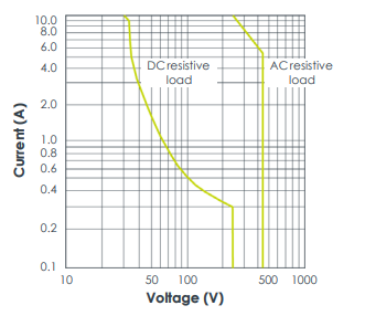
Maximum switching capacity curves :
Operate / release time : 7 / 3 ms typ.
Dielectric strength
• Between open contacts : 1000 VAC (RMS)
• Between contact and coil : 5000 VAC (RMS)
S
Insulation resistance : 1000 MΩ min. (at 500 VDC, 50% relative humidity (RH))
Mechanical life : >1 × 10⁷ operations
Electrical life : >1 × 10⁵ operations (at 8 A, 250 VAC)
When used in a VM600Mk2 slimline rack (ABE056) with a DC power supply, the relay contacts on an IOC4Mk2
module have a maximum switching voltage of 70 VDC / 33 VAC (RMS) (46.7 VAC (PEAK)).
Environmental
Temperature
• Operating : −20 to 65°C (−4 to 149°F)
• Storage : −40 to 85°C (−40 to 185°F)
Humidity
• Operating and storage : 0 to 95% relative humidity (RH), non-condensing
Altitude : 2000 m (6560 ft) max.
Note: Reduced air density affects cooling ability.
Approvals
Conformity : CE marking, European Union (EU) declaration of conformity
Electromagnetic compatibility : EN 61000-6-2:2005.
EN 61000-6-4:2007 + A1:2011.
Electrical safety : EN 61010-1:2010.
CAN/CSA-C22.2 No. 61010-1.
Environmental management : RoHS compliant (2011/65/EU)
Insulation coordination for measuring
relays and protection equipment
: Separate circuits according to IEC 60255-27
Note: Some certifications and approvals for the VM600Mk2 MPC4Mk2 + IOC4Mk2 modules are pending.
Power supply to module (input)
Power source : VM600Mk2 rack power supply
Supply voltages : +5 VDC and ±12 VDC
Consumption
• MPC4Mk2 : <6 W
• IOC4Mk2 : <9 W
Total power consumption
(set of MPC4Mk2/IOC4Mk2 modules)
: <15 W
Power supplies to sensors (output)
Number : 6 × independent sensor power supplies.
Note: One per input/channel (CH1 to CH4, AX1 and AX2).
Power supply output
• Constant voltage : +24 or −24 VDC ±3% at up to 35 mA max.
Note: Short-circuit protected.
• Constant current : +6 mA ±1%.
Note: Voltage compliance >22 VDC.
S
Control inputs
MPC4Mk2
• Button 1 (left) : Used to run the proof test for MPC4Mk2 + IOC4Mk2 modules
• Button 2 (right) : Used to lock/unlock MPC4Mk2 + IOC4Mk2 modules, that is, to switch
between the main operating modes of a VM600Mk2 system
(MPC4Mk2 + IOC4Mk2 modules and any associated RLC16Mk2
modules), as follows:
• Locked (secure operating mode) – the VM600Mk2 system
performs its monitoring and protection functions while ensuring
the security of the modules/system and it’s configuration. That is,
the configuration cannot be changed and maintenance activities
cannot be performed.
• Unlocked (maintenance operating mode) – the VM600Mk2
system performs its monitoring and protection functions without
ensuring the security of the modules/system and it’s configuration.
That is, the configuration can be changed and maintenance
activities can be performed.
Note: Physical access to a VM600Mk2 system (specifically, the
MPC4Mk2 module) is required in order to change the operating
mode and therefore to be able to change the machinery
protection (MPS) functionality for a VM600Mk2 system.
• Reset : Simultaneously pushing buttons 1 (left) and 2 (right) is used to reset
a set of MPC4Mk2 + IOC4Mk2 modules and any associated RLC16Mk2
modules (VM600Mk2 system), resulting in a reboot and power-on
self-test (POST)
IOC4Mk2
• DSI signals : See Discrete signal interface (DSI) inputs on page 10
Status indicators (LEDs)
MPC4Mk2
• DIAG/STATUS : Multicolour LED used to indicate the status of the
MPC4Mk2 + IOC4Mk2 modules, such as normal operation,
configuration status or internal hardware or firmware failures
• CH1 to CH4 : Multicolour LEDs used to indicate the status of the dynamic
channels (CH1 to CH4)
• AX1 and AX2 : Multicolour LEDs used to indicate the status of the auxiliary
channels (AX1 and AX2)
• Lock/Unlock : LED used to indicate the main operating mode of the
MPC4Mk2 + IOC4Mk2 modules (VM600Mk2 system):
Locked (safety operating mode) or
Unlocked (maintenance operating mode)
• LAN : Separate Link and Activity LEDs to indicate the status of system
LAN (Ethernet) communications
Connectors
MPC4Mk2
• CH1 to CH4 : BNC connectors (female).
Buffered “raw” sensor/measurement chain signals for the
dynamic channel inputs (CH1 to CH4).
Note: For the dynamic channels, the buffered “raw” outputs are
analog signals.
• AX1 and AX2 : BNC connectors (female).
Buffered “raw” sensor/measurement chain signals for the
auxiliary channel inputs (AX1 and AX2).
Note: For the auxiliary channels, the buffered “raw” outputs are
analog signals. Corresponding digital signals are available on J2.
• LAN : 8P8C (RJ45) modular jack, female.
System Ethernet for communication between the
MPC4Mk2 + IOC4Mk2 modules and a computer running the
VibroSight® software.
IOC4Mk2
• J1 : 24-pin S2L connector (male), compatible with 24-pin B2CF plug-in
connectors (female) with PUSH IN spring connections and B2L plugin connectors (female) with tension clamp spring connections.
Inputs (analog signals) for the dynamic channels (CH1 to CH4) and
the auxiliary channels (AX1 and AX2).
• J2 : 36-pin S2L connector (male), compatible with 36-pin B2CF plug-in
connectors (female) with PUSH IN spring connections and B2L plugin connectors (female) with tension clamp spring connections.
Outputs (buffered “raw” signals) for the dynamic channels (CH1 to
CH4) and the auxiliary channels (AX1 and AX2).
Outputs (digital (pulse train) signals (TTL-level)) for the auxiliary
channels (AX1 and AX2).
Inputs and ground reference (digital signals) for the DSI control
signals (AB, AR and TM).
Outputs (analog signals) for the analog DC outputs.
• J3 : 16-pin connector (male), compatible with 16-pin MC/STF plug-in
connectors (female) with screw-terminal connections.
Outputs (contacts) for the common circuit-fault relay (FAULT) and
the user-configurable relays (RL1 to RL4).
Notes
The connectors are removable to simplify installation and mounting.
There is 1 × COM, 1 × NC and 1 × NO contact available per user-configurable relay (RL1 to RL4).
There is 1 × COM, 1 × COM FUSED, 1 × NC and 1 × NO contact available per common circuit-fault relay
(FAULT).
SPECIFICATIONS (continued)
Physical
MPC4Mk2
• Height : 6U (262 mm, 10.3 in)
• Width : 20 mm (0.8 in)
• Depth : 187 mm (7.4 in)
• Weight : 0.42 kg (0.93 lb) approx.
IOC4Mk2
• Height : 6U (262 mm, 10.3 in)
• Width : 20 mm (0.8 in)
• Depth : 125 mm (4.9 in)
• Weight : 0.31 kg (0.68 lb) approx.
Meggitt (Meggitt PLC) is a leading international engineering company, headquartered in England, that designs and delivers high-performance
components and subsystems for aerospace, defence and selected energy markets. Meggitt comprises four customer-aligned divisions:
Airframe Systems, Engine Systems, Energy & Equipment and Services & Support.
The Energy & Equipment division includes the Energy Sensing and Controls product group that specialises in sensing and monitoring solutions for a
broad range of energy infrastructure, and control valves for industrial gas turbines, primarily for the Power Generation, Oil & Gas and Services markets.
Energy & Equipment is headquartered in Switzerland (Meggitt SA) and incorporates the vibro-meter® product line, which has over 65 years of sensor
and systems expertise and is trusted by original equipment manufacturers (OEMs) globally.
All information in this document, such as descriptions, specifications, drawings, recommendations and other statements, is believed to be
reliable and is stated in good faith as being approximately correct, but is not binding on Meggitt (Meggitt SA) unless expressly agreed in
writing. Before acquiring and/or using this product, you must evaluate it and determine if it is suitable for your intended application. You
should also check our website at www.meggittsensing.com/energy for any updates to data sheets, certificates, product drawings, user
manuals, service bulletins and/or other instructions affecting the product.
Unless otherwise expressly agreed in writing with Meggitt SA, you assume all risks and liability associated with use of the product. Any
recommendations and advice given without charge, whilst given in good faith, are not binding on Meggitt SA. Meggitt (Meggitt SA) takes
no responsibility for any statements related to the product which are not contained in a current Meggitt SA publication, nor for any
statements contained in extracts, summaries, translations or any other documents not authored and produced by Meggitt SA.
The certifications and warranties applicable to the products supplied by Meggitt SA are valid only for new products purchased directly from
Meggitt SA or from an authorised distributor of Meggitt SA.
In this publication, a dot (.) is used as the decimal separator and thousands are separated by thin spaces. Example: 12345.67890.
Copyright© 2020 Meggitt SA. All rights reserved. The information contained in this document is subject to change without prior notice.
-
 Jaquet Relay card (Auxiliary module) FTV 3090 377Z-03985
 -
 Jaquet Trip Chain Control card FTBU 3034 377Z-05030
 -
 Jaquet with input card -E04 FTFU 3024 -E04 377Z-05855
 -
 Jaquet with input card -E03 FTFU 3024- E03 377Z-03983
 -
 Jaquet FTFU 3024- E02 377Z-03982 with input card -E02
 -
 Jaquet FTFU 3024-E01 377Z-03981 with input card -E01
 -
 Hirschmann RS20-2400T1T1SDAE Industrial Managed Ethernet Switch
 -
 Hirschmann BELDEN EAGLE30-04022O6TT999SCCV9HSE3F
 -
 Hirschmann MM3-2FXS2/2TX MICE Media Module
 -
 Hirschmann RS20-1600M2M2SDAPHC08.0.05 Industrial Managed Switch
 -
 Hirschmann OZD Profi 12M G12-1300 PRO Fieldbus Repeater
 -
 Hirschmann SPIDER 4TX/1FX-ST EEC Industrial Ethernet Switch
 -
 Hirschmann MM2-2FXM3/2TX1 MICE Media Module
 -
 Hirschmann RS20-2400M2M2SDAPHC09.0.14 Industrial Switch
 -
 Hirschmann RS20-0400M2M2SDAEHC07.1.05 OpenRail Switch
 -
 Hirschmann OZD Profi 12M G12-EEC Fieldbus Repeater
 -
 HIRSCHMANN MDA422-1/2-3.5c-23/46 sensor
 -
Hirschmann RS30-2402T1T1SDAUHC Managed Industrial Switch
-
 Hirschmann OZD GENIUS G12 Industrial Switche
 -
 Hirschmann OZD 485 G12-1300 PRO Fieldbus Repeater
 -
 Hirschmann MM2-2FXM2 MICE Media Module
 -
 Hirschmann RS20-1600S2T1SDAUHC Managed Industrial Switch
 -
 Hirschmann MS20-0800SAAEHH04.2.04 MICE Switch
 -
 Hirschmann SPIDER 4TX/1FX EEC Unmanaged Industrial Switch
 -
 HIRSCHMANN MS4128-L3P EEC Managed Industrial Ethernet Switch
 -
 HIRSCHMANN RS20-0400M2T1SDAPHC08.0.01 Managed Switch
 -
 ETEL EA-S0M-400-40/80A-0000-00 AccurET Modular Power Supply
 -
 ETEL EA-B0I-0-0-0000-00 Backplane Interface Board
 -
 ETEL EA-P2M-400-15/40A-0100-00 Position Controller
 -
ETEL EA-P2M-400-15/40A-0000-00 Position Controller
-
 ETEL EA-P2M-400-10/20A-0100-01 Position Controller
 -
 ETEL EA-P2M-400-10/20A-0000-01 Position Controller
 -
 ETEL EA-P2M-400-5/10A-0100-01 Position Controller
 -
 ETEL EA-P2M-048-2.5/5A-0000-01 Modular Position Controller
 -
 ETEL EA-S0M-300-40/80A-0000-00 Power Supply Module
 -
 ETEL EA-P2M-300-07/15A-0100-01 Position Controller
 -
 ETEL EA-P2M-300-07/15A-0000-01: Modular Position Controller
 -
 ETEL EA-P2M-300-4/7.5A-0100-01 Overview
 -
 Basler Electric MOC2. Motor Operated Potentiometer
 -
 Basler Electric BE1-11 RTD Module, Resistance Temperature Detector
 -
 Basler Electric RDP-110C, Remote Display Panel
 -
 Basler Electric VRM-2020. Voltage Regulation Module
 -
 Basler Electric IDP-1500. Interactive Display Panel
 -
 Basler Electric AEM-2020. Analog Expansion Module
 -
 Basler Electric IDP-2020. Interactive Display Panel
 -
 Basler Electric CEM-2020. Contact Expansion Module
 -
 Basler Electric CEM-125. Contact Expansion Module
 -
 Basler Electric BE2000E, Digital Voltage Regulator
 -
 Basler Electric SMC-150. Synchronous Motor Controller
 -
 Basler Electric AVC125-10. Voltage Regulator
 -
 Basler Electric BE1-25. Sync-Check Relay
 -
 Basler Electric DGC-2020ES, Digital Genset Controller
 -
 ETEL EA-P2M-400-5/10A-0000-01 Position Controller
 -
 Basler Electric BE1-64F, Ground Fault Relay
 -
 Basler Electric BE1-79M, Multi Shot Reclosing Relay
 -
 Basler Electric BE1-81O/U, Digital Frequency Relay
 -
 Basler Electric BE1-87B, High Impedance Bus Differential Relay
 -
 Basler Electric BE1-79A, Reclosing Relay
 -
 Basler Electric BE1-27. BE1-59. BE1-27/59. Voltage Relay
 -
 Basler Electric SMC-250. Synchronous Motor Controller
 -
 Basler Electric SGC-250N, Synchronous Generator Controller
 -
 Basler Electric SGC-250. Synchronous Generator Controller
 -
 Basler Electric BE1-50/51 Plug and Play and Retrofit Relays
 -
 Basler Electric DECS-2100. Digital Excitation Control System
 -
 Basler Electric DECS-250E, Digital Excitation Control System
 -
 Basler Electric BE1-700V, Voltage Only Digital Protective Relay
 -
 Basler Electric DECS-250. Digital Excitation Control System
 -
 Basler Electric DECS-450. Digital Excitation Control System
 -
 Basler Electric DECS-150. Digital Excitation Control System
 -
 Basler Electric ES-49. Temperature Relay
 -
 Basler Electric ES-81O/U, ES-81O,ES-81U Overfrequency Relay
 -
Basler Electric ES-74V, DC Voltage Sensing Relay
-
Basler Electric ES-27/59. Under/Overvoltage Relay
-
 Basler Electric ES-27. Undervoltage Relay
 -
 Basler Electric ES-25. Sync-Check Relay
 -
 Basler Electric ES-47, ES-47N Phase Sequence Relay
 -
Basler Electric ES-37.ES-37/51 Undercurrent Relay
-
 Basler Electric ES-32. Reverse Power Relay
 -
Basler Electric ES-59. Overvoltage Relay
-
 Basler Electric ES-55. Power Factor Relay
 -
 Basler Electric DGC-2020HD, Digital Genset Controller
 -
 Basler Electric BE1-FLEX, Protection, Automation, and Control System
 -
 Schneider GUTOR OC0935 Power Factor Sampling Board
 -
 Schneider GUTOR OC0922 Analog Signal Isolation Board
 -
 Schneider GUTOR OC0908 Battery Voltage Detection Board
 -
Schneider GUTOR OC0947 Temperature / IGBT Sampling Board
-
 Schneider GUTOR OP2601 Communication Expansion Board
 -
 Schneider Electric GUTOR OP2312 bypass control board
 -
 Schneider Electric GUTOR OP2130 Cooling Fan Monitoring & Control Board
 -
 Schneider Electric GUTOR OP2010 Battery Test Board / Battery Management Diagnostic Card
 -
Schneider Electric GUTOR OP2552 Three-phase Power Connection Board Assembly
-
 Schneider Electric GUTOR OP1922A Parallel Control Board / Load-Sharing Synchronization Module
 -
 Schneider Electric GUTOR OP6290B Inverter Feedback Acquisition Board / Signal Scaling Module
 -
Schneider GUTOR OP6280 Basic Signal Board
-
Schneider Electric GUTOR OP2456 / OP2456B Main control board
-
 Schneider Electric GUTOR OP2452 Power Plug-in Panel
 -
 Schneider Electric GUTOR OP2450 Parallel Communication Board
 -
Schneider Electric GUTOR OP2406 Interface Fuse Monitoring Board
-
 Schneider Electric GUTOR OC0919 High-Power Semiconductor Module
 -
 Schneider Electric GUTOR OP6281A System Logic Interface Board
 -
 Schneider Electric GUTOR OP6285A Power Signal Acquisition Board
 -
 Schneider Electric GUTOR OP2438 Fan Monitor & Drive Protection Board
 -
Schneider Electric GUTOR OP2446 Main Control CPU Board
-
 ROLLS-ROYCE CE05-00 Steering Gear Control Module
 -
 ROLLS-ROYCE MARINE AS-BRATTVAAG WRC1021A CONTROLLER CARD
 -
ROLLS ROYCE DECK MACHINERY MPC-300-A7029099 TERMINAL CONTROLLER UNIT
-
 ROLLS-ROYCE HELICON THRUSTER CONTROL PANEL LF90S-01-06
 -
 Rolls-Royce PCC1030C Panel Controller Card
 -
 Rolls-Royce RRDIO15 Remote Digital Input/Output Module
 -
 Rolls-Royce TDI-11 Pitch & Direction Indicator Module
 -
 Rolls-Royce CCN 01 CANman Controller Network Module
 -
 Rolls-Royce SLIO 01 CANman Controller Network Module
 -
 Rolls-Royce MPC-210 Winch & Propulsion Control Module
 -
Rolls-Royce MTI-144 Engine Control Module
-
 Rolls-Royce Tenfjord FB10-002 Steering Gear Module (E-4500-40-1)
 -
 ROLLS ROYCE MARINE AS CIRCUIT BOARD (PCB) RRAI016
 -
 Rolls-Royce Marine AS PIP6-1 Marine Controller
 -
 ROLLS-ROYCE MPC-300 STARTER CONTROL UNIT A7029099
 -
 Rolls-Royce Data Respons MPCF1-10.4" Maritime Panel Computer
 -
 ROLLS-ROYCE MARINE OLC-40009 PCB CARD
 -
Rolls-Royce Marine Brattvaag WRC1021B Controller Board
-
 ROLLS-ROYCE CCN 01 & ROLLS-ROYCE SLIO 02 CANMAN CONTROLLER NETWORK
 -
.png) ROLLS-ROYCE ATC-3-A7033172 AQUAMASTER TURNING CONTROLLER
ROLLS-ROYCE ATC-3-A7033172 AQUAMASTER TURNING CONTROLLER -
 ROLLS-ROYCE POSCON V.3 JOYSTICK MODULE 6459
 -
.png) Rolls-Royce Marine 389-496-00 Joystick Remote Control Panel 6799-W, 389-996-00
Rolls-Royce Marine 389-496-00 Joystick Remote Control Panel 6799-W, 389-996-00 -
 Rolls-Royce data respons 10.4'' Panel Computer 98H010A0000I/R10I53S
 -
 Rolls-Royce H1127.0101 Marine Controller 000068308
 -
 Rolls-Royce CU40-0106-50 Steering Gear Control Panel


