
Product Description of F3236 Digital Input Module
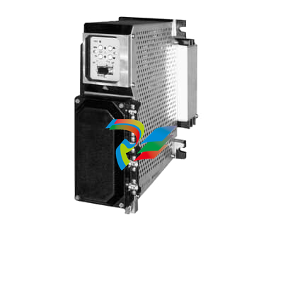
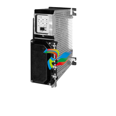
The F3236 Digital Input Module is a high-reliability industrial I/O component designed for precise and real-time monitoring of digital signals in critical automation and safety systems. As a key part of industrial control architectures, this module converts external digital signals (such as status signals from sensors, switches, or actuators) into processable data for controllers, enabling accurate status detection and rapid response in complex industrial environments.
Core Functions and Features
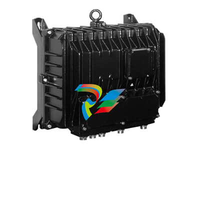
High-Speed Signal Acquisition: The F3236 module supports high-frequency digital signal sampling, ensuring real-time capture of on/off status changes from field devices. With minimal input delay, it guarantees timely data transmission to the controller, critical for time-sensitive safety and control logic.
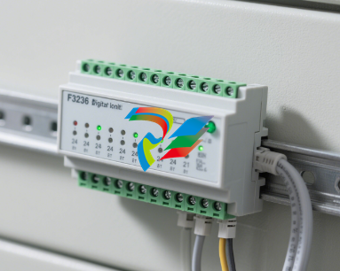
# F3236 Digital Input Module User Manual ## 1. Overview The F3236 Digital Input Module is a high-performance industrial control component designed to collect and transmit digital signals in automated systems. It features stable operation, high anti-interference capability, and flexible configuration, making it suitable for various industrial environments such as manufacturing, power, and transportation. ## 3. Installation Instructions ### 3.1 Mounting - The module should be installed on a standard DIN rail (35mm) in a control cabinet. - Ensure adequate ventilation around the module to prevent overheating; maintain a minimum distance of 50mm from heat sources. - Tighten the mounting clips securely to avoid vibration-induced loosening. ### 3.2 Wiring - **Power Supply**: Connect the DC 24V power supply to the terminals marked "V+" (positive) and "V-" (negative). Reverse polarity protection is included, but incorrect wiring may cause temporary malfunction. - **Digital Inputs**: Connect external devices (e.g., sensors, switches) to the input terminals (CH1-CH16). For dry contact inputs, connect the common terminal (COM) to one side of the contact and the channel terminal to the other. For voltage inputs, ensure the signal matches the input range. - **Communication**: Use shielded twisted-pair cable for RS485 communication. Connect A (positive) and B (negative) terminals to the corresponding bus lines; ground the shield at one end to reduce interference. ## 4. Operation Guide ### 4.1 Power-On Check - After wiring, verify all connections are correct before powering on. - The power indicator (PWR) will illuminate green when the module is powered on normally. - Input status indicators (CH1-CH16) will light up red when a high-level signal (or closed contact) is detected. ### 4.2 Parameter Configuration - Configure communication parameters (baud rate, parity, address) via Modbus RTU commands using a configuration tool or PLC. Default settings: Baud rate = 9600, Parity = None, Address = 1. - Adjust input filter time if needed (default: 1ms) to suppress noise; longer filter times reduce response speed. ### 4.3 Data Reading - Read input status via Modbus function code 0x02 (Read Discrete Inputs). The module returns a 16-bit data frame, where each bit corresponds to an input channel (1 = active, 0 = inactive). ## 6. Maintenance and Safety - Regularly inspect wiring terminals for corrosion or loosening; clean with a dry cloth if necessary. - Avoid exposure to dust, moisture, or corrosive gases; use a protective enclosure in harsh environments. - Disconnect power before performing maintenance or wiring modifications to prevent electric shock. ## 7. Warranty The F3236 Digital Input Module comes with a 2-year warranty from the date of purchase. Warranty does not cover damage caused by improper installation, wiring errors, or unauthorized modification. **Note**: For further technical support, contact our service team at support@example.com. *Document Version: V1.0 | Date: 2025-08-18*
| User name | Member Level | Quantity | Specification | Purchase Date |
|---|


-
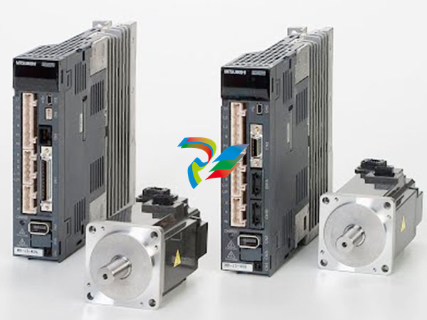
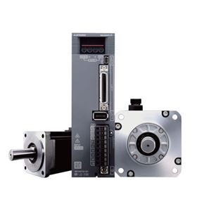
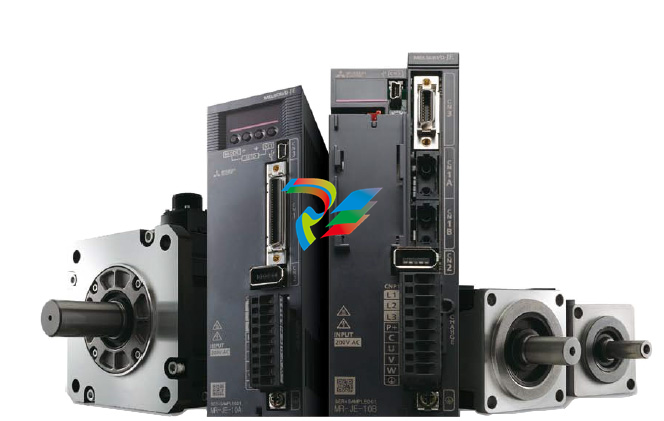
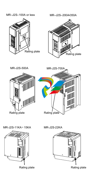 Mitsubishi MELSERVO-J2-Super series general-purpose AC servo
 -
 Mitsubishi MELSERVO-J3 servo system
 -
 Mitsubishi MELSERVO-JE servo system
 -
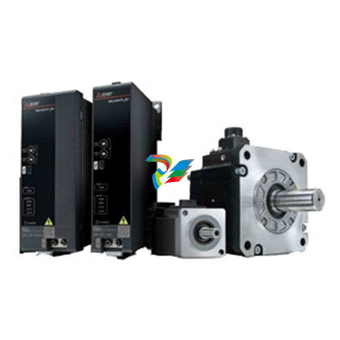
 Mitsubishi MELSERVO-J4 AC servo
 -
 Mitsubishi MELSERVO-JET servo system
 -
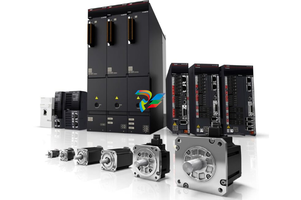 Mitsubishi MELSERVO-J5 AC servo
 -
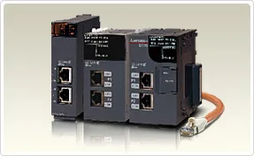 Mitsubishi Melsec-related network products
 -
 Mitsubishi MELSEC-QS/WS series
 -
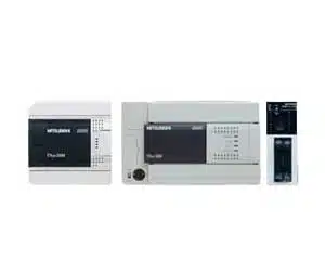 Mitsubishi MELSEC-F series
 -
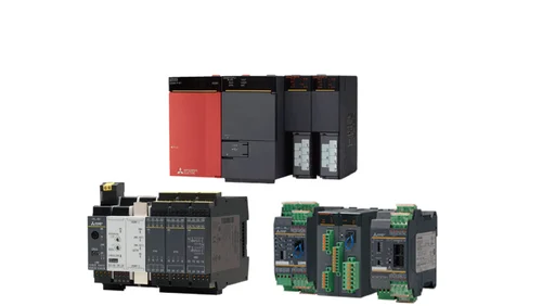
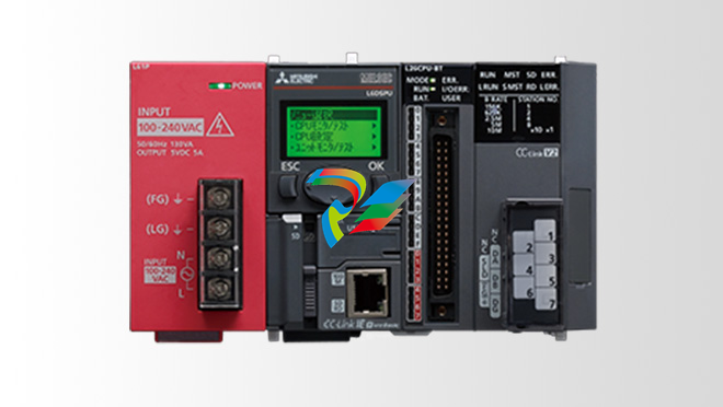 Mitsubishi MELSEC-L series
 -
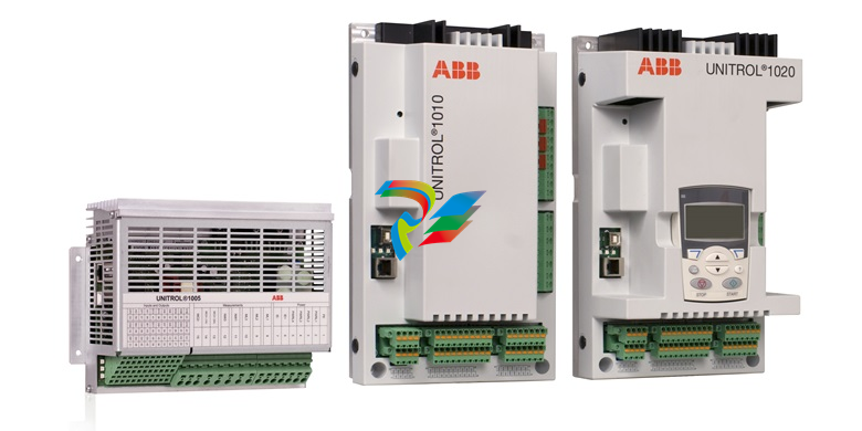
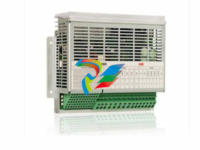 ABB UNITROL 1005 Automatic voltage regulator
 -
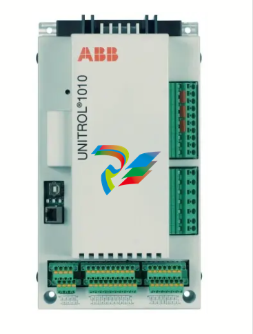 ABB UNITROL 1010 medium synchronous generators and industrial machines
 -
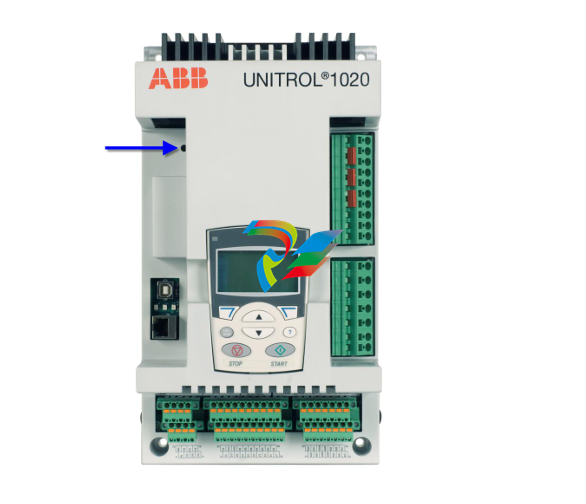 ABB UNITROL 1020 Synchronous voltage regulator
 -
 UNITROL 1000 Automatic voltage regulators (AVR)
 -
 Bently Nevada 3500/65 145988-02 temperature monitor
 -
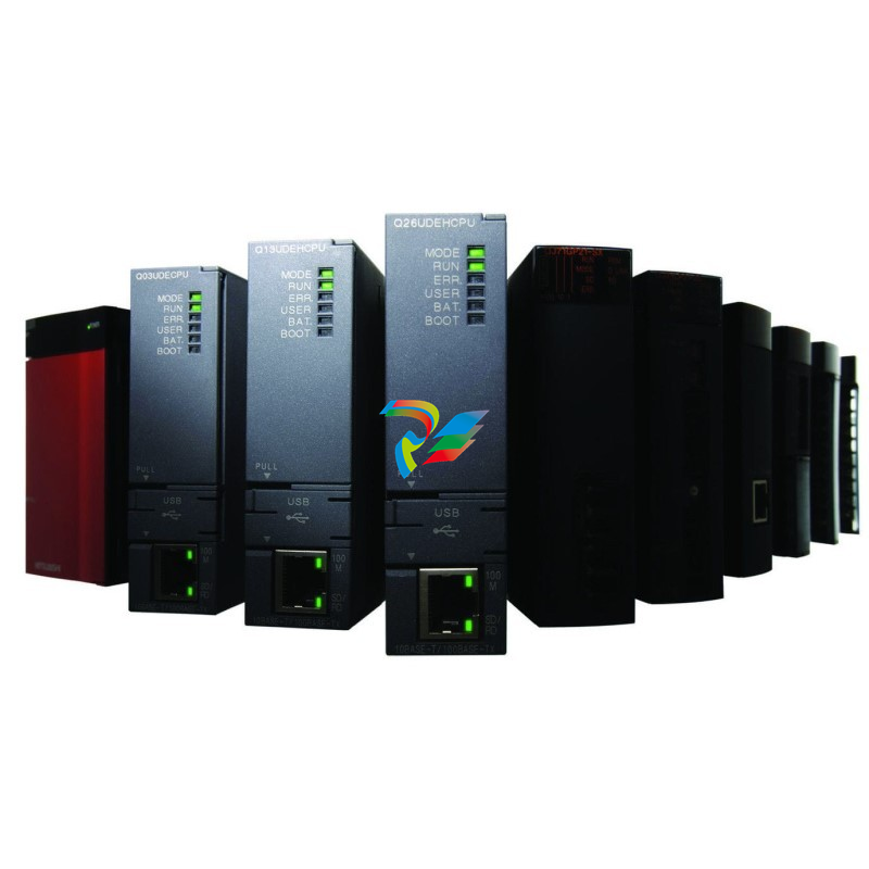 Mitsubishi MELSEC-Q series
 -
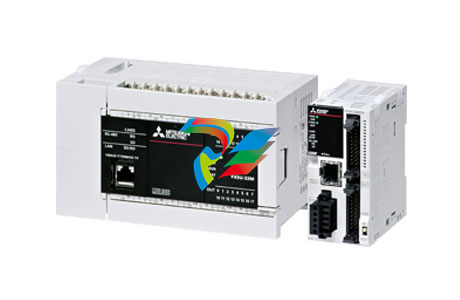 Mitsubishi MELSEC iQ-F series
 -
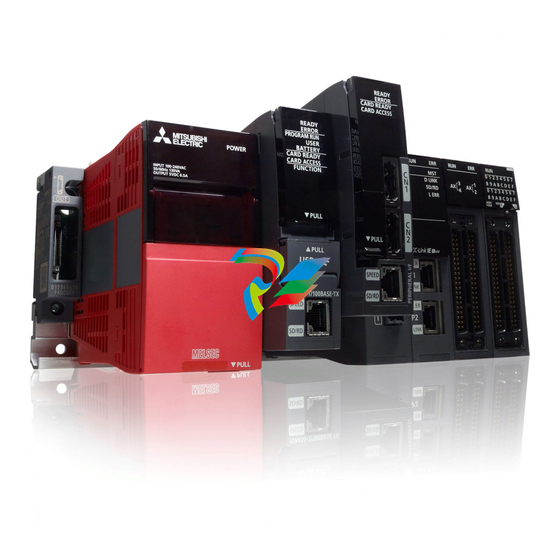 Mitsubishi MELSEC iQ-R series
 -
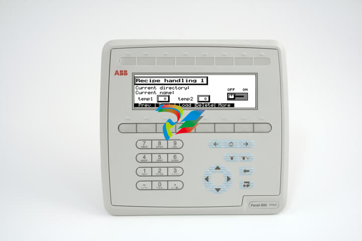 ABB IndustrialIT Panel 800 - PP820
 -
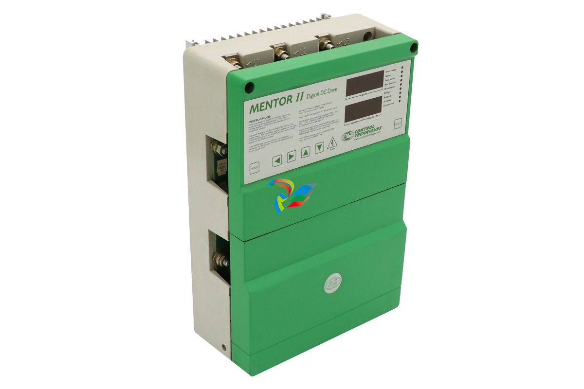 MENTOR II M25RGB14 Controller
 -
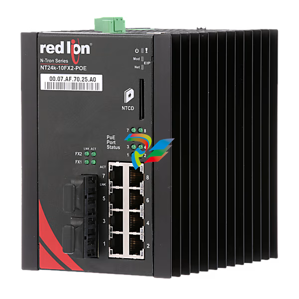 N-Tron® NT24K-10FX2-SC-POE Managed 10-Port Industrial Ethernet Switch
 -
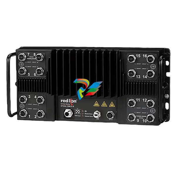 N-Tron® NT24K-16M12-POE-PT Managed 16-Port IP67 Gigabit Industrial Ethernet Switch
 -
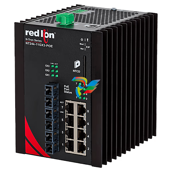 N-Tron® NT24K-11GX3-SC-POE Managed 11-Port Gigabit Industrial Ethernet Switch
 -
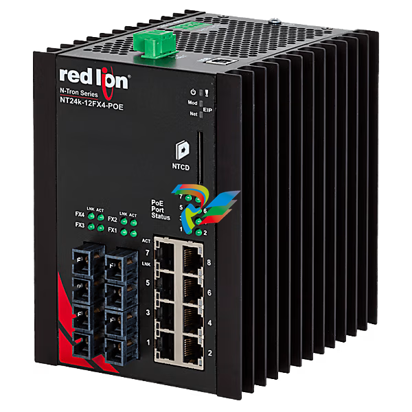 N-Tron® NT24K-12FX4-ST-POE Managed 12-Port Gigabit Industrial Ethernet Switch
 -
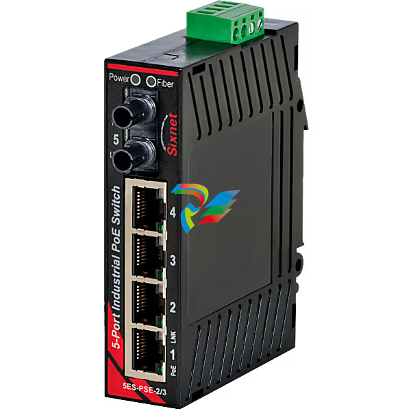
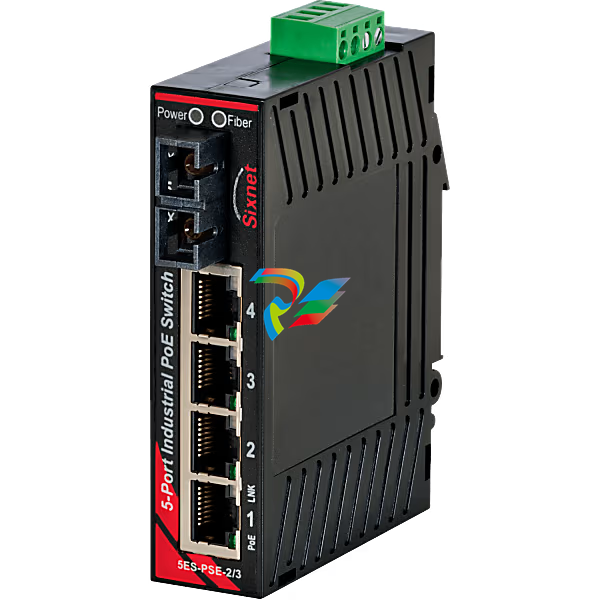
 Sixnet® EB-5ES-PSE-2SC Unmanaged 5-port PoE Industrial Switch
 -
 NT24k® 10FX2-POE Managed PoE+ Gigabit Ethernet Switch
 -
N-Tron® NT24K-16M12-POE-R-PT Managed 16-Port IP67 Gigabit Industrial Ethernet Switch
-
 N-Tron® NT24K-8TX-POE-PT Managed 8-Port Gigabit Industrial Ethernet Switch
 -
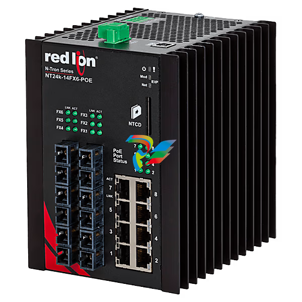 N-Tron® NT24K-14FX6-ST-POE Managed 14-Port Gigabit Industrial Ethernet Switch
 -
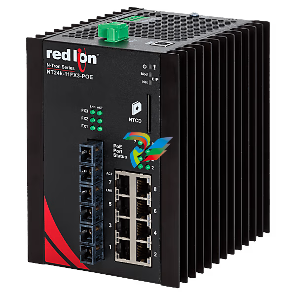 N-Tron® NT24K-11FX3-ST-POE Managed 11-Port Gigabit Industrial Ethernet Switch
 -
 N-Tron® 105FXE-ST-40-POE-MDR Unmanaged 5-port PoE Switch
 -
 Sixnet® EB-5ES Unmanaged 5-port PoE Industrial Switch, ST 60km
 -
 N-Tron® 100-POE4-MDR Industrial Midspan Injector, Metal DIN Rail
 -
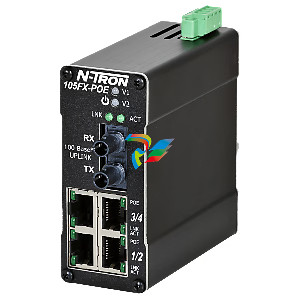
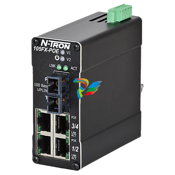
 N-Tron® 105FX-ST-POE Unmanaged 5-port PoE Switch
 -
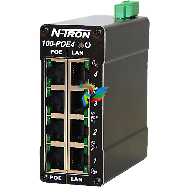
N-Tron® 100-POE4 Industrial Midspan Injector
-
N-Tron® NT24K-16M12-POE Managed 16-Port IP67 Gigabit Industrial Ethernet Switch
-
 N-Tron® 105FX-ST-POE-MDR Unmanaged 5-port PoE Switch
 -
 N-Tron® 105FXE-ST-15-POE Unmanaged 5-port PoE Switch
 -
Sixnet® EB-5ES-PSE-3ST Unmanaged 5-port PoE Industrial Switch
-
 N-Tron® 105FX-SC-POE Unmanaged 5-port PoE Switch
 -
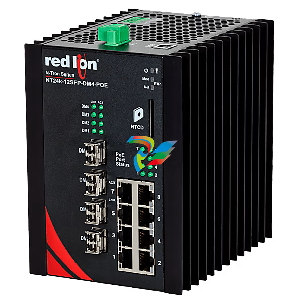 N-Tron® NT24K-12SFP-DM4-POE Managed 12-Port Gigabit Industrial Ethernet Switch
 -
N-Tron® NT24K-12FX4-SC-POE Managed 12-Port Gigabit Industrial Ethernet Switch
-
 N-Tron® 105FXE-ST-80-POE-MDR Unmanaged 5-port PoE Switch
 -
N-Tron® NT24K-14FX6-SC-POE Managed 14-Port Gigabit Industrial Ethernet Switch
-
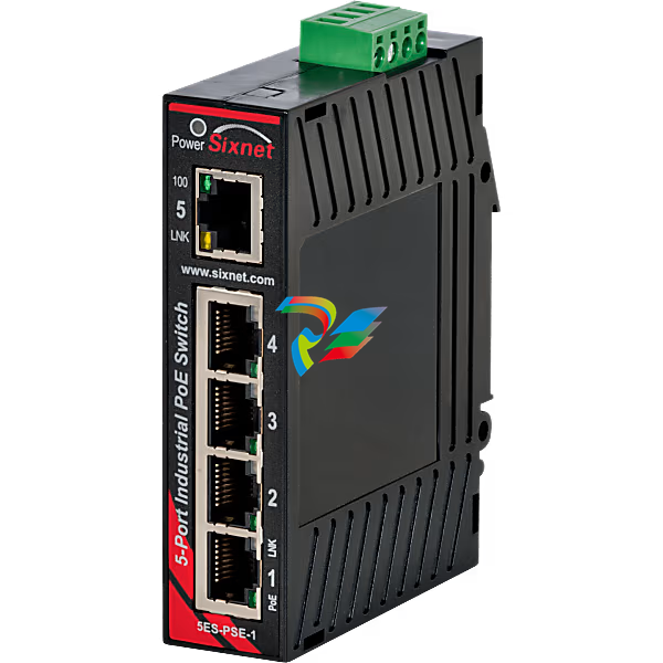
Sixnet® EB-5ES-PSE-1 Unmanaged 5-port PoE Industrial Switch
-
N-Tron® NT24K-16M12-POE-R Managed 16-Port IP67 Gigabit Industrial Ethernet Switch
-
N-Tron® NT24K-11FX3-SC-POE Managed 11-Port Gigabit Industrial Ethernet Switch
-
 N-Tron® 105FXE-SC-15-POE Unmanaged 5-port PoE Switch
 -
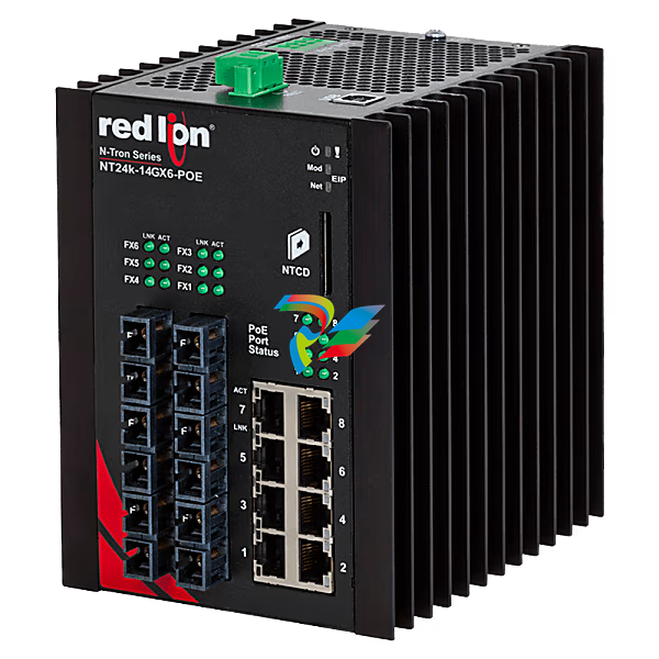 N-Tron® NT24K-14GX6-SC-POE Managed 14-Port Gigabit Industrial Ethernet Switch
 -
 N-Tron® 105FXE-SC-80-POE Unmanaged 5-port PoE Switch
 -
 N-Tron® 105FXE-SC-40-POE-MDR Unmanaged 5-port PoE Switch
 -
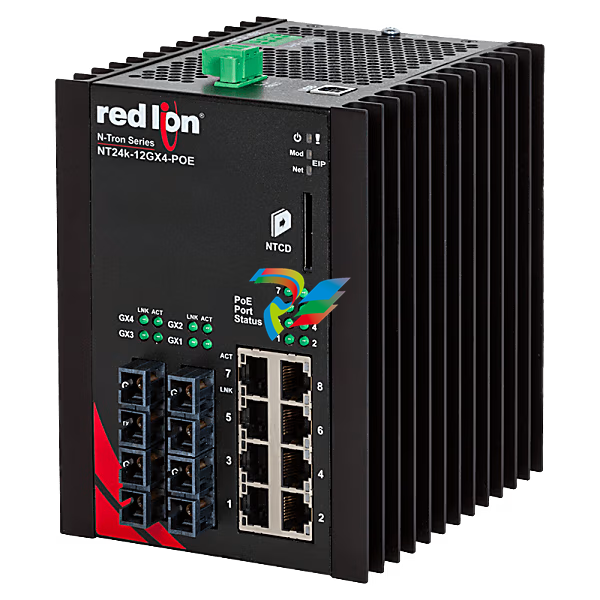 N-Tron® NT24K-12GX4-SC-POE Managed 12-Port Gigabit Industrial Ethernet Switch
 -
 Sixnet® EB-5ES Unmanaged 5-port PoE Industrial Switch, SC 20km
 -
 N-Tron® 105FXE-ST-15-POE-MDR Unmanaged 5-port PoE Switch
 -
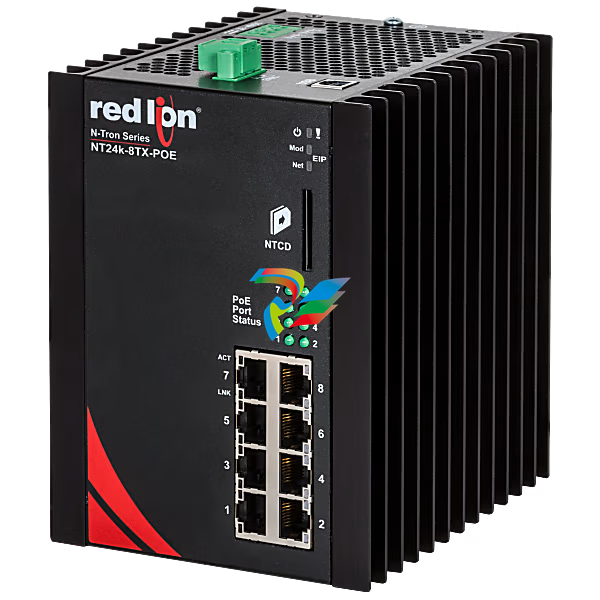 N-Tron® NT24K-8TX-POE Managed 8-Port Gigabit Industrial Ethernet Switch
 -
 N-Tron® 105FX-SC-POE-MDR Unmanaged 5-port PoE Switch
 -
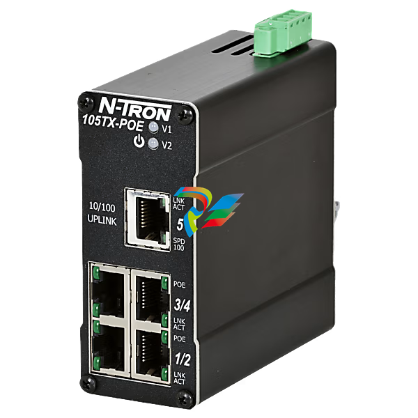
 N-Tron® 105TX-POE Unmanaged 5-port PoE Switch
 -
 Sixnet® EB-5ES Unmanaged 5-port PoE Industrial Switch, SC 60km
 -
 N-Tron® 105FXE-SC-15-POE-MDR Unmanaged 5-port PoE Switch
 -
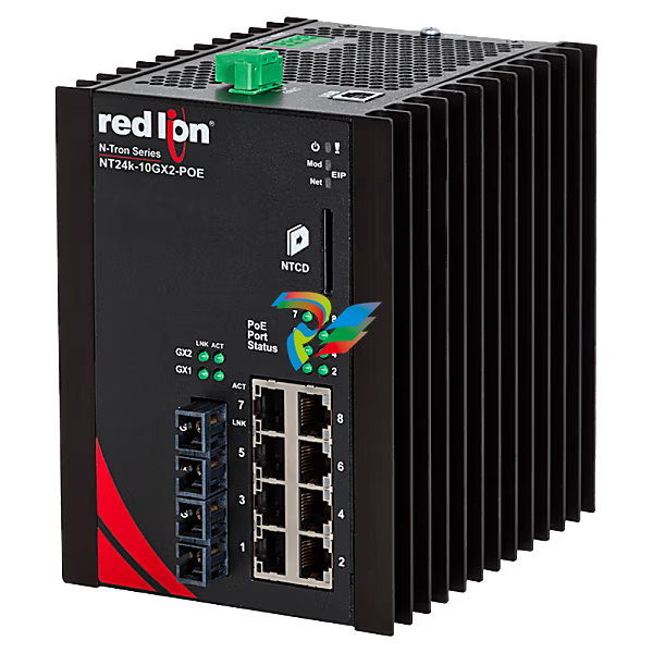 N-Tron® NT24K-10GX2-SC-POE Managed 10-Port Gigabit Industrial Ethernet Switch
 -
 N-Tron® 105TX-POE-MDR Unmanaged 5-port PoE Switch
 -
 N-Tron® 105FXE-ST-80-POE Unmanaged 5-port PoE Switch
 -
 N-Tron® 105FXE-SC-80-POE-MDR Unmanaged 5-port PoE Switch
 -
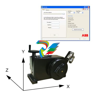 ABB Electrical actuators accessories ECOM700
 -
 Electronic unit EBS862 ABB
 -
ABB Electronic unit EBS852
-
 Electronic unit EAS822 ABB
 -
 Electronics EBN861 ABB
 -
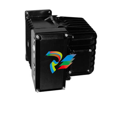 ABB Electronic unit EBN853
 -
 Electronic unit EAN823 ABB
 -
 Electrical linear actuator RSD100 (Contrac)
 -
 Electrical linear actuator RSD50 (Contrac)
 -
 ABB Electrical linear actuator RSD20 (Contrac)
 -
Electrical linear actuator RSD10 (Contrac)
-
 Linear actuator LME620-AI/-AN (Contrac)
 -
 abb Electrical rotary actuator RHD16000 (Contrac)
 -
ABB Electrical rotary actuator RHD8000 (Contrac)
-
 Electrical rotary actuator RHD4000 (Contrac)
 -
Electrical rotary actuator RHD1250 / RHD2500 (Contrac)
-
 Electrical rotary actuator RHD500 / RHD800 (Contrac)
 -
 Electrical rotary actuator RHD250 (Contrac)
 -
Rotary actuator PME120-AI/-AN (Contrac)
-
 I/P converters TEIP11 / TEIP11-PS
 -
 Digital positioner TZIDC-220 ABB
 -
 Digital positioner TZIDC-210 ABB
 -
 ABB Digital positioner TZIDC-200
 -
 Digital positioner TZIDC-120 ABB
 -
 Digital positioner TZIDC-110 ABB
 -
Digital positioner TZIDC ABB
-
 Digital positioner PositionMaster EDP300 ABB
 -
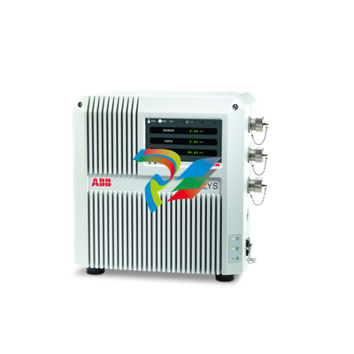 TALYS ADP300 series Dual channel wet process analyzer
 -
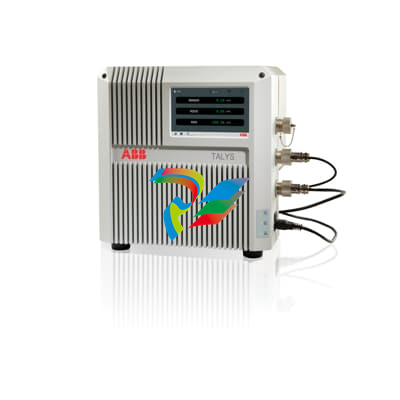
 FT-NIR analyzer TALYS ASP400 series ABB
 -
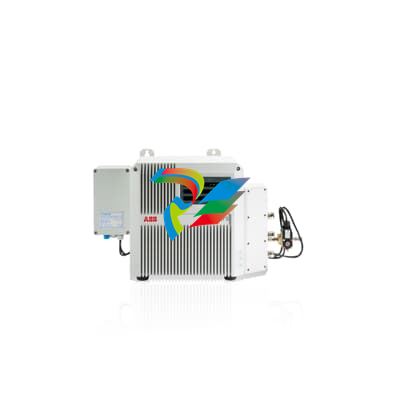
 Wet bath monitoring analyzer TALYS ASP300 series
 -
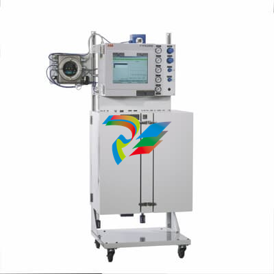 ABB FTPA2000-HP460 FT-NIR process analyzer
 -
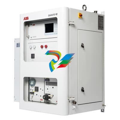 FT-NIR process analyzer for hydrocarbon FTPA2000-HP360
 -
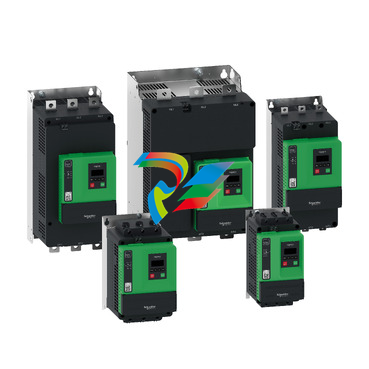 Altivar Soft Starter ATS430
 -
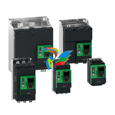 Altivar Soft Starter ATS490
 -
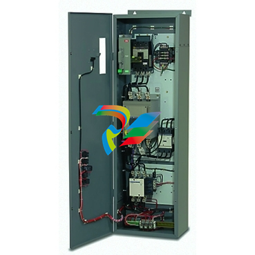 Soft Start - ATS48 Enclosed From 3HP to 600HP-
 -
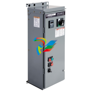 Soft Start - ATS22 Enclosed From 3HP to 500HP
 -
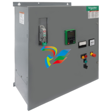 Altivar ATS480 Enclosed Soft Starter System
 -
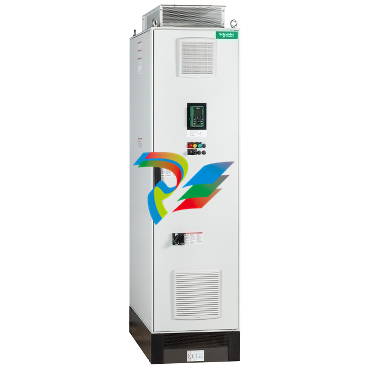 Altivar Process 680 AFE Low Harmonic Drive
 -
 Altivar Process 660 Drive System
 -
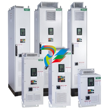
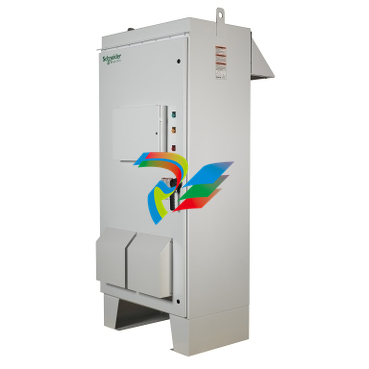 Altivar Outdoor Drive Utilizing the ATV 630/930 Process Drives
 -
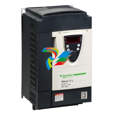 Altivar 71 Variable Frequency Drives VFD
 -
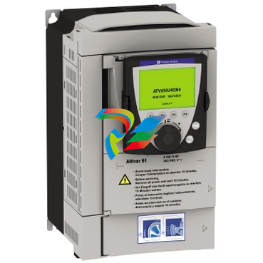 Altivar 61 Variable Frequency Drives VFD
 -
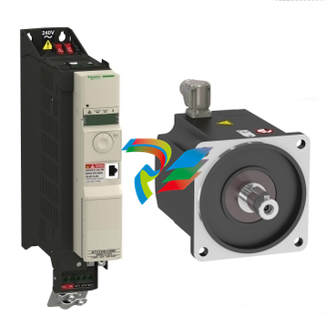 Altivar 32 Variable Frequency Drive VFD
 -
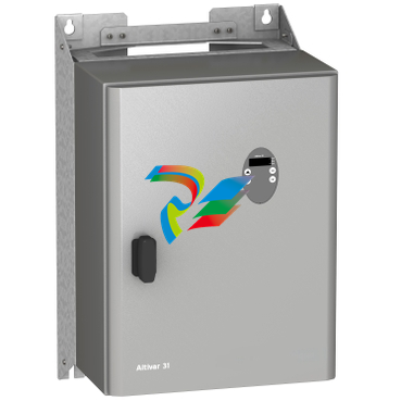 Altivar 31C Variable Frequency Drive VFD
 -
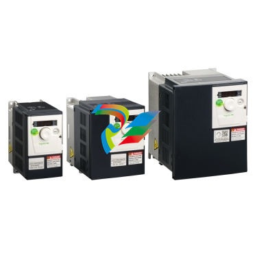 Altivar 312 Variable Frequency Drives VFD
 -
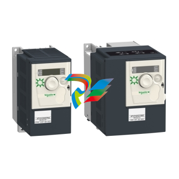 Altivar 312 Solar Variable speed drives for pumps with photovoltaic arrays
 -
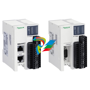 Modicon OTB IP20 optimum modular I/O system
 -
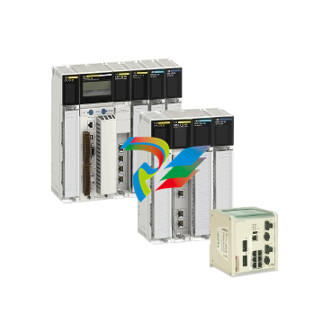 Schneider Modicon Quantum PAC
 -
 Schneider Modicon ABE9
 -
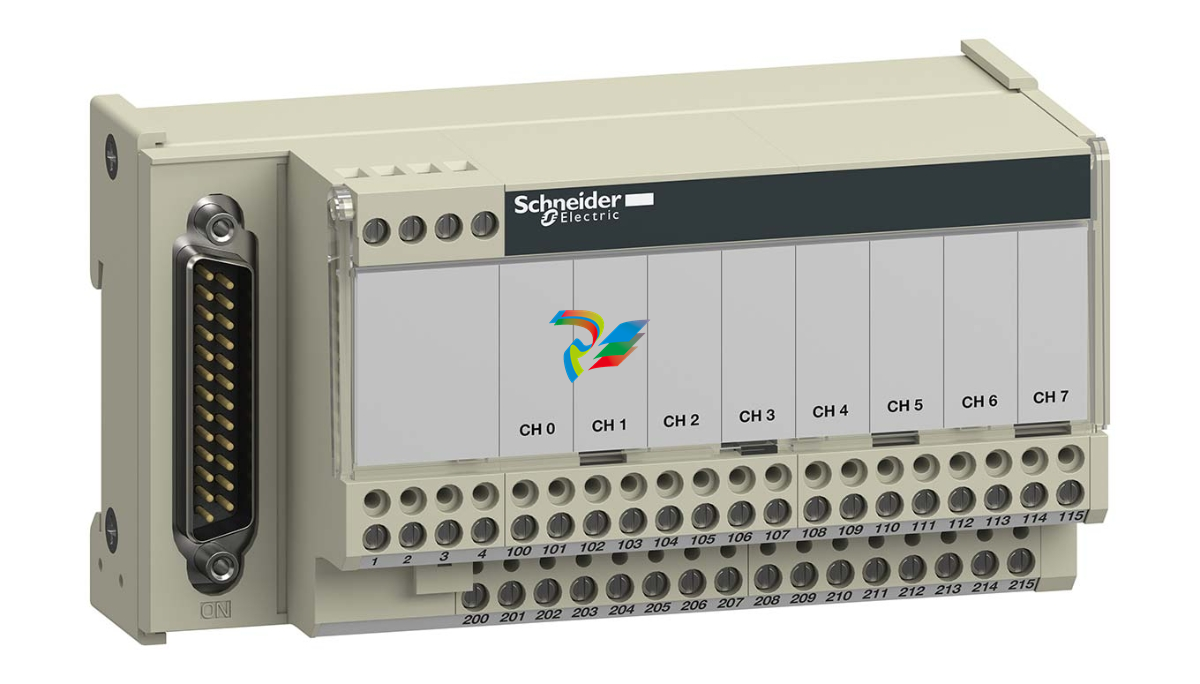 Schneider Advantys Telefast ABE 7
 -
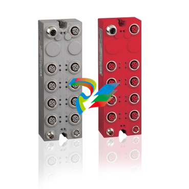 Modicon TM7 Remote I/O for Harsh Environments
 -
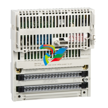 Modicon Momentum
 -
 Modicon STB IP20 modular distributed I/O
 -
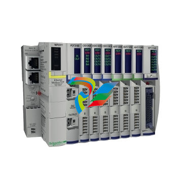
 Modicon TM5 IP20 Modular I/O System
 -
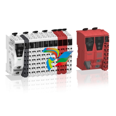
 Modicon Edge I/O NTS
 -
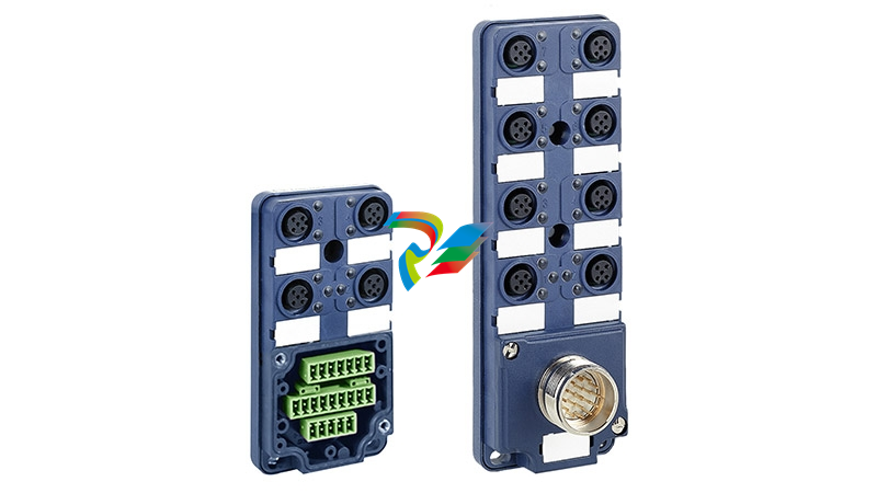
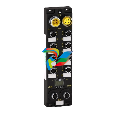 Modicon ETB IP 67 modular distributed I/O for Ethernet
 -
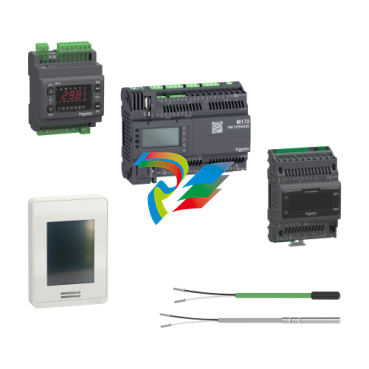 Modicon M171/M172 Logic Controller
 -
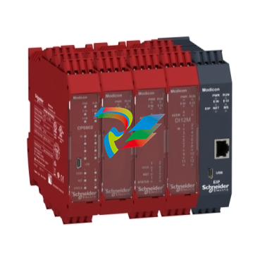 Modicon MCM Safety controllers
 -
 EcoStruxure™ OPC UA Server Expert
 -
 Modicon MC80 Compact Process Automation Controller
 -
Modicon M340 PAC
-
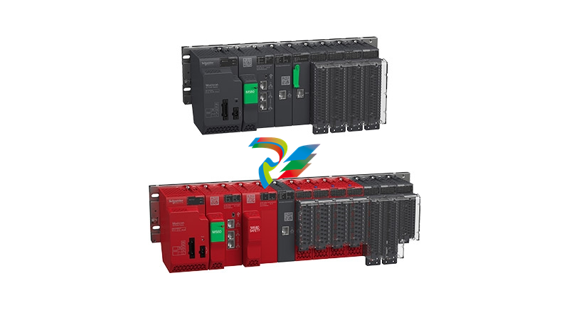 Modicon M580 PAC Controller
 -
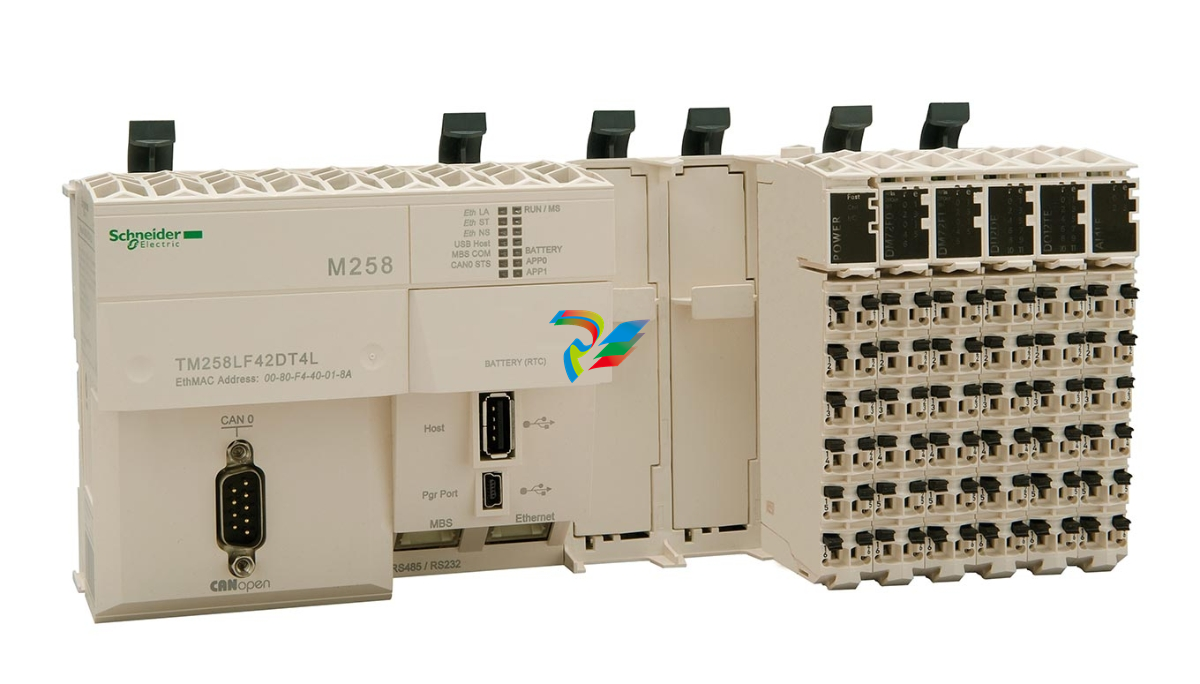 Modicon M258 Compact PLC for Machine Automation
 -
 Schneider Logic/Motion controller Modicon M262
 -
 Modicon M251 Micro PLC with Dual Channel Comm Schneider

