
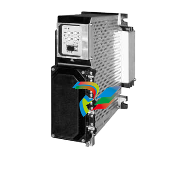
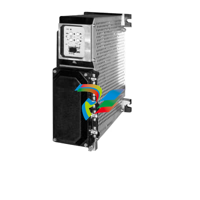
Basic Information: Branded as HIMA, it belongs to the HIQUAD series with model number F8627X, and is manufactured in Germany.
Interface Types: Equipped with multiple interfaces such as Ethernet (100BASE-TX), RS-232, RS-485, and CAN bus.
Communication Protocols: Supports various industrial standard protocols including Modbus, Profibus, Profinet, EtherNet/IP, TCP/IP, UDP, and Modbus TCP.
Data Transmission Rate: The Ethernet interface offers a data transmission rate of up to 100 Mbps.
Power Requirements: Operates on a DC power supply with a voltage of 24V.
Operating Environment: The operating temperature range is -40°C to +70°C, the storage temperature range is -40°C to +85°C, and the relative humidity is 5% to 95% (non-condensing).
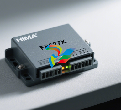
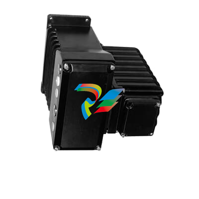
# User Manual for HIMA Communication Module F8627X
## 1. General Description
The HIMA F8627X is a high-reliability communication module designed for industrial automation and safety instrumented systems (SIS). It enables seamless data exchange between HIMA safety controllers, peripheral devices, and external systems, ensuring real-time communication with high integrity and fault tolerance. This module complies with international safety standards such as IEC 61508, making it suitable for critical applications in industries like oil & gas, chemical processing, and power generation.
## 3. Installation Instructions
### 3.1 Pre-Installation Checks
- Ensure the power supply voltage matches the module’s requirement (24V DC ±10%).
- Verify that the installation environment meets the temperature and humidity specifications (-40°C to +70°C, <95% RH non-condensing).
- Inspect the module for physical damage before installation.
### 3.2 Mounting Steps
1. Secure the 35mm standard DIN rail to the cabinet or mounting surface.
2. Align the module’s DIN rail clips with the rail and slide the module into place until it locks securely.
3. Ensure there is at least 10mm of clearance between the module and adjacent devices for heat dissipation.
### 3.3 Wiring Connections
- **Power Supply**: Connect the 24V DC positive (+) wire to terminal "V+" and the negative (-) wire to terminal "V-".
- **Profibus DP**: Use shielded twisted-pair cable to connect the Profibus network to terminals "A" (signal) and "B" (signal return). Ground the cable shield to the module’s grounding terminal.
- **Ethernet**: Plug Ethernet cables into the RJ45 ports labeled "ETH1" and "ETH2" for network communication.
## 4. Configuration Procedures
### 4.1 Software Requirements
- HIMA HIMatrix Configurator (Version 8.0 or later) or HIMA Safety Controller Studio.
- Compatible operating systems: Windows 10/11 (64-bit) or Windows Server 2019/2022.
### 4.2 Basic Configuration Steps
1. Launch the HIMA configuration software and create a new project.
2. Add the F8627X module to the project from the device library.
3. Configure communication parameters:
- For Profibus DP: Set the baud rate (1200 kbps to 12 Mbps) and station address (1-126).
- For Ethernet: Assign an IP address, subnet mask, and gateway via the software or module’s web interface.
4. Define data exchange mappings (input/output signals) between the module and connected devices.
5. Validate the configuration and download it to the module via Ethernet or a programming cable.
## 5. Operation and Maintenance
### 5.1 Status Indicators
- **PWR (Green)**: Illuminates when the module is powered on correctly.
- **PROFIBUS (Yellow)**: Blinks during data transmission; steady on indicates a communication error.
- **ETH1/ETH2 (Green)**: Blinks when Ethernet data is being transmitted/received.
- **FAULT (Red)**: Illuminates if a hardware fault or critical error occurs (e.g., overvoltage, communication failure).
### 5.2 Routine Maintenance
- Periodically check wiring connections for looseness or corrosion.
- Clean dust from the module’s surface and ventilation slots to prevent overheating.
- Verify communication links and signal integrity using the configuration software’s diagnostic tools.
- Replace the module immediately if the FAULT indicator remains lit (contact HIMA technical support for troubleshooting).
## 6. Safety Precautions
- Disconnect power before installing, removing, or wiring the module to avoid electric shock.
- Use only HIMA-approved accessories and replacement parts to maintain safety integrity.
- Ensure the module is properly grounded to prevent electromagnetic interference (EMI) and static discharge damage.
- Do not operate the module in explosive environments unless it is installed in an approved explosion-proof enclosure.
| User name | Member Level | Quantity | Specification | Purchase Date |
|---|


-
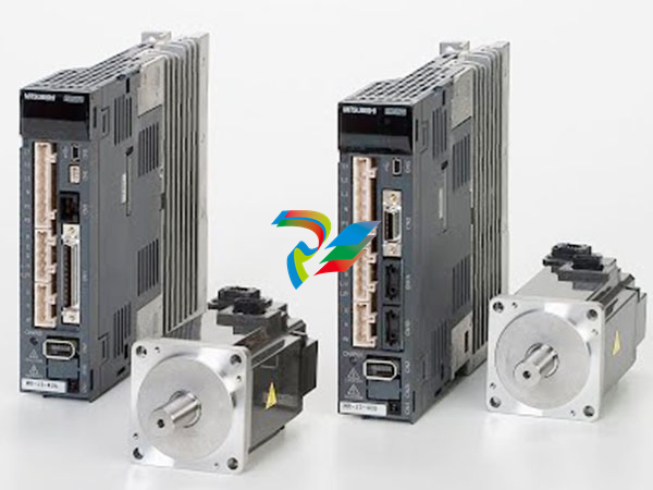
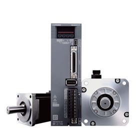
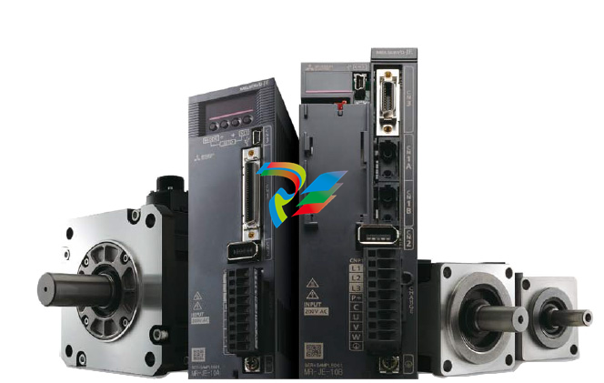
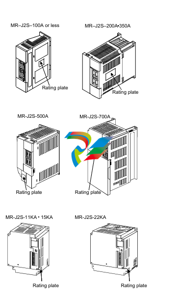 Mitsubishi MELSERVO-J2-Super series general-purpose AC servo
 -
 Mitsubishi MELSERVO-J3 servo system
 -
 Mitsubishi MELSERVO-JE servo system
 -
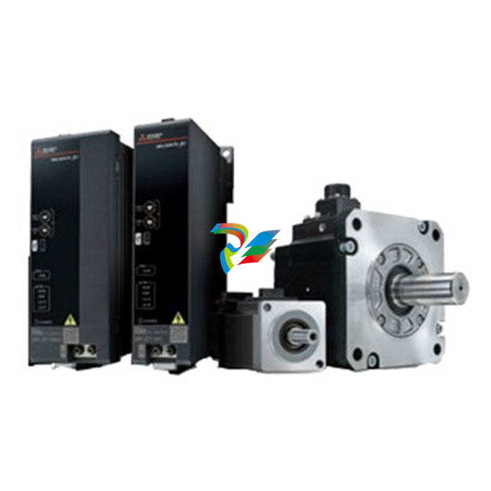
 Mitsubishi MELSERVO-J4 AC servo
 -
 Mitsubishi MELSERVO-JET servo system
 -
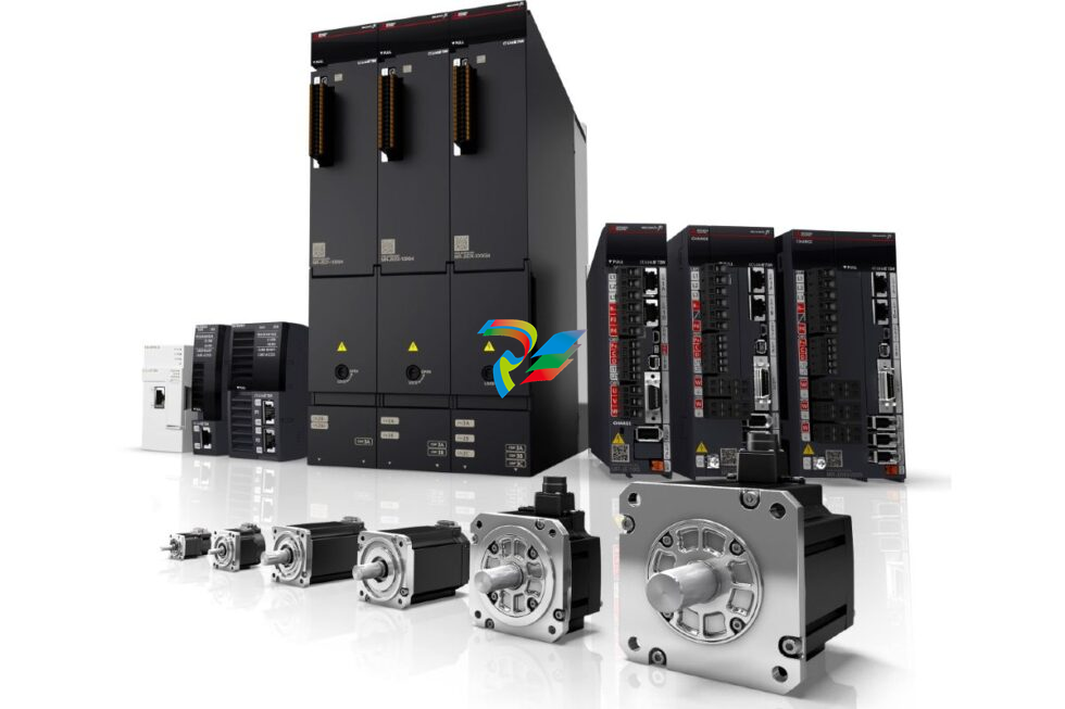 Mitsubishi MELSERVO-J5 AC servo
 -
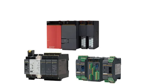
 Mitsubishi Melsec-related network products
 -
 Mitsubishi MELSEC-QS/WS series
 -
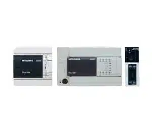 Mitsubishi MELSEC-F series
 -
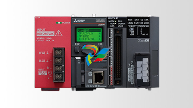 Mitsubishi MELSEC-L series
 -
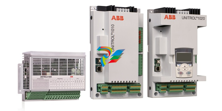
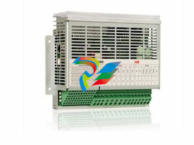 ABB UNITROL 1005 Automatic voltage regulator
 -
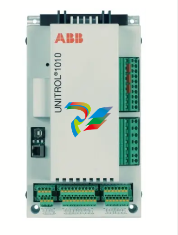 ABB UNITROL 1010 medium synchronous generators and industrial machines
 -
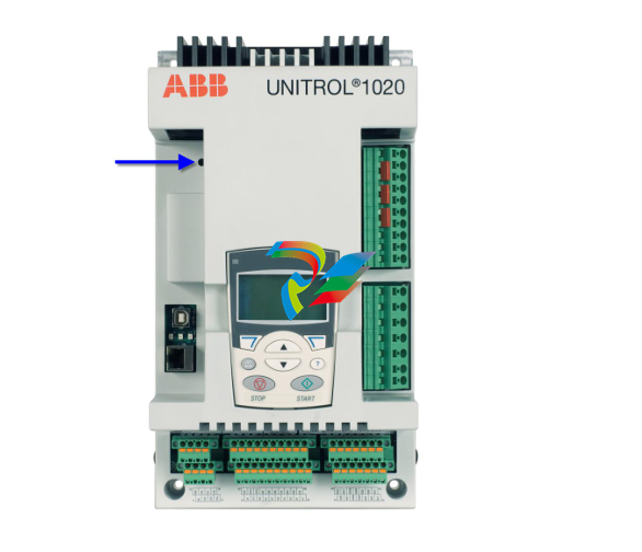 ABB UNITROL 1020 Synchronous voltage regulator
 -
 UNITROL 1000 Automatic voltage regulators (AVR)
 -
 Bently Nevada 3500/65 145988-02 temperature monitor
 -
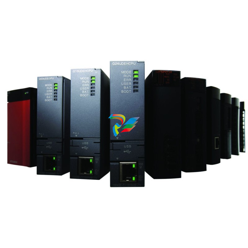 Mitsubishi MELSEC-Q series
 -
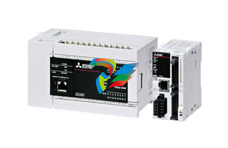 Mitsubishi MELSEC iQ-F series
 -
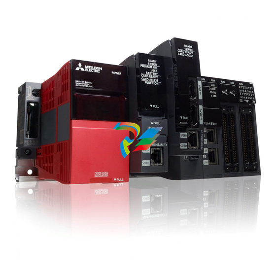 Mitsubishi MELSEC iQ-R series
 -
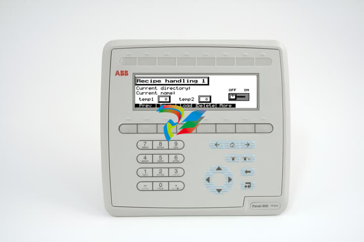 ABB IndustrialIT Panel 800 - PP820
 -
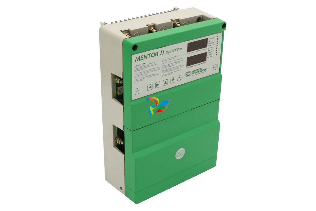 MENTOR II M25RGB14 Controller
 -
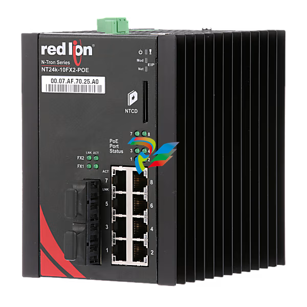 N-Tron® NT24K-10FX2-SC-POE Managed 10-Port Industrial Ethernet Switch
 -
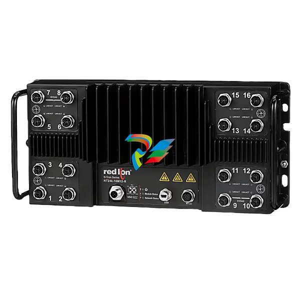 N-Tron® NT24K-16M12-POE-PT Managed 16-Port IP67 Gigabit Industrial Ethernet Switch
 -
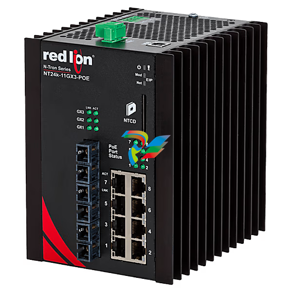 N-Tron® NT24K-11GX3-SC-POE Managed 11-Port Gigabit Industrial Ethernet Switch
 -
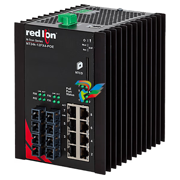 N-Tron® NT24K-12FX4-ST-POE Managed 12-Port Gigabit Industrial Ethernet Switch
 -
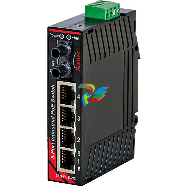
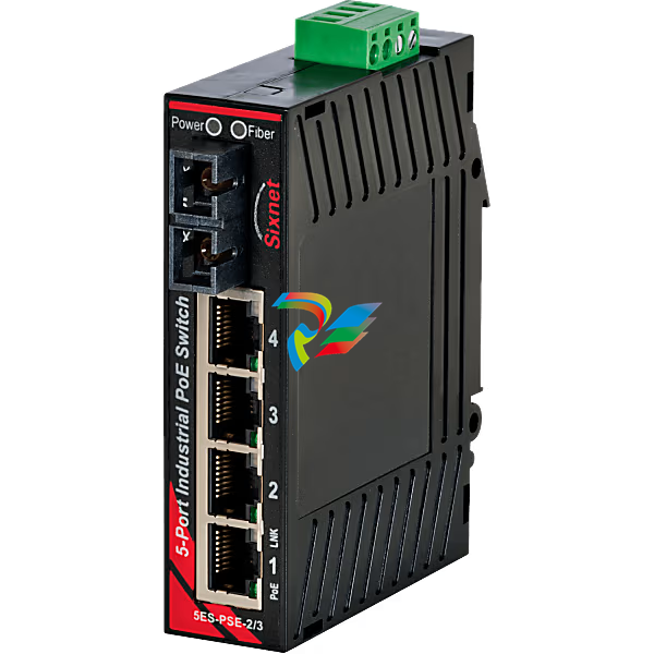
 Sixnet® EB-5ES-PSE-2SC Unmanaged 5-port PoE Industrial Switch
 -
 NT24k® 10FX2-POE Managed PoE+ Gigabit Ethernet Switch
 -
N-Tron® NT24K-16M12-POE-R-PT Managed 16-Port IP67 Gigabit Industrial Ethernet Switch
-
 N-Tron® NT24K-8TX-POE-PT Managed 8-Port Gigabit Industrial Ethernet Switch
 -
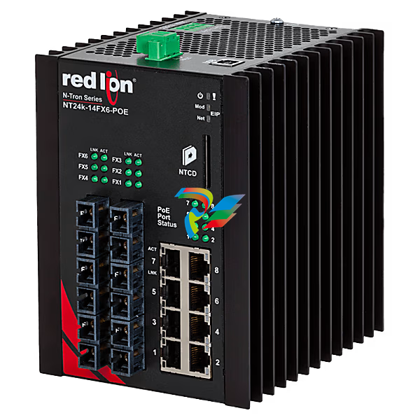 N-Tron® NT24K-14FX6-ST-POE Managed 14-Port Gigabit Industrial Ethernet Switch
 -
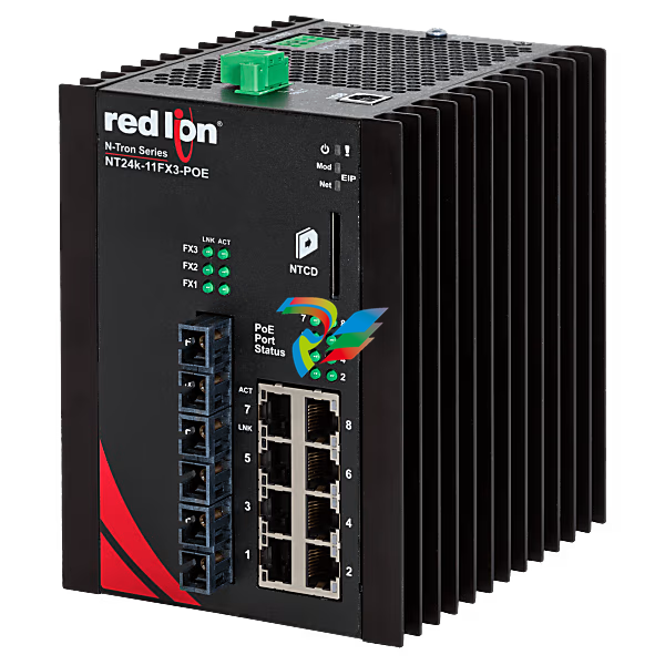 N-Tron® NT24K-11FX3-ST-POE Managed 11-Port Gigabit Industrial Ethernet Switch
 -
 N-Tron® 105FXE-ST-40-POE-MDR Unmanaged 5-port PoE Switch
 -
 Sixnet® EB-5ES Unmanaged 5-port PoE Industrial Switch, ST 60km
 -
 N-Tron® 100-POE4-MDR Industrial Midspan Injector, Metal DIN Rail
 -
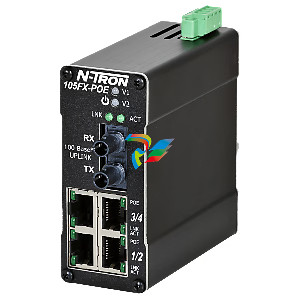
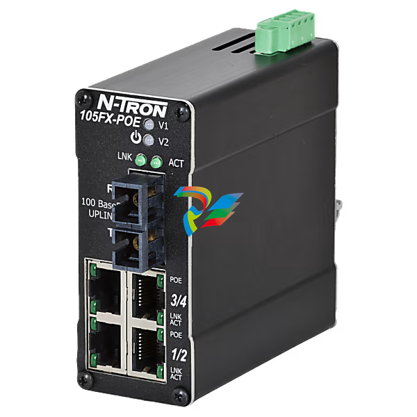
 N-Tron® 105FX-ST-POE Unmanaged 5-port PoE Switch
 -
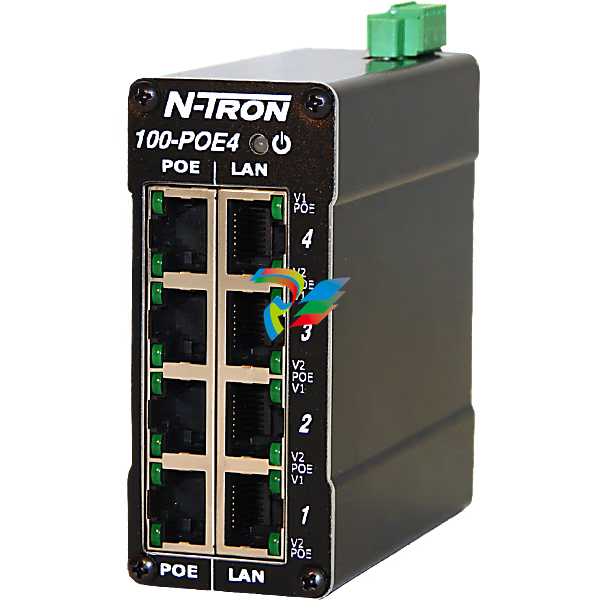
N-Tron® 100-POE4 Industrial Midspan Injector
-
N-Tron® NT24K-16M12-POE Managed 16-Port IP67 Gigabit Industrial Ethernet Switch
-
 N-Tron® 105FX-ST-POE-MDR Unmanaged 5-port PoE Switch
 -
 N-Tron® 105FXE-ST-15-POE Unmanaged 5-port PoE Switch
 -
Sixnet® EB-5ES-PSE-3ST Unmanaged 5-port PoE Industrial Switch
-
 N-Tron® 105FX-SC-POE Unmanaged 5-port PoE Switch
 -
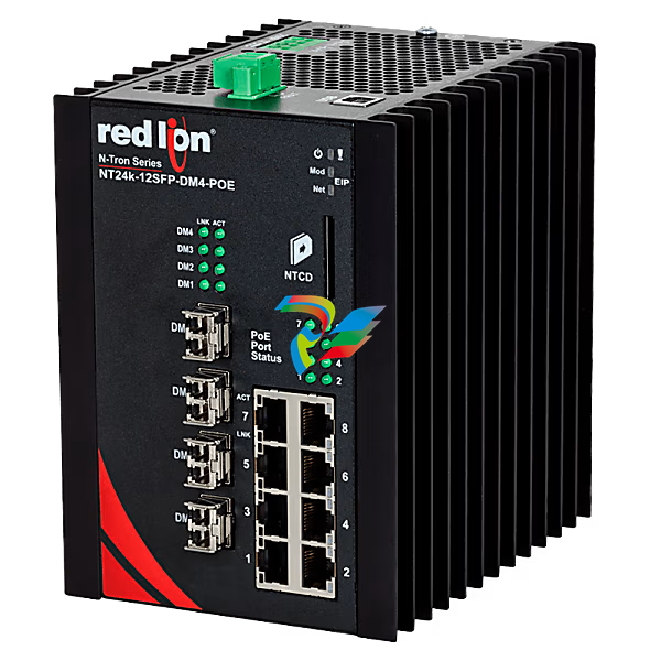 N-Tron® NT24K-12SFP-DM4-POE Managed 12-Port Gigabit Industrial Ethernet Switch
 -
N-Tron® NT24K-12FX4-SC-POE Managed 12-Port Gigabit Industrial Ethernet Switch
-
 N-Tron® 105FXE-ST-80-POE-MDR Unmanaged 5-port PoE Switch
 -
N-Tron® NT24K-14FX6-SC-POE Managed 14-Port Gigabit Industrial Ethernet Switch
-
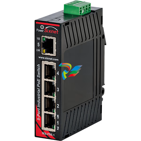
Sixnet® EB-5ES-PSE-1 Unmanaged 5-port PoE Industrial Switch
-
N-Tron® NT24K-16M12-POE-R Managed 16-Port IP67 Gigabit Industrial Ethernet Switch
-
N-Tron® NT24K-11FX3-SC-POE Managed 11-Port Gigabit Industrial Ethernet Switch
-
 N-Tron® 105FXE-SC-15-POE Unmanaged 5-port PoE Switch
 -
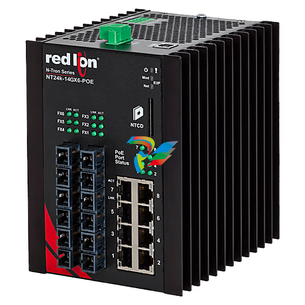 N-Tron® NT24K-14GX6-SC-POE Managed 14-Port Gigabit Industrial Ethernet Switch
 -
 N-Tron® 105FXE-SC-80-POE Unmanaged 5-port PoE Switch
 -
 N-Tron® 105FXE-SC-40-POE-MDR Unmanaged 5-port PoE Switch
 -
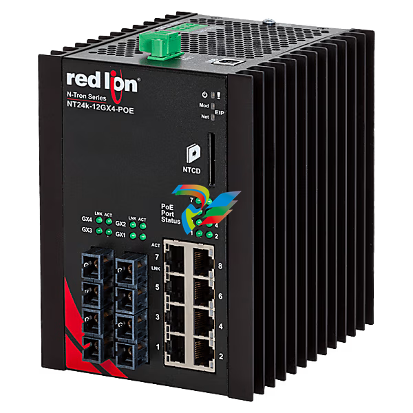 N-Tron® NT24K-12GX4-SC-POE Managed 12-Port Gigabit Industrial Ethernet Switch
 -
 Sixnet® EB-5ES Unmanaged 5-port PoE Industrial Switch, SC 20km
 -
 N-Tron® 105FXE-ST-15-POE-MDR Unmanaged 5-port PoE Switch
 -
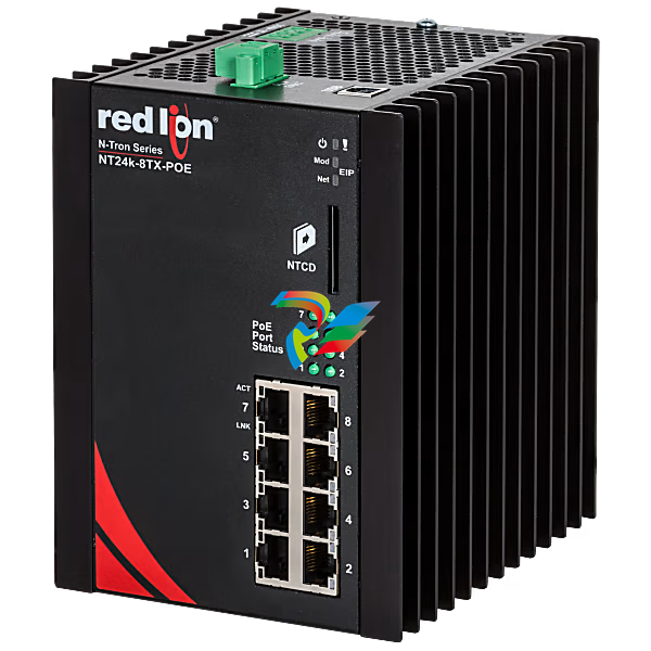 N-Tron® NT24K-8TX-POE Managed 8-Port Gigabit Industrial Ethernet Switch
 -
 N-Tron® 105FX-SC-POE-MDR Unmanaged 5-port PoE Switch
 -
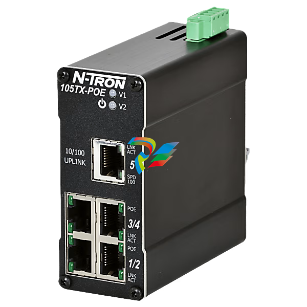
 N-Tron® 105TX-POE Unmanaged 5-port PoE Switch
 -
 Sixnet® EB-5ES Unmanaged 5-port PoE Industrial Switch, SC 60km
 -
 N-Tron® 105FXE-SC-15-POE-MDR Unmanaged 5-port PoE Switch
 -
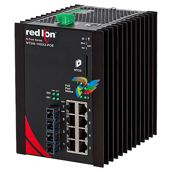 N-Tron® NT24K-10GX2-SC-POE Managed 10-Port Gigabit Industrial Ethernet Switch
 -
 N-Tron® 105TX-POE-MDR Unmanaged 5-port PoE Switch
 -
 N-Tron® 105FXE-ST-80-POE Unmanaged 5-port PoE Switch
 -
 N-Tron® 105FXE-SC-80-POE-MDR Unmanaged 5-port PoE Switch
 -
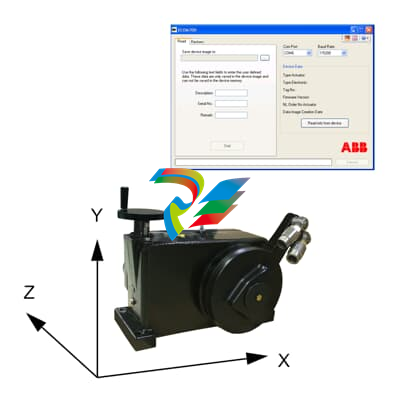 ABB Electrical actuators accessories ECOM700
 -
 Electronic unit EBS862 ABB
 -
ABB Electronic unit EBS852
-
 Electronic unit EAS822 ABB
 -
 Electronics EBN861 ABB
 -
 ABB Electronic unit EBN853
 -
 Electronic unit EAN823 ABB
 -
 Electrical linear actuator RSD100 (Contrac)
 -
 Electrical linear actuator RSD50 (Contrac)
 -
 ABB Electrical linear actuator RSD20 (Contrac)
 -
Electrical linear actuator RSD10 (Contrac)
-
 Linear actuator LME620-AI/-AN (Contrac)
 -
 abb Electrical rotary actuator RHD16000 (Contrac)
 -
ABB Electrical rotary actuator RHD8000 (Contrac)
-
 Electrical rotary actuator RHD4000 (Contrac)
 -
Electrical rotary actuator RHD1250 / RHD2500 (Contrac)
-
 Electrical rotary actuator RHD500 / RHD800 (Contrac)
 -
 Electrical rotary actuator RHD250 (Contrac)
 -
Rotary actuator PME120-AI/-AN (Contrac)
-
 I/P converters TEIP11 / TEIP11-PS
 -
 Digital positioner TZIDC-220 ABB
 -
 Digital positioner TZIDC-210 ABB
 -
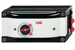 ABB Digital positioner TZIDC-200
 -
 Digital positioner TZIDC-120 ABB
 -
 Digital positioner TZIDC-110 ABB
 -
Digital positioner TZIDC ABB
-
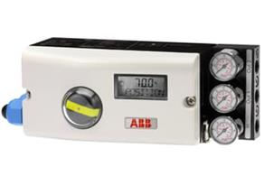
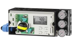
 Digital positioner PositionMaster EDP300 ABB
 -
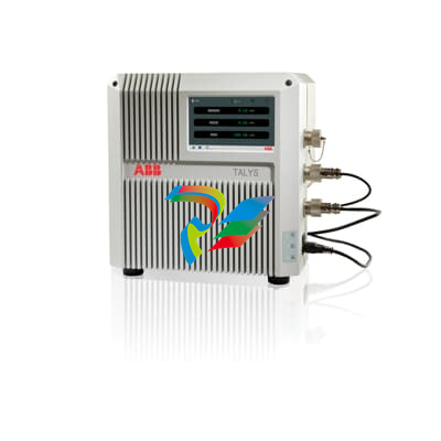
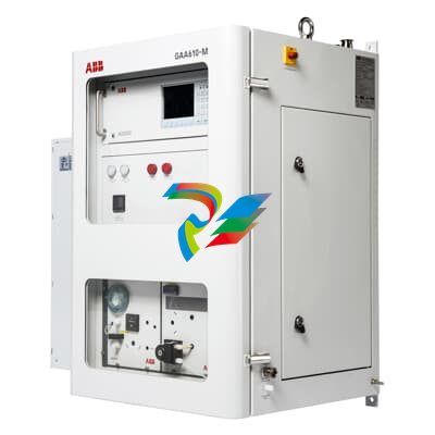
 TALYS ADP300 series Dual channel wet process analyzer
 -
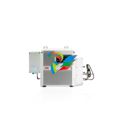 FT-NIR analyzer TALYS ASP400 series ABB
 -
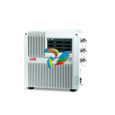
 Wet bath monitoring analyzer TALYS ASP300 series
 -
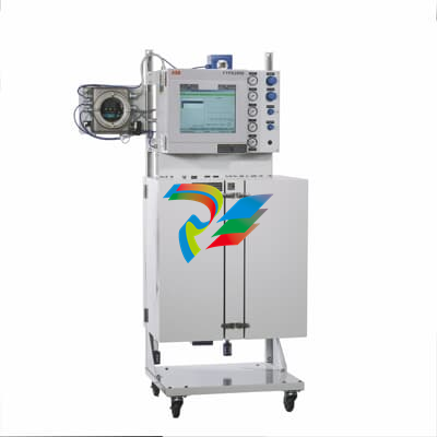 ABB FTPA2000-HP460 FT-NIR process analyzer
 -
 FT-NIR process analyzer for hydrocarbon FTPA2000-HP360
 -
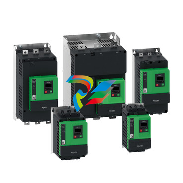 Altivar Soft Starter ATS430
 -
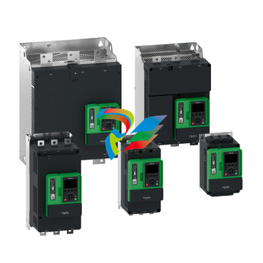 Altivar Soft Starter ATS490
 -
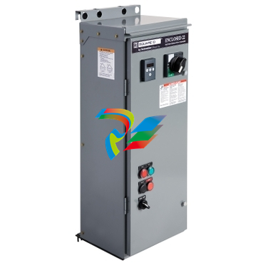
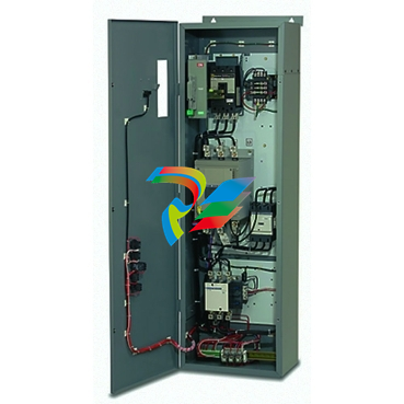 Soft Start - ATS48 Enclosed From 3HP to 600HP-
 -
 Soft Start - ATS22 Enclosed From 3HP to 500HP
 -
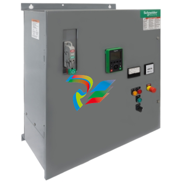 Altivar ATS480 Enclosed Soft Starter System
 -
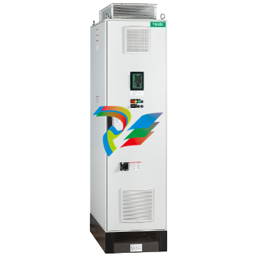 Altivar Process 680 AFE Low Harmonic Drive
 -
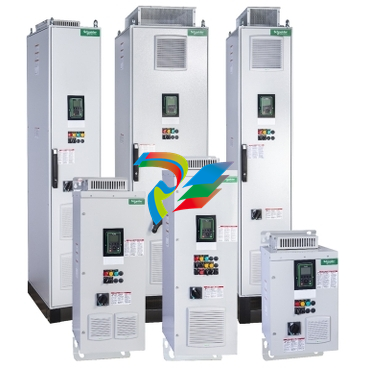 Altivar Process 660 Drive System
 -
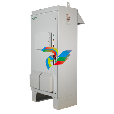 Altivar Outdoor Drive Utilizing the ATV 630/930 Process Drives
 -
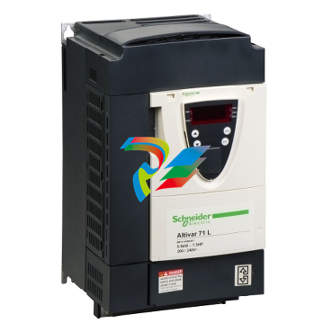 Altivar 71 Variable Frequency Drives VFD
 -
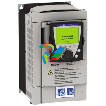 Altivar 61 Variable Frequency Drives VFD
 -
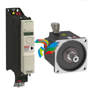 Altivar 32 Variable Frequency Drive VFD
 -
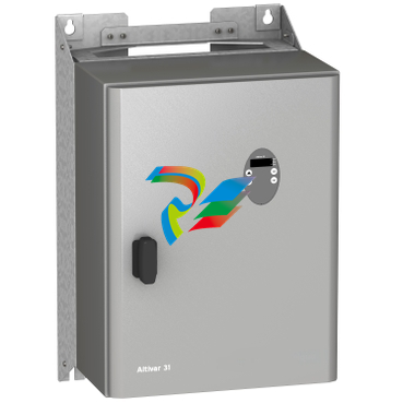 Altivar 31C Variable Frequency Drive VFD
 -
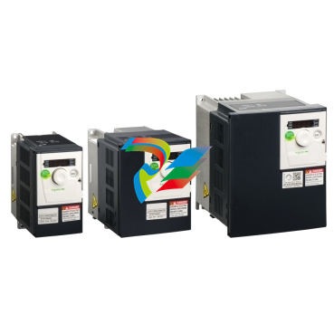 Altivar 312 Variable Frequency Drives VFD
 -
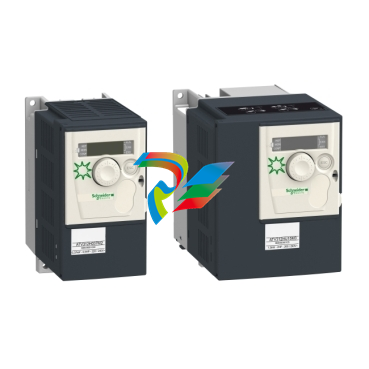 Altivar 312 Solar Variable speed drives for pumps with photovoltaic arrays
 -
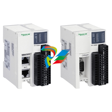 Modicon OTB IP20 optimum modular I/O system
 -
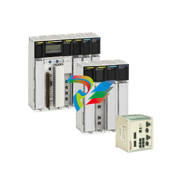 Schneider Modicon Quantum PAC
 -
 Schneider Modicon ABE9
 -
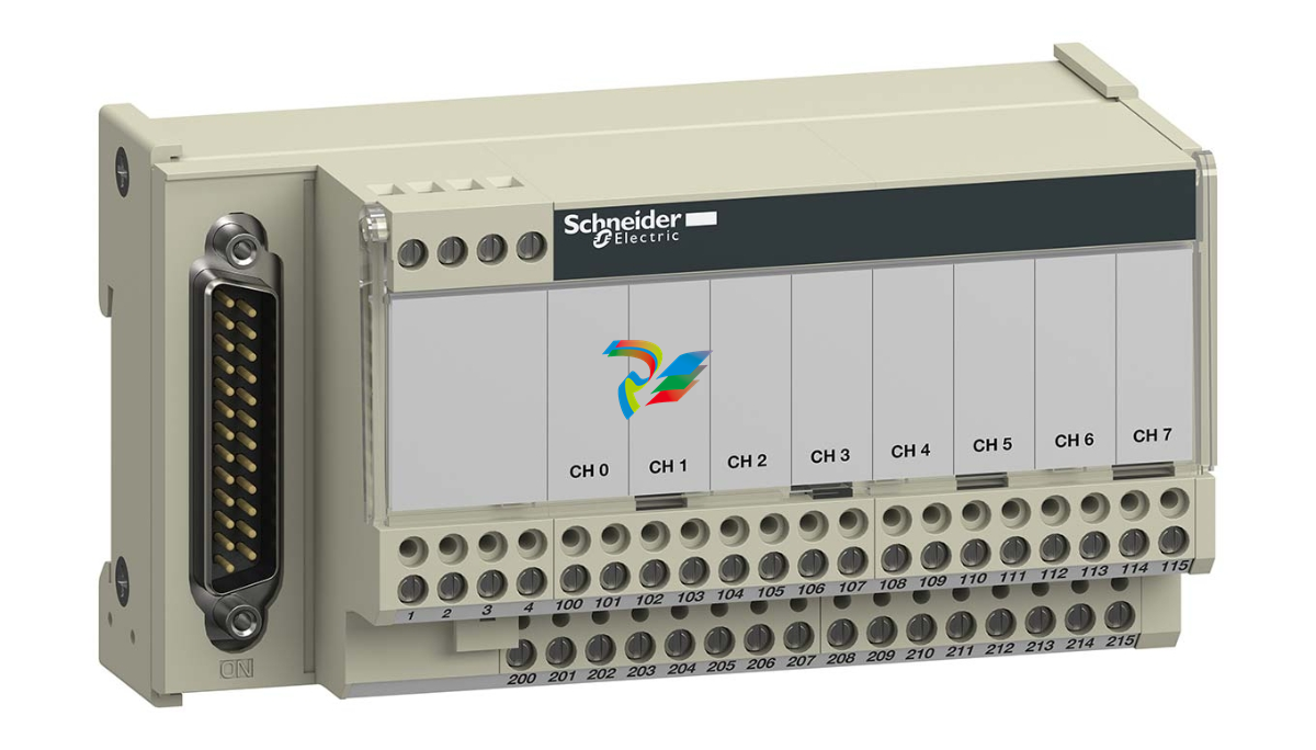 Schneider Advantys Telefast ABE 7
 -
 Modicon TM7 Remote I/O for Harsh Environments
 -
 Modicon Momentum
 -
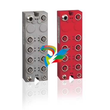
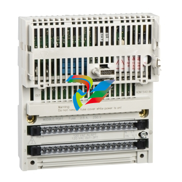
 Modicon STB IP20 modular distributed I/O
 -
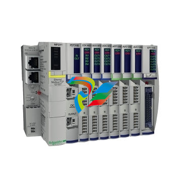
 Modicon TM5 IP20 Modular I/O System
 -
 Modicon Edge I/O NTS
 -
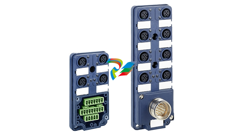
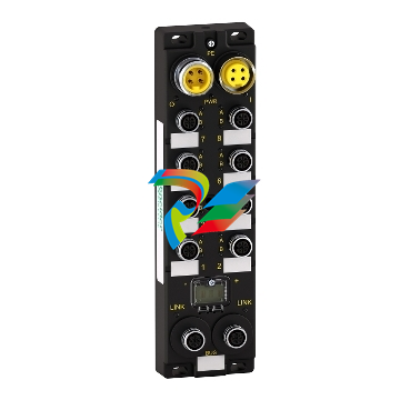 Modicon ETB IP 67 modular distributed I/O for Ethernet
 -
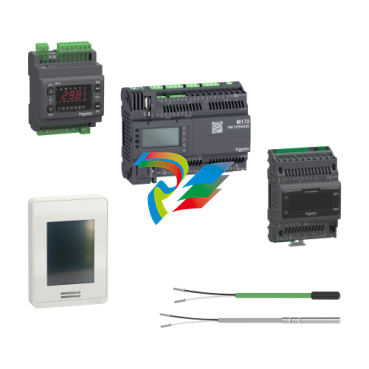 Modicon M171/M172 Logic Controller
 -
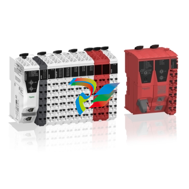
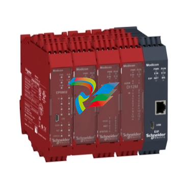 Modicon MCM Safety controllers
 -
 EcoStruxure™ OPC UA Server Expert
 -
 Modicon MC80 Compact Process Automation Controller
 -
Modicon M340 PAC
-
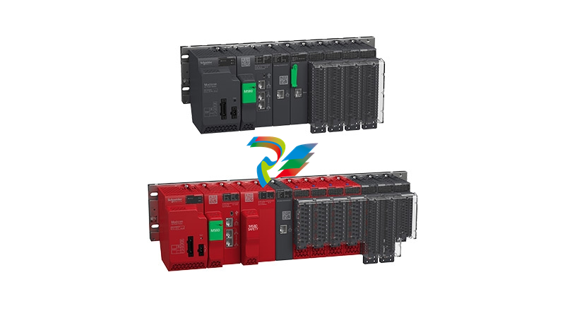 Modicon M580 PAC Controller
 -
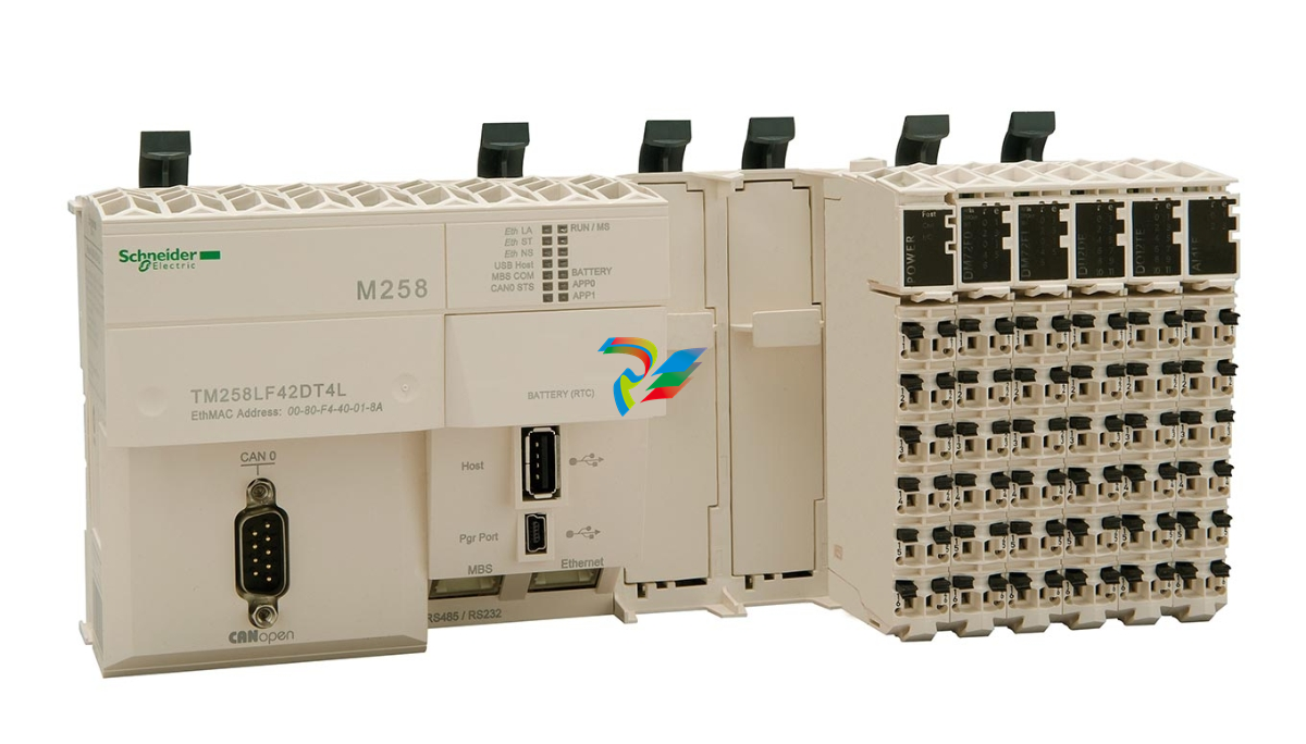 Modicon M258 Compact PLC for Machine Automation
 -
 Schneider Logic/Motion controller Modicon M262
 -
 Modicon M251 Micro PLC with Dual Channel Comm Schneider

