
ABB Advant Controller 31
Kommunikationsmodul 07 KP 90 R303 Kommunikation über RCOM-Protokoll
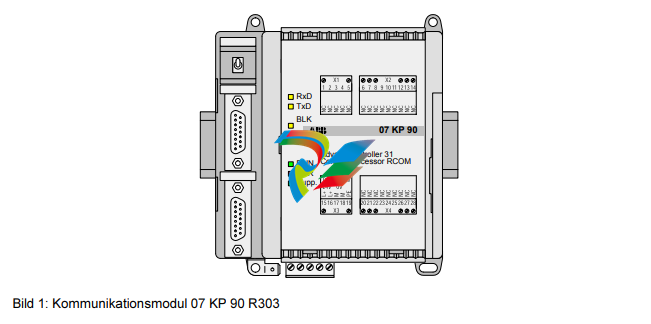
1.1 Kurzbeschreibung
Das Kommmunikationsmodul RCOM 07 KP 90 R303 kann
als Erweiterungsgerät an Grundgeräte wie 07 KR 91 R353
07 KT 92, 07 KT 93, 07 KT 94 des dezentralen Automatis
ierungssystems Advant Controller 31 angeschlossen werden.
Das Kommunikationsmodul 07 KP 90 R303 ermöglicht eine
Kommunikation über das RCOM-Protokoll. Über dieses Proto
koll kann ein Datenaustausch · zwischen ABB Master Piece
200 Leitsystemen, ABB Procontic T200 Systemen und Advant
Controller 31 Systemen, oder · zwischen Advant Controller 31
Systemen untereinander stattfinden.
Von Vorteil ist, daß sich mit RCOM (Remote COMmunication) gro
ße Entfernungen überbrücken lassen. Die Kommunikation kann
über verschiedene Übertragungsmedien erfolgen, wie z. B.: · ge
mietete oder private Standleitungen, · vorhandene Kabelwege,
· Telefonleitungen (Wählverbindungen). Die Anpassung an den
gewünschten Übertragungsweg kann durch die Auswahl unters
chiedlicher Modems erreicht werden (z. B. Tonfrequenz- oder St
romschleifenModems, Telefon-Modems, Multidrop-Modems). Ein
RCOM-Netzwerk besteht immer aus einem Master und einem od
er mehreren Slaves, wobei es folgende Möglichkeiten für die Da
tenübertragung gibt: · Master sendet Daten an einen Slave · M
aster liest Daten von einem Slave · Event-gesteuerte (ereignisg
esteuerte) Übertragung: Ein Slave kann Prozeßereignisse mit ei
ner Zeitkennung speichern und auf Anforderung zum Master übertragen (Event Polling)
1.2 Merkmale
Das Kommunikationsmodul RCOM 07 KP 90 R303 ist
als RCOM-Master oder -Slave projektierbar. · Es sind
bis zu 254 RCOM-Slaves in einem Netzwerk (max. 8
Slaves bei Einsatz mit Master Piece 200, max. 30 Sla
ves bei Wählbetrieb) möglich.
· Das RCOM-Protokoll ist kompatibel zu MP200/1 mit
DSCA 180A. Alle RCOM-Dienste sind verfügbar (Kaltst
art, Warmstart, Normalisierung, Uhr-Synchronisation,
Daten schreiben, Daten lesen, Event Polling). · Die R
COM-Schnittstelle zum Anschluß des Modems entspri
cht EIA RS-232. Zusätzlich ist ein Betrieb nach EIA R
S-485 möglich. · Eine zusätzliche Bediener-Schnittste
lle (CONSOLE) nach EIA RS-232 als Inbetriebnahme-
Hilfsmittel (Anzeige des Kommunikationsablaufs, Pro
jektierung von Telefonnummern etc.) ist vorhanden.
· Software-Uhr, Uhrzeit kann im SPS-Programm verw
endet werden. · Unterschiede zwischen RCOM und R
COM+ siehe Software-Ordner 907 KP 90 R202, Griff
3, Kapitel 2.6. Alle anderen Eigenschaften von RCOM
, die nicht im Kapitel Unterschiede genannt sind, gelt
en entsprechend auch für RCOM+. · Das Verknüpfun
gselement RCOM+ kann mit dem Kommunikationsm
odul 07 KP 90 ab Index b eingesetzt werde
1.3 Projektierung mit dem Software-Paket 907 KP 90 R202
Die Projektierung des Kommunikationsablaufs erfolgt mit
Verknüpfungselementen, die im Dokumentations- und So
ftware-Paket 907 KP 90 R202 enthalten sind (vgl. Bestelld
aten). Dieses Paket enthält auch das Handbuch für das Ko
mmunikationsmodul RCOM 07 KP 90 R303 sowie Beispiele
zur Projektierung.
1.4 Aufbau der Frontseite
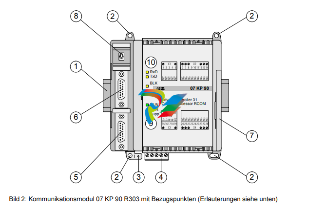
1 Befestigung des Gerätes auf Hutprofilschiene
2 Befestigung des Gerätes durch Anschrauben
3 Erdungsanschluß 6,3 mm Faston
4 Versorgungsspannung 24 V DC
5 Serielle Schnittstelle CONSOLE
6 Serielle Schnittstelle RCOM
7 Vernetzungsschnittstelle zur Advant Controller 31 Zentraleinheit
8 Schalter
9 LED-Anzeigen siehe unten
10 LED-Anzeigen siehe unten
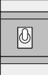
Der Schalter ist ohne Funktion.
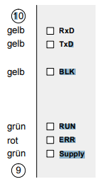
07 KP 90 empfängt ein RCOMTelegramm
07 KP 90 sendet Daten über die Rcom-Schnittstelle
Übertragung von Nutzdaten durch
Kommunikationsfehler blockiert
07 KP 90 R303 ist bereit für RCOM-Kommunikation (läuft
RCOM-Kommunikationsfehler
Versorgungsspannung vorhanden
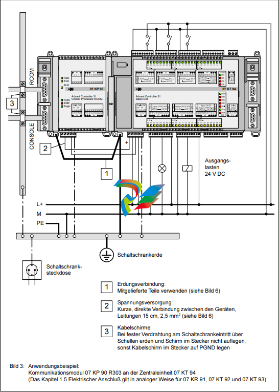
1.5 Technische Daten Allgemein gelten als technische Daten die Angaben in Kapitel
1 Systemdaten und Systemaufbau, Griff 2 der Systembeschreibung Advant Controller 31. Ergänzende und davon abweichende Daten werden im folgenden aufgeführt.
1.6.1 Übersichtsdaten
1.6.1 Übersichtsdaten Anzahl der seriellen Schnittstellen 4 Anzahl der parallelen Schnittstellen 1 Vernetzungsschnittstelle zum Anschluß an die Advant Controller 31 Zentraleinheit
Eingebauter Applikations-Software-Speicher Flash-EPROM 128 kByte Diagnose
4 projektierbare LEDs: LED1...4 (Steuerung vom Applikations-Programm aus)
Betriebs- und Fehleranzeigen 3 LEDs: RUN, ERR, Supply Leiterquerschnitt für
die abziehbaren max. 2,5 mm2 Anschlußklemmen
1.6.2 Geräteversorgung 07 MK 92 R1161
Versorgungsnennspannung 24 V DC Leistungsaufnahme
typ. 2,5 W max. Stromaufnahme bei Nennspannung 210
mA bei Versorgungsspannung 30 V 170 mA Verpolschutz
ja (nur, wenn an COM5/COM6 Geräte mit potentialfreien
Schnittstellen angeschlossen werden.)
1.6.3 Anschluß serielle Schnittstellen COM3, COM4
Schnittstellennorm EIA RS-232 oder EIA RS-422
oder EIA RS-485Programmierung mit
907 MK 92 über IBM-PC (oder kompatibel)
Mensch-Maschine-Kommunikation ja, z. B.
über BedienstationPotentialtrennung ja,
Schnittstellen gegeneinander und gegenüber dem
-
 AEROTECH SM Series High-Performance Stepper Motors
 -
 AEROTECH BLMSC Series Linear Motors
 -
 AEROTECH Custom Linear Motors
 -
 AEROTECH BMS Series Brushless, Slotless Rotary Motors
 -
 AEROTECH BM Series Brushless Rotary Motors
 -
 AEROTECH BLMX Series Linear Motors
 -
 AEROTECH BLMH Series Linear Motors
 -
 AEROTECH BLM Series Linear Motors
 -
 AEROTECH BLMC Series Linear Motors
 -
 AEROTECH BLMUC-143 Linear motor forcer with thermistor
 -
AEROTECH BLMUC-111 Linear motor forcer with thermistor
-
AEROTECH BLMUC-95 Linear motor forcer with thermistor
-
AEROTECH BLMUC-79 Linear motor forcer with thermistor
-
AEROTECH BLMUC Series Linear Motors
-
 AEROTECH Automation1 FLEX Distributed Amplifier Multi-Axis Servo Control System
 -
 AEROTECH Automation1 HXA4 6-Axis Hexapod Servo Drive
 -
 AEROTECH Automation1 iHXA4 6-Axis Hexapod Servo Drive with Motion Controller
 -
 AEROTECH Modular System Control Console
 -
 AEROTECH TV Series Transformers
 -
 AEROTECH TM Series Transformers
 -
 AEROTECH UFM Noise Filter Module
 -
 AEROTECH MFM Motor Filter Module
 -
 AEROTECH MPG Handwheel Pendant
 -
 AEROTECH Automation1 Multi-Axis Joystick
 -
 AEROTECH ETM Enhanced Throughput Module
 -
 AEROTECH Automation1 XL4s High-Speed, Single-Phase Linear Servo Drive
 -
 AEROTECH Automation1 XL2e Enhanced, Compact Linear Servo Drive
 -
 Automation1 iXL2e Enhanced, Compact Linear Servo Drive with Motion Controller
 -
 AEROTECH Automation1 XL5e Enhanced, Linear Servo Drive
 -
 AEROTECH Automation1 iXL5e Enhanced Linear Servo Drive with Motion Controller
 -
 AEROTECH Automation1 GI4 Laser Scan Head Controller
 -
 AEROTECH Automation1 SI4 Stepper Interface
 -
AEROTECH Automation1 XI4 Servo Interface
-
 AEROTECH AEROTECH Automation1 iXI4 Servo Interface with Motion Controller
 -
 AEROTECH Automation1 XC6e Enhanced, High-Power PWM Servo Drive
 -
 AEROTECH Automation1 iXC6e Enhanced, High-Power PWM Servo Drive with Motion Controller
 -
 AEROTECH Automation1 XC2 Compact PWM Servo Drive
 -
 AEROTECH Automation1 XC4 PWM Servo Drive
 -
 AEROTECH Automation1 GL4 Galvo Laser Scan Head Linear Drive
 -
 AEROTECH Automation1 XC2e Enhanced, Compact Servo Drive with PWM+
 -
 AEROTECH Automation1 XC4e Enhanced, PWM Servo Drive
 -
 AEROTECH Automation1 XR3 Multi-Axis Servo Drive Rack
 -
 AEROTECH Automation1 iXR3 Multi-Axis Servo Drive Rack with Motion Controller
 -
 AEROTECH Automation1 iXC2 Compact PWM Servo Drive with Motion Controller
 -
 AEROTECH Automation1 iXC2e Enhanced, Compact PWM+ Servo Drive with Motion Controller
 -
 AEROTECH Automation1 iXC4 PWM Servo Drive with Motion Controller
 -
 AEROTECH Automation1 iXC4e Enhanced, PWM Servo Drive with Motion Controller
 -
 AEROTECH Automation1 iPC Industrial PC with Motion Controller
 -
 AEROTECH EPICS & TANGO Drivers for Distributed Control Systems
 -
 AEROTECH .NET, C, Python & LabVIEW APIs Custom Application Develotpmen
 -
 AEROTECH Automation1 Industrial Ethernet Support
 -
 AEROTECH Automation1 iSMC Intelligent, Software-Based Motion Controller
 -
 AEROTECH Automation1 iXA4 1- 2- or 4-Axis PWM Servo Drive with Motion Controller
 -
 AEROTECH Automation1 XA4 1- 2- or 4-Axis PWM Servo Drive
 -
 CTI 2500-ADP2-DISC Discrete Wiring Adapter for Series 500
 -
 CTI 2500-ADP1 Analog Wiring Adapter for Series 500
 -
 CTI 2500C-RADP-RS485 Remote Base Controller Adapter for Series 500
 -
 CTI 2500C-RADP-RBC Profibus RBC Adapter for Series 500
 -
 CTI 2500C-PADP-120V 120VAC 50W Power Supply for Series 500
 -
 CTI 2500-RADP RBC Adapter for Series 500
 -
 CTI 2500-R4500 520/530/DBC Adapter for Series 500 - MATURE
 -
 CTI 2500-PADP Power Supply Adapter for Series 500
 -
 CTI 2500-IADP I/O Adapter for Series 500
 -
 CTI 2500-VP15A-N4-W7 15" Flat-Panel PC with Windows® 7 Embedded
 -
 CTI 2500S-27-1750 Slice I/O, Ethernet, RS232/485. 900MHz, 2DIO / 4UAI / 2AI
 -
 CTI 2500S-26-1750 Slice I/O, Ethernet, RS232/485. 900MHz, 8DIO / 2UAI
 -
 CTI 2500S-23-1750 Slice I/O, Ethernet, RS232/485. 900MHz, 4DI / 4DO / 2UAI / 2AO
 -
 CTI 2500S-27-1550 Slice I/O, RS232/485. 2DIO / 4UAI / 2AI
 -
 CTI 2500S-26-1550 Slice I/O, RS232/485. 8DIO / 2UAI
 -
 CTI 2500S-23-1550 Slice I/O, RS232/485. 4DI / 4DO / 2UAI / 2AO
 -
 CTI 2500S-27-1050 Slice I/O, Ethernet, 2DIO / 4UAI / 2AI
 -
 CTI 2500S-26-1050 Slice I/O, Ethernet, 8DIO / 2UAI
 -
 CTI 2500S-23-1050 Slice I/O, Ethernet, 4DI / 4DO / 2UAI / 2AO
 -
 CTI 2500C-32F-CJC 32-Pin Field Wiring Connector with Cold Junction Compensation
 -
 CTI 2500C-32F 32-Pin Field Wiring Connector
 -
 CTI 2500C-8-TC Eight Thermocouple Inputs
 -
 CTI 2500C-8-RTD Eight RTD Inputs
 -
 CTI 2500C-8-RL-FC 8 Form-C Relay Outputs
 -
 CTI 2500C-8-IDO-24V 8 Isolated 24VDC Outputs
 -
 CTI 2500C-8-IDO-120V 8 Isolated 120VAC Outputs
 -
 CTI 2500C-16-DO-24V Sixteen 24VDC Digital Outputs
 -
 CTI 2500C-16-DO-120V Sixteen 120VAC Digital Outputs
 -
.png) CTI 500C-16-IDI-24V Sixteen Isolated 24V AC/DC Digital Inputs
CTI 500C-16-IDI-24V Sixteen Isolated 24V AC/DC Digital Inputs -
 CTI 2500C-16-IDI-120V Sixteen Isolated 120V AC/DC Digital Inputs
 -
 CTI 2500C-16-DIDO-SIM Sixteen Digital Input and Output SImulator
 -
 CTI 2500C-16-DI-24V Sixteen 24V AC/DC Digital Inputs
 -
 CTI 2500C-16-DI-120V Sixteen 120V AC/DC Digital Inputs
 -
 CTI 2500C-RBC-RS485 RS485 Remote Base Controller
 -
 CTI 2500C-RBC-PRF Profibus Remote Base Controller
 -
 CTI 2500C-PS-24V-35 35-Watt DC Power Supply
 -
 CTI 2500C-PS-120V-35 35-Watt AC Power Supply
 -
 CTI 2500C-R8 Eight-Slot Base
 -
 CTI 2500C-R4 Four-Slot Base
 -
 CTI 2500C-R16 Sixteen-Slot Base
 -
 CTI 2500C-2572-B Fast Ethernet TCP/IP Adapter
 -
 CTI 2500C-J750 Compact Janus PAC with 3MB Project Memory
 -
 CTI 2500C-C300 CPU with 512K User Memory
 -
 CTI 2500C-C200 CPU with 256K User Memory
 -
 CTI 2500C-C100 CPU with 128K User Memory
 -
 CTI 2500C-8-AO 8 Analog Outputs
 -
 CTI 2500C-8-AI 8 Analog Inputs
 -
 CTI 2559-FCAL Precision Calibration Connector
 -
 CTI 2559-FPC 40-Position Screw-Terminal Connector
 -
 CTI 2500-RFC PLC to RF Modem Cable
 -
 CTI 2500-40F 40-Position Standard Screw-Terminal Connector
 -
 CTI 2505 Vibration Sensor Interface Module
 -
 CTI 2554-A 4-Channel Isolated High Speed Counter Module
 -
 CTI 2553-A 2-Channel Mag Meter Input Module
 -
 CTI 2502 2-Channel High Speed Counter Input Module
 -
 CTI 2559-TC 8-Channel Thermocouple Input Module
 -
 CTI 2556-A 16-Channel Isolated Thermocouple Input Module
 -
 CTI 2556 16-Channel Isolated Thermocouple Input Module
 -
 CTI 2551-A 8-Channel Isolated Thermocouple Input Module
 -
 CTI 2559-RTD 8-Channel RTD Input Module
 -
 CTI 2557-A 16-Channel RTD Input Module
 -
 CTI 2557 16-Channel RTD Input Module
 -
 CTI 2552-A 8-Channel Isolated RTD Input Module
 -
 CTI 2534 8-Point Form-C Relay Output Module
 -
 CTI 2532 16-Point Form-A Relay Output Module
 -
 CTI 2531 32-Point Form-A Relay Output Module
 -
 CTI 2530 8-Point Form-C Relay Output Module
 -
 CTI 2562 8-Channel Analog Output Module
 -
 CTI 2560-A 8-Channel Isolated Analog Output Module
 -
 CTI 2501 8in/4out Analog Module
 -
 CTI 2558 8-Channel Analog Input Module
 -
 CTI 2555-A 16-Channel Analog Input Module
 -
 CTI 2550-A 8-Channel Isolated Analog Input Module
 -
 CTI 2599 8/16/32-Point AC Output Module


