TYCOPSU830 POWER SUPPLY AND BATTERY CHARGER
PRODUCT APPLICATION AND DESIGN INFORMATION

INTRODUCTION
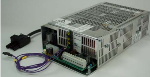
The PSU830 power supply is intended for use in MX/ZX/
ZXF/T2000/MX2 fire panels. It is a functional replacement for the PSB800, PSM800, PSB820 and PSB821.
The PSU830 provides the following features:
Power factor correction (PFC) to minimise loading
effects on the AC supply and allows operation from 120
- 240V ac.
Temperature compensated, battery charger for sealed
lead acid batteries:
Battery disconnection (load shed) when operating from
battery supply to provide deep discharge protection to
battery set
Fault monitoring includes:-
– battery disconnected, battery wiring short, battery
high resistance, battery voltage low, battery reverse,
temperature compensation fault, ac supply low,
internal charger fault
Common fault output - volt free relay contacts
Diagnostic LEDs for
– AC ok
– Battery fault
– Charger fault
– Ground (earth) fault
Two 27VDC fused field supply outputs with short circuit
protection, one output may be reset (turned off) under
command from fire panel
40VDC 2.2.A output for supplying up to 4 fully loaded
MX Digital loops, typically a single PSU830 may
replace two PSB800 40V 1.2A supplies
5VDC output for use within fire panel/repeater
Selectable Ground (earth) fault monitoring
Battery charging function of two PSU830 may be connected in parallel
TECHNICAL SPECIFICATION
The PSU830 complies with the requirements of:
EN 54-4/1997:A2-2006 Fire Detection and fire alarm
systems; part 4, Power supply equipment
SYSTEM COMPATIBILITY:
Use only with MX/MX2/ZX/ ZXF/T2000 Fire Alarm
Controllers
ENVIRONMENT
Indoor Application only, Land and Marine
Operating Temperature: -10o
to +55oC
Storage Temperature: -20o to +70oC
Operating Humidity: Up to 95% non-condensing
NOTICE
Sealed lead acid batteries cannot be reliably
charged when ambient air temperature
around them (the battery ambient) exceeds
50° C.
DIMENSIONS (HWD):
62 x 132 x 242mm
EMC
The PSU830 complies with the following:
Product family standard EN50130-4 in respect of Conducted Disturbances, Radiated Immunity, Electrostatic
Discharge, Fast Transients and Slow High Energy
EN 61000-6-3 for Emissions
ELECTRICAL CHARACTERISTICS
Input Voltage: 120-240Vac 50/60Hz (autoranging)
Input Current Rated Load: 0.8-2.2ARMS
Rated input power: 200W maximum
Outputs
– Non-reset:
27V dc @ 2A
5V dc @ 2.2A Rated, 3.0A max
40V dc @ 2.2 Rated, 2.3A max
– Reset: 27V dc @ 2A
+27V: 21-28.8Vdc (typically 27.3V with battery fully
charged)
+40V: 39.5-40.3Vdc
+5V: 4.8-5.25Vdc
Rated Output
Rated output of 5A to supply the panel, fire system
loads and charge 24V battery. De-rate to 4.5A when
used at 120VAC and ambient above 40ºC, e.g. some
T2000 Marine applications.
Maximum Alarm current 5A for 30 minutes
Maximum continuous load current (excluding charging) 2.5A
Rated output power: 136W
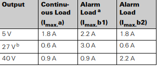
The PSU830 cannot support all outputs fully loaded, the
following output load combinations are possible in MX
panel application:
BATTERY CHARGER
A PSU830 may be used to charge 17Ah or 38Ah battery
sets. To meet the requirements of charge to 80% rated
capacity within 24 hours with a 38Ah battery set it is recommended that 2A or greater be allocated for battery
charging. Points to note:
Trickle charge determined by battery capacity, typically
100mA at 27.3Vdc.
Maximum charging voltage 28.8V, battery at -5ºC.
Minimum charging voltage 21V, condition battery discharged.
Deep discharge protection, battery disconnection voltage < 20V.
The PSU830 is not recommended for use with batteries
that have been deep discharged.
Recommended temperature for charging battery -5 to+
40ºC measured in the battery housing with thermistor lead
assembly within 2cms from battery. Sealed lead acid batteries cannot be reliably charged when ambient air temperature around them (the battery ambient) exceeds 50ºC.
Two PSU830 may be connected in parallel (dual PSU configuration) to provide charger output of up to 10A. All other
outputs remain separate, i.e. 2 x 5V, 4 x 27V, 2 x 40V and
must not be connected together. To meet the requirements
of charge to 80% rated capacity within 24 hours with a
65Ah battery set it is recommended that 3.4A or greater
be allocated for battery charging.

BATTERY REQUIREMENTS
17Ah or 38Ah single PSU830.
38Ah dual PSU830. Do not charge 17Ah batteries with
dual PSU830s.
Standby Current Consumption: 90mA @ 24V dc
FAULT MONITORING AND RESPONSE
FAULT CONDITIONS THRESHOLDS
Low AC, < 100VAC.
Battery low <22VDC
Battery disconnect < 20VDC
Battery High Resistance:
– Single PSU: 0.6Ω
– Dual PSU: 0.3Ω
This is the maximum resistance of the battery circuit including battery, wiring and connections to the charger.
Earth (ground fault), operates on the 0V, 5V, 27V and
40V rails. Sensitivity varies with rail with respect to
earth
– 40V and Loop SIG < 300kohm
– 27V < 100 kohm
– 0V and Loop RTN < 22kohm
Fault Response
Battery charging terminals
shorted: Isolates output or ruptures fuse
Battery charger connected
to 12V battery: Isolates output
Battery reverse connection: Ruptures fuse
Below final voltage
(Deep Discharge): Battery disconnected

FAULT RESPONSE TIMES
EN54.4 requires all faults other than battery resistance to
be detected and indicated within 15 minutes, for the
PSU830 this time is less than 14 minutes. Battery resistance fault must be indicated within 4 hours, for the
PSU830 this time is less than 70 minutes and less than 14
minutes once a battery resistance fault has been detected.
FAULT RELAY
The normal state of the fault relay contacts is closed, indicating no fault. Any faults detected will cause the fault relay
contacts to open. When the PSU830 is not powered the
state of the fault relay contacts is open.
BATTERY LOW
Battery low is not indicated as a fault at the PSU830. This
signal is monitored by the fire panel to indicate that the battery is partially charged.
27V OUTPUTS
Each 27V output is protected by a 2A fuse. To obtain current up to 5.0A use PTM800 and 12-way cable assembly
from CON1. The PTM800 provides 27V at terminal TB2-
3, to this may be connected to an FB800 fuseboard.
DUAL PSU OPERATION
Fault monitoring outputs are connected in parallel and cannot distinguish which PSU830 is faulty, the fault status
LEDs on each PSU should be used.
Fault Response
Battery charging terminals
shorted: Isolates output or ruptures fuse
Battery charger connected
to 12V battery: Isolates output
Battery reverse connection: Ruptures fuse
Below final voltage
(Deep Discharge): Battery disconnected
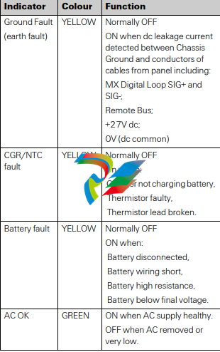
Indicator Colour Function
Ground Fault
(earth fault)
YELLOW Normally OFF
ON when dc leakage current
detected between Chassis
Ground and conductors of
cables from panel including:
MX Digital Loop SIG+ and
SIG-;
Remote Bus;
+27V dc;
0V (dc common)
CGR/NTC
fault
YELLOW Normally OFF
On when:
Charger not charging battery,
Thermistor faulty,
Thermistor lead broken.
Battery fault YELLOW Normally OFF
ON when:
Battery disconnected,
Battery wiring short,
Battery high resistance,
Battery below final voltage.
AC OK GREEN ON when AC supply healthy.
OFF when AC removed or
very low.
T
INSTALLATION, GENERAL POINTS
For MX2, ZX4, ZX4BB panels the second (auxiliary)
PSU830 is installed on top of the first (primary)
PSU830.
For MX4000 and MX4000BB, panels the auxiliary
PSU830 is installed in the battery housing. The distance between the housings is constrained by the length
of the interconnecting cables. The recommended
installation is battery housing beneath fire panel.
Connection of primary and auxiliary AC power leads is
via a distribution block supplied with kit 557.201.231.
The external AC supply is connected to a socket which is
mated with distribution block.
If FB800 fuseboard is required it may be mounted on
small chassis plate above the batteries or on top of auxiliary PSU830, if the latter then PTM800 must be
mounted on the side of the PSU830.
The PTM800 should be mounted on the top of the
PSU830 for MX4000 and MX4000BB panels. For
ZX4 and ZX4BB it can either be mounted on top or on
the left hand side with restricted access. For MX2 it
would be sited on the left hand side.
For the ZX4 and ZX4BB panels, nylon cable ties are
required to attach the distribution block to the metal
bracket inside the panel housing.
Monitoring of the auxiliary PSU830 is provided by ribbon cable connected between both power supplies.
Battery capacity must not be less than 38Ah when dual
PSU830 is used as there is possibility of overcharging
with smaller capacity batteries.
CONFIGURATION
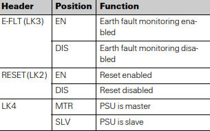
HEADERS AND LINKS
The PSU830 has three headers to which are fitted jumper
links, these headers enable selection of the following:
Earth (ground) fault monitoring, there can only be one
Earth fault monitoring circuit active at the fire panel.
Output CON3.2 +27V may be reset (turned off) under
CIE control.
Unit may be configured for single unit or dual unit operation, link selects between primary (master) and auxiliary (slave). There can only be one primary and one auxiliary connected together, no other combinations are
permitted. PSU830 cannot be mixed with any other
PSU.

Refer to Table 3, 4 and Figs. 2, 3, 4 for details of terminal
block CON3, header and wiring configurations.


