
schneiderI/A Series® Hardware Control Processor 40
The Control Processor 40 is a high-end optionally
fault-tolerant station in the Control Processor family
(CP10, CP30, CP40) that has:
• a larger memory capacity to support a greater
number of blocks
• a faster processor for increased block processing
With high performance, the CP40 is both economical
and in line with today's advancing technology. Other
members of the CP family are easily upgradable to
CP40 capabilities.
The Control Processor 40 performs regulatory, logic,
timing, and sequential control together with
connected:
• Fieldbus Modules (FBMs)
• Fieldbus Cluster I/O Cards (FBCs)
• SPECTRUM Migration Integrator I/O
• SPEC 200 Migration Integrator I/O
• SPEC 200 MICRO Migration Integrator I/O
It also performs data acquisition (via the Fieldbus
Modules), alarm detection and notification, and may
optionally serve as an interface for one or more Panel
Display Stations.
The non-fault-tolerant version of the Control
Processor 40 is a single-width processor module. The
fault-tolerant version consists of two single-width
processor modules.
Enhanced Reliability
The Control Processor 40 offers optional faulttolerance for enhanced reliability. The fault-tolerant
control processor configuration consists of two
parallel-operating modules with two separate
connections to the Nodebus and to the Fieldbus.
The two control processor modules, married together
as a fault-tolerant pair, are designed to provide
continued operation of the unit in the event of virtually
any hardware failure occurring within one module of
the pair. Both modules receive and process
information simultaneously, and faults are detected by
the modules themselves. One of the significant
methods of fault detection is comparison of
communication messages at the module external
interfaces. Upon detection of a fault, self-diagnostics
are run by both modules to determine which module
is defective. The non-defective module then assumes
control without affecting normal system operations.
To further ensure reliable communications, the faulttolerant control processor performs error detection
and address verification tests in its Nodebus and
Fieldbus interfaces.
For enhanced reliability during maintenance
operations, the Control Processor 40 is equipped with
a recessed reset button, located at the front of the
module. This feature provides for manually forcing a
module power off and on (reboot) without removing
the module from the enclosure.
Diagnostics
The Control Processor 40 uses three types of
diagnostic tests to detect and/or isolate faults:
• Power-up self-checks
• Run-time and watchdog timer checks
• Off-line diagnostics
Power-up self-checks are self-initiated when power is
applied to the control processor. These checks
perform sequential tests on the various control
processor functional elements. Red and green
indicators at the front of the control processor module
reflect the successful (or non-successful) completion
of the various phases of the control processor startup
sequence.
The run-time and watchdog timer checks provide
continuous monitoring of control processor functions
during normal system operations. The operator is
informed of a malfunction by means of printed or
displayed system messages.
Off-line diagnostics are temporarily loaded into the
system for the purpose of performing comprehensive
tests and checks on various system stations and
devices. Using the off-line diagnostics, a suspected
fault in the control processor can be isolated and/or
confirmed.
Fieldbus Modules
Fieldbus Modules provide connection of digital I/O,
analog I/O, and Intelligent Transmitters to control
processors. There are two types of Fieldbus Modules:
Main and Expansion. Some main modules can be
expanded using an expansion module.
A wide range of Fieldbus Modules is available to
perform the signal conversion necessary to interface
the control processor with field sensors and
actuators. For further information on the Fieldbus
Modules, refer to the Fieldbus Modules Product
Specification Sheet (PSS 21H-3B1 B3).
Fieldbus Flexibility
The Control Processor 40 is used in three different
Fieldbus configurations, which provide broad flexibility
in Fieldbus implementation:
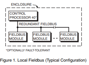
• Local Fieldbus (Figure 1) - Used only within the
enclosure, the local bus can extend up to 10 m
(30 ft). Up to 24 Fieldbus Modules (excluding
expansion modules) attach directly to the local
bus, which is redundant
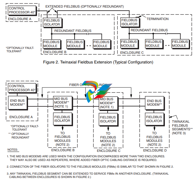
• Twinaxial (Dual-Conductor Coaxial) Fieldbus
Extension (Figure 2) - Using twinaxial cable, the
Fieldbus can optionally extend outside of the
enclosure and can be up to 1800 m (6000 ft) in
length. Up to 64 Fieldbus Modules (excluding
expansion modules) attach to the extended bus
through Fieldbus isolators. (Up to 24 Fieldbus
Modules, excluding expansion modules, can
connect to each isolator.) The twinaxial Fieldbus
extension may be redundant.
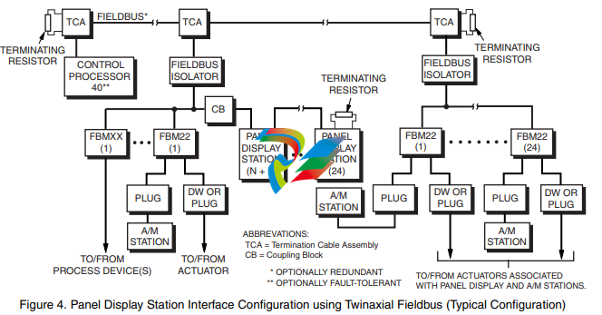
• Fiber Optic Fieldbus Extension (Figure 3) - The
fiber optic Fieldbus can optionally extend the
distance as well as add application versatility and
security. Overall Fieldbus length can be up to
20 km (12.4 mi). Like the twinaxial Fieldbus
configuration, the fiber optic Fieldbus
configuration supports up to 64 Fieldbus Modules
(excluding expansion modules), up to 24
Modules per isolator.
All three Fieldbus configurations use serial data
communication complying with Electronic Industrial
Association (EIA) Standard RS-485. The data
transmission rate is 268.75 Kbps.
Panel Display Station Interfacing
The Control Processor 40 achieves the capability to
interface Panel Display Stations when the DSI (Panel
Display Station Interface) block is selected via the
configurator. In this capacity, the Control
Processor 40 can interface up to 24 Panel Display
Stations, or a combination of Fieldbus modules
(which may include associated Auto/Manual Stations)
and Panel Display Stations mixed on the same
Fieldbus. (Note, however, that per configuration rules,
one Panel Display Station counts as two Fieldbus
Modules.)
Control strategies should be planned such that all
blocks involved with the Panel Display Station,
Auto/Manual Station, and the control loops being
monitored or controlled are in the same Control
Processor 40, and ideally in the same compound.
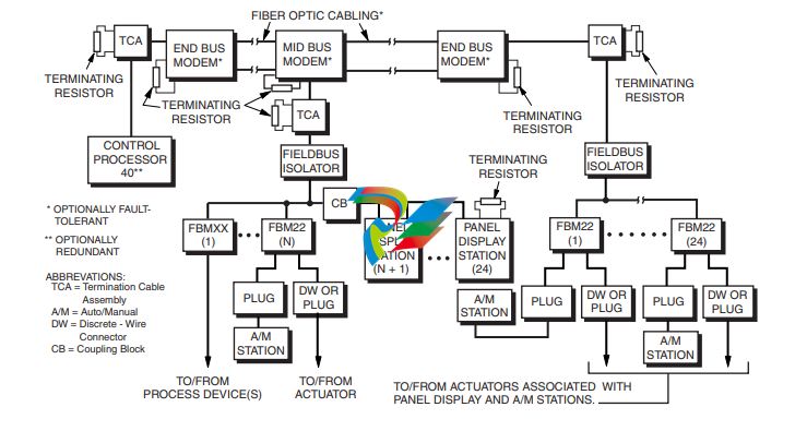
The Control Processor 40 connects to the Panel
Display Stations and Fieldbus Modules via either of
two types of Fieldbus communications media:
twinaxial cable or fiber optic cable. Figure 4 shows a
typical twinaxial Fieldbus configuration, and Figure 5
shows a typical fiber optic Fieldbus configuration.
(Refer to Fiber Optic Fieldbus Product Specification
Sheet PSS 21H-7P1 B3 for additional fiber optic
Fieldbus application information.)
Cluster I/O Subsystem Interfacing
The Control Processor 40 interfaces with the Fieldbus
Cluster Input/Output Subsystem that consists of the
Fieldbus, a multi-slot chassis configuration of a
Fieldbus Processor (FBP10), analog/digital Fieldbus
Cards (FBCs), and power supply and power monitor
card. These Cluster I/O subsystems meet the needs
of applications where a high number of channels per
card are required. Figure 6 shows a typical twinaxial
Fieldbus configuration. (Refer to the Fieldbus Cluster
I/O Subsystem PSS 21H-2T1 B3 for additional
information.)
SPECTRUM Migration Interfacing
The Control Processor 40 interfaces with a
SPECTRUM Migration Integrator subsystem via a
single or redundant I/A Series Fieldbus and a
Fieldbus Processor (FBP) with built-in FBP isolator
located within the subsystem. There are four different
FBP integrators to accommodate Unit Control
Modules (UCM), Field Input/Output Units (FIO),
Universal Field Multiplexers (UFM), and Universal
Input/Output Units (UIO).
The CP40 control strategy can include any of
following SPECTRUM configurations:
• a single SPECTRUM Migration Integrator
subsystem
• multiple types of SPECTRUM Migration
Integrator subsystems
• Fieldbus Modules (FBMs) and/or other Fieldbusbased process interface subsystems along with
the SPECTRUM Integrator subsystem(s)
Control is via the software resident in the FBP
Integrator and in the SPECTRUM I/O Equipment
Control Blocks (ECBs) operating at the CP level.
Figure 7 illustrates a typical configuration with
multiple types of Integrator subsystems with nests of
I/O cards. (Refer to PSS 21H-7Q1 B3 SPECTRUM
Migration Integrators for additional information.)
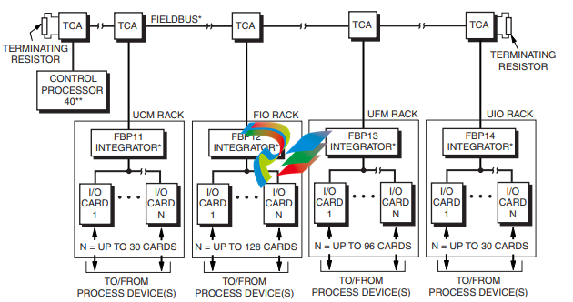
Figure 7. Twinaxial Fieldbus SPECTRUM Migration Subsystem Interface Configuration (Typical Configuration)
SPEC 200 Control Interfacing
For migration of SPEC 200 control to I/A Series
Systems, the Control Processor 40 interfaces via a
single or redundant I/A Series Fieldbus with the
SPEC 200 Control Integrator subsystem. This
subsystem consists of individual Control Integrators,
and Fieldbus Isolators attached within the SPEC 200
rack.
Control is via the software resident in the Control
Integrator and in the SPEC 200 I/O Equipment
Control Blocks (ECBs) operating at the CP level.
Figure 8 illustrates a typical configuration with
multiple Control Integrators in the SPEC 200
subsystem. (Refer to PSS 21H-7R1 B3 SPEC 200
Control Integrators for additional information.)
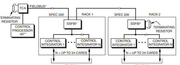
Figure 8. Twinaxial Fieldbus SPEC 200 Control Subsystem Interface Configuration (Typical Configuration)
SPEC 200 MICRO Control Interfacing
For migration of SPEC 200 MICRO control to
I/A Series systems, the Control Processor 40
interfaces via a single or redundant I/A Series
Fieldbus with the SPEC 200 MICRO Control
Integrator subsystem. This subsystem consists of
individual Control Integrators, and Fieldbus Isolators
attached within the SPEC 200 MICRO rack (NCM or
SPEC 200 2ANU).
Control is via the software resident in the Control
Integrator and in the SPEC 200 MICRO I/O
Equipment Control Blocks (ECBs) operating at the
CP level. Figure 9 illustrates a typical configuration
with multiple Control Integrators in the SPEC 200
MICRO subsystem. (Refer to PSS 21H-7R2 B3 SPEC
200 MICRO Control Integrators for additional
information.)
Control Processor 40 Upgrade
Upgrading a Control Processor 30, Control Processor
10, Tank Processor 10, or Display Processor 10 to a
CP40 involves:
• Replacing the existing Control Processor with a
CP40
• Upgrading the software license
• Modifying the System Configurator to identify the
CP40
• Loading existing compounds to the CP40
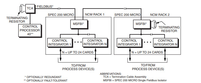
Twinaxial Fieldbus SPEC 200 MICRO Control Subsystem Interface Configuration (Typical Configuration)
Processor Type
CONTROL PROCESSOR
Microprocessor-based Intel 486DX4 (running at
100 MHz) with stored programs, using high-speed
communication capability.
NODEBUS PROCESSOR
82596CA LAN CoProcessor
FIELDBUS PROCESSOR
8344AH MicroController with serial port
Memory
SIZE
4 MB storage
ERROR DETECTION
Parity provides single-bit error detection for each
byte.
Process I/O Communications
LOCAL TWINAXIAL(A) FIELDBUS
Type
EIA RS-485
Distance
10 m (30 ft)
Transmission Rate
268.75 Kbps
EXTENDED TWINAXIAL(A) FIELDBUS(B)
Type
EIA RS-485
Distance
1800 m (6000 ft)
Transmission Rate
268.75 Kbps
FIBER OPTIC FIELDBUS(C)
Type
Optical
Distance
20 km (12.4 mi)
Transmission Rate
268.75 Kbps
Process I/O Capacity
LOCAL
24 Fieldbus Modules(D), maximum
EXTENDED
64 Fieldbus Modules(D), maximum (24 maximum on
any one Fieldbus isolator)
PANEL DISPLAY STATION INTERFACING
Up to 64 FBMs(D) or FBM equivalents (24 maximum
on any one Fieldbus isolator). One Panel Display
Station counts as two FBMs. For example, if 24
FBMs are used, only 20 Panel Display Stations may
be used.
Power Requirements
INPUT VOLTAGE (REDUNDANT VOLTAGE)
39 V dc typical
CONSUMPTION (PER NON-FAULT-TOLERANT
MODULE)
15 W, maximum
Indicators
Red and green light-emitting diodes (LEDs) indicate
operational status.
Internal Diagnostics
Self-checking performed at power-up. Runtime checks
and watchdog timer function performed during
operation.
ENVIRONMENTAL SPECIFICATIONS(A)
Operating
TEMPERATURE
0 to 60°C (32 to 140°F)
RELATIVE HUMIDITY
5 to 95% (Noncondensing)
ALTITUDE
-300 to +3,000 m (-1,000 to +10,000 ft)
Environmental Contamination Level
Class G3 (Harsh) as defined in ISA Standard S71.04
Storage
TEMPERATURE
-40 to +70°C (-40 to +158°F)
RELATIVE HUMIDITY
5 to 95% (Noncondensing)
ALTITUDE
-300 to +12,000 m (-1,000 to +40,000 ft)
PSS 21H-1B3 B3
Page 11
(A) The environmental ranges can be extended by the type of enclosure containing the module. {Refer to the applicable Product
Specification Sheet (PSS) which describes the specific enclosure that is to be used.}
PHYSICAL SPECIFICATIONS
Configuration
Single-width processor module. The fault- tolerant
version consists of two single-width processor
modules with two interconnecting buses (X-bus and
Z-bus).
Mass (Maximum)
1.7 kg (3.75 lb) for a single, non-fault-tolerant module.
Mounting
May be placed in any of the following mounting
structure slots:
– 1 X 8 Mounting Structure
– Industrial Enclosures (IE16 and IE32),
Structural Foam or Metal
– Field Enclosure 8, Structural Foam or Metal
In the fault-tolerant version, the two modules must be
mounted in adjacent mounting structure slots with the
two interconnecting buses.
-
 Hirschmann RS20-1600M2T1SDAEHH03.1.02 Rail Switch
 -
 Hirschmann BRS30-24TX Industrial Rail Switch
 -
 Hirschmann RSPM20-4T14T1EV9HHS999.9.99 Managed Ethernet Switch
 -
 Hirschmann BELDEN RS40-0009CCCCSDAPHH09.0.14 / RS400009CCCCSDAPHH09014
 -
Hirschmann RS40 Rail Switch RS40-0009CCCCSDAE
-
 Hirschmann BELDEN RS30-0802T1T1SDAP / RS300802T1T1SDAP Fully Managed Layer 2 Compact Rail Switch
 -
 Hirschmann BELDEN RS20-0800M2M2SDAUHH / RS200800M2M2SDAUHH
 -
 Hirschmann EAGLE30-04022O6TT999SCCY9HSE3F Industrial Firewall Router Switch
 -
 Hirschmann RS20-1600T1T1SDAEHH09.0.14 RS20 Rail Mount Ethernet Switch
 -
 Hirschmann EAGLE0200T1T1TDDY90000HHE05.3.03 Industrial Security Router
 -
Hirschmann - BELDEN MIPP-AD-1L9P
-
 HIRSCHMANN RSPM20-4Z64Z6TV9HHS9 942 106-999 RAIL SAFETY SWITCH
 -
 HIRSCHMANN FIBEROPTIC MODULE FIP P/N: OZDFIPG3T
 -
 HIRSCHMANN RS20-1600M2M2SDAUHH Ethernet rack-mounted switch
 -
 HIRSCHMANN BELDEN RS20-0400T1T1SDAEHH04.0.01 / RS200400T1T1SDAEHH04001
 -
HIRSCHMANN MM2-4FXM3 MICE Media Module
-
HIRSCHMANN RS20-0800M2M2SDAE Industrial Ethernet Rail Switch
-
 Hirschmann RS20-2400T1T1SDAP / RS20-2400T1T1SDAPHH05.0.02
 -
 GE MLJ1005B010H00C MLJ Digital Synchromism Check
 -
 ALSTOM MICROTECH DX21-M2 Digital Excitation Controller
 -
HIRSCHMANN BRS20-1200ZZZZ-STCY99HHSES
-
 HIRSCHMANN MM3-4FXM2 MICE Media Module
 -
Hirschmann RSB20-0800T1T1SAABHH 8Port ENet Rail Switch RSB20
-
 Hirschmann MACH102-8TP Ethernet Switch
 -
 SAACKE DDZ-M marine steam pressure atomizer
 -
 SAACKE SKV-A marine rotary cup atomizer
 -
 SAACKE Seavis HMI05e
 -
 Kollmorgen MMC-SD-2.0-230 Servo Drive 100-240VAC 2KW 10A Output 3PH 100-240VAC
 -
 Kollmorgen Servo drive CR10550
 -
 Kollmorgen AKD-P01207-NACN-0054 Servo Driver
 -
 Kollmorgen S406M-CA-036 Servostar
 -
.png) Kollmorgen AKD-B02407-NAAN-0000 Digital Servo Drive
Kollmorgen AKD-B02407-NAAN-0000 Digital Servo Drive -
 Kollmorgen SERVOSTAR S406AM-CA Digital Servo Drive
 -
 KOLLMORGEN SERVOSTAR 603-AS SERVO AMPLIFIER_SERVOSTAR603AS_S60301
 -
Kollmorgen S700 Servo Controller (S70602-NANANA-NA)
-
 Kollmorgen MPK411 controller
 -
 KOLLMORGEN MMC-SD-1.3-460-D Smart Drive
 -
 KOLLMORGEN AKM21C-CKB2AA-00 / AKM21CCKB2AA00 Servomotor
 -
 BECKHOFF AX5106-0000-0200 | Digital Compact Servo Drives 1-channel
 -
 BECKHOFF C3620-0000 INDUSTRIAL COMPUTER (MOTORSHELVES)
 -
 Beckhoff EK1960-0000 TwinSAFE Compact Controller
 -
 Beckhoff C6930-0050 Control Cabinet Industrial PC
 -
 Beckhoff CP7711-0001-0030 Industrial Computer Detection
 -
 Beckhoff CX1001-0111 Embedded PC CPU Module
 -
 Beckhoff C6017-0020 | Ultra-compact Industrial PC
 -
 Beckhoff EK1322 | 2-port EtherCAT P junction with feed-in
 -
 Beckhoff CP2219-0010 Panel
 -
 BECKHOFF C6015-0020 ULTRA COMPACT INDUSTRIAL PC
 -
 BECKHOFF CX2030-0120/Standard CPU Module Embedded PC Windows PLC controller
 -
 Beckhoff CP7721-1090-0020 Panel PC
 -
 Beckhoff PC CPU Module CX5130-0175
 -
 Beckhoff C6920-0050 Control Cabinet
 -
 Beckhoff EL6631 EtherCAT 2-Port Communication Interface, Profinet RT Controller
 -
 Beckhoff CP6202-0001-0060 touch screen panel PC
 -
 Beckhoff CP3916-1002-0000 Multi-Touch Control Panel
 -
 Beckhoff EP1809-0021 | EtherCAT Box, 16-channel digital input, 24 V DC, 3 ms, M8Preferred type
 -
 Beckhoff CX8190 PLC Embedded Industrial PC Ethernet Controller
 -
 Beckhoff CX2100-0914 Power Supply for External
 -
 Beckhoff Automation CP6906-0001-0000 HMI
 -
 Beckhoff EP7342-0002 Module
 -
 Beckhoff CX1020-0112 / CX1100-0910 / CX1020-N010 / CX1100-0003 Windows CPU
 -
 Beckhoff EP7211-0034 EtherCAT Box 1 Channel Motion Interface
 -
 Beckhoff C6240-0030 Control cabinet Industrial PC
 -
 beckhoff motherboard CB1052-0004 CB1052-0004
 -
 Beckhoff AX2006-AS Servo Drive / Variable Frequency Drive
 -
BECKHOFF CP6207-0001-0020 NSMP
-
 Beckhoff C6930-1142-0060 Industrial Computer
 -
 Beckhoff FC7501-0000 interface card
 -
 Beckhoff CX5140-0175 Embedded PC PLC CPU CX5140 Industrial Controller
 -
 Beckhoff CP7802-1100-0010: High-End IP65 Control Panel with DVI/USB Extended Interface
 -
BECKHOFF CP3716-1058-0010 CONTROL PANEL
-
 Beckhoff AX8108-0000 Single-Axis Module
 -
 Beckhoff CU8851-0000 | USB extension, USB Extended 2.0 receiver box
 -
Beckhoff C6017-0030 | Ultra-compact Industrial PC
-
 Beckhoff CX1001-0120/CX10010120.cx1000-n001.cx1000-n000 System Overview
 -
 Beckhoff CPU Module CX5140-0155/4GB CPU Module
 -
 Beckhoff CP6533-0001-005: Built-in Panel PC with High-Definition Multi-Touch Control
 -
 Beckhoff EL5042 | EtherCAT Terminal, 2-channel encoder interface, BiSS® C
 -
 Beckhoff C6920-1080-0040: Premium Control Cabinet Industrial PC
 -
 Beckhoff C6920-0060 | Control cabinet Industrial PC
 -
 Beckhoff Embedded-PC CX5010-1121
 -
 Beckhoff CB3050-0010 Mainboard Motherboard
 -
 Beckhoff PLC module CX1020-0000 Basic CPU module (service phase)
 -
 Beckhoff CP7812-1056-0010 15" Multitouch Display Control Panel
 -
 Beckhoff CX5120-0115 /2GB Controller Module
 -
 Beckhoff CP7201-1000-0000 Industrial Panel PC
 -
 Beckhoff Servo Motor AM8061-0JH1-0000
 -
 BECKHOFF CP6503-0001-0050 Built-in Panel PC
 -
Beckhoff CP3919-0010 Display G190ETN01.2 19" PCT V04. Multi-touch Control Panel
-
 Beckhoff CX5110-0112-9020/000368201 Embedded PC Intel Atom Processor
 -
 Beckhoff AX8206-0000 Dual-Axis Module
 -
Beckhoff Nail Operating Terminal CP7032-1031-0010
-
Beckhoff AM8042-0EH1-0000 Servomotor 4.10 Nm (M0), F4 (87 mm)
-
 Beckhoff EK9300 Beckhoff CPU Module
 -
Beckhoff CP3224-0020 Multitouch-Panel-PC
-
 Beckhoff CP2712-0000 12.1" 24VDC Touch Screen WMD0
 -
 BECKHOFF CX5240-0195 / 0000289234 Embedded PC 40 GB CFast Card
 -
 Beckhoff CP6932-1000-0000 Control Panel
 -
 BECKHOFF CX5120-0121 PLC Module
 -
 Beckhoff EL3218 | EtherCAT Terminal, 8-channel analog input
 -
Beckhoff C6640-0050 | Control cabinet Industrial PC
-
 Beckhoff Cx5130-0120/4GB Embedded-PC
 -
 BECKHOFF CX2030-0122 PLC PROCESSOR
 -
 BECKHOFF CX5020-0122 Controller Module
 -
 Beckhoff CP3915-0000 Multitouch Panel
 -
 BECKHOFF EL3014 | EtherCAT Terminal
 -
 BECKHOFF Industrial Computer c6920-1057-0030
 -
 Beckhoff CX5130-0141/4GB CX5130-0141 Embedded PC
 -
 Beckhoff C6240-1052-0040 4-086-06-3073 Industrial Computer
 -
 Beckhoff CX5140-0135 /4GB High-Performance Embedded Industrial PC
 -
 Beckhoff C6515-1001-0000 Industrial PC
 -
 Beckhoff AX5103-0000-0200 - Digital Compact Servo Drives
 -
 Beckhoff CX2030-0130-1003/4GB Basic CPU module
 -
 Beckhoff AX8620-0000 Power Supply Module
 -
 Beckhoff CX9020-0111 module with
 -
 Beckhoff EL7332 PLC Module
 -
 BECKHOFF CP7709-0001-0020 HMI
 -
 Beckhoff CX5120-0155/2GB Embedded PC
 -
 BECKHOFF CP7037-1037-0010 OPERATOR INTERFACE TOUCHSCREEN
 -
 Beckhoff EK9000 | ModbusTCP/UDP Bus Coupler
 -
 Beckhoff Touch Panel Screen CP6020 -0000-0000
 -
 Beckhoff CX2020-0121 Module FAST Shipping
 -
 Beckhoff CX2030-0125 Basic CPU Module
 -
 Beckhoff CP3918-0000 Multi-Touch 18.5" Control Panel
 -
 Automotion LC4A00010 DC BL Motor Control, ATS, Sub Assy, SCP, 115VAC,
 -
 500T-115VAC - VAS ENGINEERING - DORIC 500 SERIES DIGITAL TEMP INDICATOR
 -
 Honeywell X-DCS2000/EN Digital Integrated System Manager 50/60Hz 100-240V #4
 -
 Kollmorgen S60600 Servostar600 606-Fan 4 kVA, 6 A, 3 X 230 - 480 V


