schneiderI/A Series® Hardware Control Processor 40
The Control Processor 40 is a high-end optionally
fault-tolerant station in the Control Processor family
(CP10, CP30, CP40) that has:
• a larger memory capacity to support a greater
number of blocks
• a faster processor for increased block processing
With high performance, the CP40 is both economical
and in line with today's advancing technology. Other
members of the CP family are easily upgradable to
CP40 capabilities.
The Control Processor 40 performs regulatory, logic,
timing, and sequential control together with
connected:
• Fieldbus Modules (FBMs)
• Fieldbus Cluster I/O Cards (FBCs)
• SPECTRUM Migration Integrator I/O
• SPEC 200 Migration Integrator I/O
• SPEC 200 MICRO Migration Integrator I/O
It also performs data acquisition (via the Fieldbus
Modules), alarm detection and notification, and may
optionally serve as an interface for one or more Panel
Display Stations.
The non-fault-tolerant version of the Control
Processor 40 is a single-width processor module. The
fault-tolerant version consists of two single-width
processor modules.
Enhanced Reliability
The Control Processor 40 offers optional faulttolerance for enhanced reliability. The fault-tolerant
control processor configuration consists of two
parallel-operating modules with two separate
connections to the Nodebus and to the Fieldbus.
The two control processor modules, married together
as a fault-tolerant pair, are designed to provide
continued operation of the unit in the event of virtually
any hardware failure occurring within one module of
the pair. Both modules receive and process
information simultaneously, and faults are detected by
the modules themselves. One of the significant
methods of fault detection is comparison of
communication messages at the module external
interfaces. Upon detection of a fault, self-diagnostics
are run by both modules to determine which module
is defective. The non-defective module then assumes
control without affecting normal system operations.
To further ensure reliable communications, the faulttolerant control processor performs error detection
and address verification tests in its Nodebus and
Fieldbus interfaces.
For enhanced reliability during maintenance
operations, the Control Processor 40 is equipped with
a recessed reset button, located at the front of the
module. This feature provides for manually forcing a
module power off and on (reboot) without removing
the module from the enclosure.
Diagnostics
The Control Processor 40 uses three types of
diagnostic tests to detect and/or isolate faults:
• Power-up self-checks
• Run-time and watchdog timer checks
• Off-line diagnostics
Power-up self-checks are self-initiated when power is
applied to the control processor. These checks
perform sequential tests on the various control
processor functional elements. Red and green
indicators at the front of the control processor module
reflect the successful (or non-successful) completion
of the various phases of the control processor startup
sequence.
The run-time and watchdog timer checks provide
continuous monitoring of control processor functions
during normal system operations. The operator is
informed of a malfunction by means of printed or
displayed system messages.
Off-line diagnostics are temporarily loaded into the
system for the purpose of performing comprehensive
tests and checks on various system stations and
devices. Using the off-line diagnostics, a suspected
fault in the control processor can be isolated and/or
confirmed.
Fieldbus Modules
Fieldbus Modules provide connection of digital I/O,
analog I/O, and Intelligent Transmitters to control
processors. There are two types of Fieldbus Modules:
Main and Expansion. Some main modules can be
expanded using an expansion module.
A wide range of Fieldbus Modules is available to
perform the signal conversion necessary to interface
the control processor with field sensors and
actuators. For further information on the Fieldbus
Modules, refer to the Fieldbus Modules Product
Specification Sheet (PSS 21H-3B1 B3).
Fieldbus Flexibility
The Control Processor 40 is used in three different
Fieldbus configurations, which provide broad flexibility
in Fieldbus implementation:
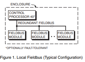
• Local Fieldbus (Figure 1) - Used only within the
enclosure, the local bus can extend up to 10 m
(30 ft). Up to 24 Fieldbus Modules (excluding
expansion modules) attach directly to the local
bus, which is redundant

• Twinaxial (Dual-Conductor Coaxial) Fieldbus
Extension (Figure 2) - Using twinaxial cable, the
Fieldbus can optionally extend outside of the
enclosure and can be up to 1800 m (6000 ft) in
length. Up to 64 Fieldbus Modules (excluding
expansion modules) attach to the extended bus
through Fieldbus isolators. (Up to 24 Fieldbus
Modules, excluding expansion modules, can


