
schneiderI/A Series® Hardware Control Processor 40
SPEC 200 2ANU).
Control is via the software resident in the Control
Integrator and in the SPEC 200 MICRO I/O
Equipment Control Blocks (ECBs) operating at the
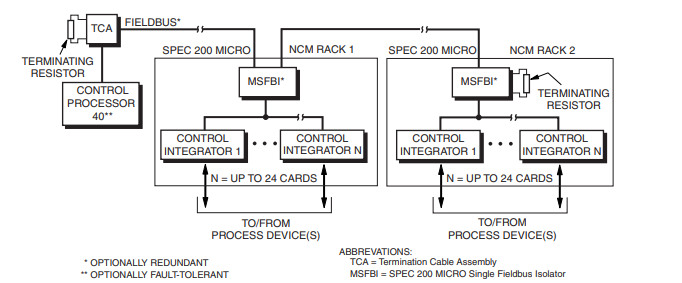
CP level. Figure 9 illustrates a typical configuration
with multiple Control Integrators in the SPEC 200
MICRO subsystem. (Refer to PSS 21H-7R2 B3 SPEC
200 MICRO Control Integrators for additional
information.)
Control Processor 40 Upgrade
Upgrading a Control Processor 30, Control Processor
10, Tank Processor 10, or Display Processor 10 to a
CP40 involves:
• Replacing the existing Control Processor with a
CP40
• Upgrading the software license
• Modifying the System Configurator to identify the
CP40
• Loading existing compounds to the CP40
Twinaxial Fieldbus SPEC 200 MICRO Control Subsystem Interface Configuration (Typical Configuration)
Processor Type
CONTROL PROCESSOR
Microprocessor-based Intel 486DX4 (running at
100 MHz) with stored programs, using high-speed
communication capability.
NODEBUS PROCESSOR
82596CA LAN CoProcessor
FIELDBUS PROCESSOR
8344AH MicroController with serial port
Memory
SIZE
4 MB storage
ERROR DETECTION
Parity provides single-bit error detection for each
byte.
Process I/O Communications
LOCAL TWINAXIAL(A) FIELDBUS
Type
EIA RS-485
Distance
10 m (30 ft)
Transmission Rate
268.75 Kbps
EXTENDED TWINAXIAL(A) FIELDBUS(B)
Type
EIA RS-485
Distance
1800 m (6000 ft)
Transmission Rate
268.75 Kbps
FIBER OPTIC FIELDBUS(C)
Type
Optical
Distance
20 km (12.4 mi)
Transmission Rate
268.75 Kbps
Process I/O Capacity
LOCAL
24 Fieldbus Modules(D), maximum
EXTENDED
64 Fieldbus Modules(D), maximum (24 maximum on
any one Fieldbus isolator)
PANEL DISPLAY STATION INTERFACING
Up to 64 FBMs(D) or FBM equivalents (24 maximum
on any one Fieldbus isolator). One Panel Display
Station counts as two FBMs. For example, if 24
FBMs are used, only 20 Panel Display Stations may
be used.
Power Requirements
INPUT VOLTAGE (REDUNDANT VOLTAGE)
39 V dc typical
CONSUMPTION (PER NON-FAULT-TOLERANT
MODULE)
15 W, maximum
Indicators
Red and green light-emitting diodes (LEDs) indicate
operational status.
Internal Diagnostics
Self-checking performed at power-up. Runtime checks
and watchdog timer function performed during
operation.
ENVIRONMENTAL SPECIFICATIONS(A)
Operating
TEMPERATURE
0 to 60°C (32 to 140°F)
RELATIVE HUMIDITY
5 to 95% (Noncondensing)
ALTITUDE
-300 to +3,000 m (-1,000 to +10,000 ft)
Environmental Contamination Level
Class G3 (Harsh) as defined in ISA Standard S71.04
Storage
TEMPERATURE
-40 to +70°C (-40 to +158°F)
RELATIVE HUMIDITY
5 to 95% (Noncondensing)
ALTITUDE
-300 to +12,000 m (-1,000 to +40,000 ft)
PSS 21H-1B3 B3
Page 11
(A) The environmental ranges can be extended by the type of enclosure containing the module. {Refer to the applicable Product
Specification Sheet (PSS) which describes the specific enclosure that is to be used.}
PHYSICAL SPECIFICATIONS
Configuration
Single-width processor module. The fault- tolerant
version consists of two single-width processor
modules with two interconnecting buses (X-bus and
Z-bus).
Mass (Maximum)
1.7 kg (3.75 lb) for a single, non-fault-tolerant module.
Mounting
May be placed in any of the following mounting
structure slots:
– 1 X 8 Mounting Structure
– Industrial Enclosures (IE16 and IE32),
Structural Foam or Metal
– Field Enclosure 8, Structural Foam or Metal
In the fault-tolerant version, the two modules must be
mounted in adjacent mounting structure slots with the
two interconnecting buses.
-
 Applied Materials (AMAT) 0190-34512 4-Channel DeviceNet Scanner Interface
 -
 Applied Materials (AMAT) 0190-34282 High-Stability Process Control Module
 -
Applied Materials (AMAT) 0190-27707 High-Precision DeviceNet I/O Controller
-
 Applied Materials (AMAT) 0190-27072 High-Performance Semiconductor Interface
 -
 AMAT 0190-24007 CPCI-3720CF Single Board Computer
 -
 AMAT 0190-23905 Spellman ESC High Voltage Power Supply
 -
 AMAT 0190-22967 High-Density Analog I/O Control Board
 -
 AMAT 0190-22543 High-Precision Analog Input/Output Module
 -
 AMAT 0190-17964 Etch DPS Interlock Module
 -
 AMAT 0190-17894 Interlock Module Conductor HART
 -
 AMAT 0190-17081 2U CompactPCI System Host Processor
 -
 AMAT 0190-16926 and 0190-16928 Based on Compact PCI
 -
AMAT 0190-15915 Intelligent I/O Control Module
-
 AMAT 0190-15840 4-Port UPA DeviceNet Interface Module
 -
 AMAT 0190-15384 Advanced Digital Signal Interface Module
 -
 AMAT 0190-14027 Wafer Flat Finder PCB
 -
 AMAT 0190-12695 SBS CL7 3U CompactPCI Single Board Computer
 -
 AMAT 0190-11817 CP3-SER16-TTL 16-Port Serial Interface Card
 -
 AMAT 0190-11524 CDN500-25 Interlock Module
 -
 AMAT 0190-07450 CompactPCI 48-Channel Digital I/O Interface Board
 -
 AMAT 0190-05990-001 Maglev Rotation System Controller (300mm)
 -
 AMAT 0190-05647 LK3710 Serial Module Transition Card
 -
 AMAT 0190-04457 High-Performance Integrated Circuit Control Module
 -
 Applied Materials (AMAT) 0190-04098 | 5.X Factory Interface I/O Distribution Board
 -
 Applied Materials (AMAT) 0190-03705 | MF Producer SE/E Interlock Module
 -
 Applied Materials (AMAT) 0190-02748 | Flex Scanner Transition Module
 -
 Applied Materials (AMAT) 0190-02362 | Mainframe Interlock 1 Relay Module
 -
 Applied Materials (AMAT) 0190-01227 | Intelligent Motor Control OMS Board
 -
 Applied Materials (AMAT) 0190-00318 | VME 486 Video Controller
 -
 Applied Materials (AMAT) 0130-14007 | Advanced RF Signal Assembly
 -
 Applied Materials (AMAT) 0130-14005 | RF Cable/Interface Assembly
 -
 Applied Materials (AMAT) 0130-01218 | High-Efficiency RF Interface Controller
 -
 Applied Materials (AMAT) 0110-77040 | Head Pneumatic Controller
 -
 Applied Materials (AMAT) 0110-00077 | Precision Control Module
 -
 AMAT 0101-57015 high-performance Next-Generation Deflection Amplifier Board
 -
 AMAT 0100-77040 critical Head Pneumatic Controller Board
 -
 AMAT 0100-76291 Data Buffer / Memory Expansion Interface
 -
 AMAT 0100-76290 Advanced I/O Interface Board
 -
 AMAT 0100-76269 Control Board / Interface Module
 -
 AMAT 0100-71462-01 high-performance Process Controller PCB
 -
 AMAT 0100-71171 Chamber Interlock Control PCB
 -
 AMAT 0100-71154 Semiconductor Circuit Board / Electronic Group Card
 -
 AMAT 0100-70034 PCB Assembly (PCBA) for Endpoint VGA I/O Interconnect.
 -
 AMAT 0100-38032 ESC (Electrostatic Chuck) Controller PCB
 -
 AMAT 0100-36035 DPS Source Match / Seriplex I/O Distribution PCB
 -
 AMAT 0100-35231 Seriplex I/O Distribution Module
 -
 AMAT 0100-35217 TC Amp Interlock PCB Module
 -
 AMAT 0100-35065 High-Precision Serial Isolator PCB
 -
 AMAT 0100-35054 Advanced Chamber Interface Module
 -
 AMAT 0100-20453 DeviceNet Digital I/O Interface Board
 -
 AMAT 0100-20100 High-Performance Semiconductor Component
 -
 AMAT 0100-20068 Precision CCD Image Control Board
 -
 AMAT 0100-20064 Advanced Semiconductor Control Module
 -
Applied Materials (AMAT) 0100-20018 Advanced Communication Interface Module
-
 Applied Materials (AMAT) 0100-20016 High-Performance Interface and Control Module
 -
 Applied Materials (AMAT) 0100-20003 Digital I/O (DI/DO) Interface Board
 -
 Applied Materials (AMAT) 0100-20001 System Electronics Interface (SEI) / PCB Assembly
 -
 Applied Materials (AMAT) 0100-11030 Chamber Hardware / Gas Distribution Component
 -
 Applied Materials (AMAT) 0100-11022 Semiconductor Board Card
 -
 Applied Materials (AMAT) 0100-11018 Advanced Interface Control Module
 -
 Applied Materials (AMAT) 0100-11001 Precision Analog Output Board
 -
 Applied Materials (AMAT) 0100-11000 High-Precision Analog Input Board
 -
 Applied Materials (AMAT) 0100-09237 Advanced Signal Interface Module
 -
 Applied Materials (AMAT) 0100-09204 Advanced Digital Interface Control Board
 -
 Applied Materials (AMAT) 0100-09172 High-Density Digital I/O Control Board
 -
 Applied Materials (AMAT) 0100-09137 High-Performance VME Control Module
 -
 Applied Materials (AMAT) 0100-09054 Precision Analog Input Board
 -
 Applied Materials (AMAT) 0100-09029 Turbo Interconnect Interface Module
 -
 AMAT 0100-03391 Precision Semiconductor Control
 -
 AMAT 0100-01984 | VME System Interface & Logic Controller Board
 -
 AMAT 0100-01363 | VME Intelligent System Control & I/O Board
 -
 AMAT 0100-01321 | VME DeviceNet Scanner / Interface Board
 -
AMAT 0100-00793 | VME Multi-Channel Interface & Logic Board
-
 AMAT 0100-00689 | VME PCB Power Module
 -
 AMAT 0100-00580 | VME Intelligent System Controller Board
 -
 AMAT 0100-00523 | VME Multi-Channel Analog-to-Digital (A/D) Board
 -
 AMAT 0100-00493 | VME Multi-Function System Controller Board
 -
 AMAT 0100-00398 | VME Interface System Control Board
 -
 AMAT 0100-00369 | VME 12-Channel High-Speed Stepper Motor Controller
 -
 AMAT 0100-00196 | VME System Mainframe CPU Controller Board
 -
 AMAT 0100-00169 | VME 12-Channel Stepper Motor Controller Board
 -
 AMAT 0100-00162 | VME Dual Channel Serial Communication Board
 -
 AMAT 0100-00137 | VME Stepper Motor Controller Interface Board
 -
 AMAT 0100-00075 | VME Digital Input/Output (DI/O) Interface Board
 -
 AMAT 0100-00007 VME Analog Input/Output Interface Board
 -
 AMAT 0100-00002 | VME Slave I/O Interface PCB
 -
 AMAT 0090-05596 High-Voltage DC Power Cable Assembly
 -
 AMAT 0090-01809 | High-Performance RF Power Cable Assembly
 -
 AMAT 0010-29958 | CCM HART 3 Mainframe Control Assembly
 -
 AMAT 0010-20003 System Controller Card Cage Assembly
 -
.png) AMAT 0010-11239 PVD High-Voltage Power Interface Assembly
AMAT 0010-11239 PVD High-Voltage Power Interface Assembly -
 AMAT 0010-09416 RF Matching Network Assembly
 -
 AMAT 0010-00019 Analog Power Supply Assembly
 -
 AMAT AS00009-02 (31-000-00940) | Precision Semiconductor Component
 -
 AMAT 0010-00028 Power Supply Module
 -
 AMAT 0330-1586A Serial Communication PCB
 -
 AMAT 0190-09690 Seriplex SENSORbus SPX-MUXADIO-001
 -
 AMAT 0190-04397 DeviceNet I/O Interface Board
 -
 AMAT 0190-02506 DeviceNet I/O Interface Card
 -
 AMAT 0090-00475 Seriplex 210 MUXADIO
 -
 AMAT 410-0198-1 Multi-Output Switching Power Supply
 -
 AMAT 0100-20458 high-reliability Configurable Interlock Personality Board
 -
 AMAT VAS104350-0415 Gasline Heater Control Unit
 -
 AMAT VME6U1V2 VMEbus Backplane Interface Module
 -
AMAT 0920-01070 high-performance RF Power Generator
-
 AMAT 0090-76133A VME Single Board Computer (SBC)
 -
 AMAT 0190-24115 DeviceNet I/O Interface Card
 -
 AMAT 0190-37607 Backplane / Base Board Assembly
 -
 AMAT 0190-32372 Analog Input/Output (I/O) Board
 -
 AMAT 0190-09956 Loadlock Interface PCB Base Assembly
 -
 AMAT 0190-07908 four-channel DeviceNet Interface Card
 -
 AMAT 0190-07905 (UPS) control board
 -
 AMAT 0190-07502 Precision Controller / Interface Board
 -
 AMAT 0190-03680 I/O Backplane
 -
 AMAT 0190-02200 Water Leak Detection Control Board
 -
 AMAT 0100-76124 Digital I/O Board Assembly
 -
 AMAT 0100-35563 Leak Detector Configuration PCB
 -
 AMAT 0100-35250 Chamber Interface DPS Centura PCB
 -
 AMAT 0100-35124 Seriplex I/O Distribution Board
 -
 AMAT 0100-35058 Loadlock Interlocks PCB
 -
 AMAT 0100-20213 RF Match Detector PCB
 -
 AMAT 0100-20063 Interface PCB Assembly
 -
 AMAT 0100-09225 TC AMP/INTERLOCK PCB
 -
 AMAT 0100-09153 Gas Panel Interface PCB
 -
 AMAT 0100-09127 Loader Interconnect Board
 -
 AMAT 0100-09009 Buffer I/O PCB Card
 -
 AMAT 0100-02813 Signal Conditioning Board
 -
 AMAT 0100-01911 AC Gas Heater Control Board


