
GEPPCBug Firmware Package User’s Manual Parts 1 & 2
Notice
While reasonable efforts have been made to assure the accuracy of this document,
Motorola, Inc. assumes no liability resulting from any omissions in this document,
or from the use of the information obtained therein. Motorola reserves the right to
revise this document and to make changes from time to time in the content hereof
without obligation of Motorola to notify any person of such revision or changes.
No part of this material may be reproduced or copied in any tangible medium, or
stored in a retrieval system, or transmitted in any form, or by any means, radio,
electronic, mechanical, photocopying, recording or facsimile, or otherwise,
without the prior written permission of Motorola, Inc.
It is possible that this publication may contain reference to, or information about
Motorola products (machines and programs), programming, or services that are
not announced in your country. Such references or information must not be
construed to mean that Motorola intends to announce such Motorola products,
programming, or services in your country.
Restricted Rights Legend
If the documentation contained herein is supplied, directly or indirectly, to the U.S.
Government, the following notice shall apply unless otherwise agreed to in
writing by Motorola, Inc.
Use, duplication, or disclosure by the Government is subject to restrictions as set
forth in subparagraph (c)(1)(ii) of the Rights in Technical Data and Computer
Software clause at DFARS 252.227-7013.
Motorola, Inc.
Computer Group
2900 South Diablo Way
Tempe, Arizona 85282
Preface
The PPCBug Firmware Package User’s Manual provides information on the PPCBug
firmware, the start-up and boot routines, the debugger commands, the one-line
assembler/disassembler, and the debugger system calls. All information
contained herein is specific to Motorola’s PowerPC™-based boards: MVME230x
VME Processor Modules, MVME260x Single Board Computers, MVME3604 VME
Processor Modules, MVME4604 VME Dual Processor Modules, MTX Embedded
ATX Motherboards, MCP750 CompactPCI, and PMCspan PCI expansion boards.
In this manual, they are collectively referred to as the PowerPC board or board.
This manual covers release 3.5, and earlier versions, of PPC1Bug.
This document is bound in two parts. Part 1 (PPCBUGA1/UM4) contains the Table
of Contents, List of Figures, List of Tables, and Chapters 1 through 3. Part 2
(PPCBUGA2/UM4) contains Chapters 4 and 5, Appendixes A through H, and the
Index.
The diagnostics are covered in the PPCBug Diagnostics Manual (PPCDIAA/UM2).
A basic knowledge of computers and digital logic is assumed. Refer to Appendix
A, Related Documentation, of this manual for a list of documents that may provide
helpful information.
This manual is intended for anyone who designs OEM systems, supplies
additional capability to an existing compatible system, or works in a lab
environment for experimental purposes.
Motorola® and the Motorola symbol are registered trademarks of Motorola, Inc.
PowerPC™ is a trademark of IBM, and is used by Motorola with permission.
AIXTM is a trademark of IBM Corp.
All other products mentioned in this document are trademarks or registered
trademarks of their respective holders.
Conventions
The following conventions are used in this document:
bold
is used for user input that you type just as it appears. Bold is also used for
commands, options and arguments to commands, and names of programs,
directories, and files.
italic
is used for names of variables to which you assign values. Italic is also used
for comments in screen displays and examples.
courier
is used for system output (e.g., screen displays, reports), examples, and
system prompts.
Return or ‘the Return key’
represents the Enter, Return, or Carriage Return key.
CTRL
represents the Control key. Execute control characters by pressing the
CTRL key and the letter simultaneously, e.g., CTRL-d.
|
Separates two or more items that you can select from (one only).
[ ]
encloses an optional item that may occur zero or one time.
{ }
encloses an optional item that may occur zero or more times.
A character precedes a data or address parameter to specify the numeric format,
as follows (if not specified, the format is hexadecimal):
$ dollar a hexadecimal character.
0x Zero-x
% percent a binary number.
& ampersand a decimal number.
Safety Summary
Safety Depends On You
The following general safety precautions must be observed during all phases of operation, service, and
repair of this equipment. Failure to comply with these precautions or with specific warnings elsewhere in
this manual violates safety standards of design, manufacture, and intended use of the equipment.
Motorola, Inc. assumes no liability for the customer's failure to comply with these requirements.
The safety precautions listed below represent warnings of certain dangers of which Motorola is aware. You,
as the user of the product, should follow these warnings and all other safety precautions necessary for the
safe operation of the equipment in your operating environment.
Ground the Instrument.
To minimize shock hazard, the equipment chassis and enclosure must be connected to an electrical ground.
The equipment is supplied with a three-conductor ac power cable. The power cable must be plugged into
an approved three-contact electrical outlet. The power jack and mating plug of the power cable meet
International Electrotechnical Commission (IEC) safety standards.
Do Not Operate in an Explosive Atmosphere.
Do not operate the equipment in the presence of flammable gases or fumes. Operation of any electrical
equipment in such an environment constitutes a definite safety hazard.
Keep Away From Live Circuits.
Operating personnel must not remove equipment covers. Only Factory Authorized Service Personnel or
other qualified maintenance personnel may remove equipment covers for internal subassembly or
component replacement or any internal adjustment. Do not replace components with power cable
connected. Under certain conditions, dangerous voltages may exist even with the power cable removed. To
avoid injuries, always disconnect power and discharge circuits before touching them.
Do Not Service or Adjust Alone.
Do not attempt internal service or adjustment unless another person capable of rendering first aid and
resuscitation is present.
Use Caution When Exposing or Handling the CRT.
Breakage of the Cathode-Ray Tube (CRT) causes a high-velocity scattering of glass fragments (implosion).
To prevent CRT implosion, avoid rough handling or jarring of the equipment. Handling of the CRT should
be done only by qualified maintenance personnel using approved safety mask and gloves.
Do Not Substitute Parts or Modify Equipment.
Because of the danger of introducing additional hazards, do not install substitute parts or perform any
unauthorized modification of the equipment. Contact your local Motorola representative for service and
repair to ensure that safety features are maintained.
Dangerous Procedure Warnings.
Warnings, such as the example below, precede potentially dangerous procedures throughout this manual.
Instructions contained in the warnings must be followed. You should also employ all other safety
precautions which you deem necessary for the operation of the equipment in your operating environment.
!
WARNING
Dangerous voltages, capable of causing death, are present in this
equipment. Use extreme caution when handling, testing, and
adjusting.
The computer programs stored in the Read Only Memory of this device contain
material copyrighted by Motorola Inc., 1995, 1996, and 1997, and may be used only
under a license such as those contained in Motorola’s software licenses.
The software described herein and the documentation appearing herein are
furnished under a license agreement and may be used and/or disclosed only in
accordance with the terms of the agreement.
The software and documentation are copyrighted materials. Making unauthorized
copies is prohibited by law. No part of the software or documentation may be
reproduced, transmitted, transcribed, stored in a retrieval system, or translated
into any language or computer language, in any form or by any means without the
prior written permission of Motorola, Inc.
Disclaimer of Warranty
Unless otherwise provided by written agreement with Motorola, Inc., the software
and the documentation are provided on an “as is” basis and without warranty.
This disclaimer of warranty is in lieu of all warranties whether express, implied, or
statutory, including implied warranties of merchantability or fitness for any
particular purpose.
!
WARNING
This equipment generates, uses, and can radiate electromagnetic energy. It may cause or be susceptible to electromagnetic interference (EMI) if not installed and used in a
cabinet with adequate EMI protection.
© Copyright Motorola, Inc. 1996, 1997
All Rights Reserved
Printed in the United States of America
December 1997
PPCBug Overview
PPCBug is a powerful evaluation and debugging tool for systems
built around the Motorola PowerPC microprocessors. PPCBug
firmware consists of three parts:
❏ Command-driven user-interactive software debugger. It is
hereafter referred to as the debugger, which is described in this
manual. Debugging commands are available for loading and
executing user programs under complete operator control for
system evaluation.
❏ Command-driven diagnostic package for testing and
troubleshooting the PowerPC board, which is hereafter called
the diagnostics. Refer to the PPC1Bug Diagnostics Manual.for
information on the diagnostics and the diagnostics utilities
and self-tests.
❏ MPU, firmware, and hardware initialization routines, which
are described in this manual.
The PPCBug firmware is implemented on the following Motorola
PowerPC-based products:
❏ MVME230x VME Processor Modules
❏ MVME260x Single Board Computers
❏ MVME3604 VME Processor Modules
❏ MVME4604 VME Dual Processor Modules
❏ MTX Embedded ATX Motherboards
❏ MCP750 PowerPC Single Board Computers
A PMCspan board added to any of these also interfaces with PPCBug.
They are collectively referred to in this manual as the PowerPC board
or board.
The debugger includes:
❏ Commands for display and modification of memory
❏ Breakpoint and tracing capabilities
❏ Assembler and disassembler useful for patching programs
Various PPCBug routines that handle I/O, data conversion, and
string functions are available to user programs through the System
Call handler.
Because PPCBug is command-driven, it performs its various
operations in response to user commands entered at the keyboard.
Comparison with other Motorola Bugs
The PPCBug is similar to previous Motorola firmware packages
(e.g., MVME147Bug, MVME167Bug, MVME187Bug), with
differences due to microprocessor architectures. These differences
are primarily reflected in the instruction mnemonics, register
displays, addressing modes of the assembler/disassembler, and
argument passing to the system calls.
PPCBug Implementation
PPCBug is written largely in the C programming language,
providing benefits of portability and maintainability. Where
necessary, the assembly language has been used in separately
compiled program modules that deal with processor-specific
issues. No mixed-language modules are used.
Physically, PPCBug is contained in two socketed 32-pin PLCC
Flash devices that together provide 1MB (256KB words) of storage.
PPCBug uses the entire memory contained in the two devices.
The executable code is checksummed at every power-on or reset
firmware entry. The result is checked with a pre-calculated
checksum contained in the last 16-bit word of the Flash image.
!
Caution
Although a command to allow the erasing and
reprogramming of this Flash memory is available to
you, keep in mind that reprogramming any portion of
Flash memory will erase everything currently contained
in Flash, including PPCBug.
Memory Requirements
The debugger requires approximately 768KB of read/write
memory (i.e., DRAM). The debugger will allocate this memory
from the top of memory. For example, on a system which contains
64MB ($04000000) of read/write memory, the debugger's memory
page will be located at $03F80000 to $03FFFFFF.
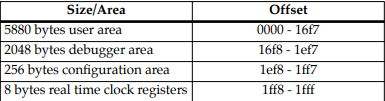
Size and Address Requirements for NVRAM
Currently, Motorola uses the SGS-Thompson Timekeeper SRAM
device (48T559), or equivalent. This is used on the PowerPlus
boards and is structured by the Debugger as follows:
NVRAM = 8192 bytes total size (with rtc)
Address ranges include:
Set-up
Refer to the board installation and use manual for information on
installing the hardware, configuring jumpers, and assigning the
console monitor.
Start-up
At either power-up or system reset, PPCBug performs the MPU,
hardware, and firmware initialization process (refer to MPU,
Hardware, and Firmware Initialization on page 1-5). This process
includes a checksum of the FLASH memory contents.
The following types of messages are displayed on the firmware
console during the initialization process:
Copyright Motorola Inc. 1988 - 1997, All Rights Reserved
PPC1 Debugger/Diagnostics Release Version 3.x - xx/xx/xx/RMxx
COLDStart
Local Memory Found =04000000 (&67108864)
MPU Clock Speed =167Mhz
BUS Clock Speed =67Mhz
Reset Vector Location : ROM Bank B
Mezzanine Configuration: Single-MPU
Current 60X-Bus Master : MPU0
Idle MPU(s) : NONE
System Memory: 64MB, ECC Enabled (ECC-Memory Detected)
L2 Cache: NONE
PPC1-Bug>
At this point, PPCBug is waiting for you to enter one of the
commands described in Chapter 3 of this manual.
PPCBug may alternatively be configured via the ENV command to
run selftest and/or autoboot automatically during startup. If so,
then PPCBug will instead behave as follows:
The system pauses five seconds, during which you may terminate
start-up, and exit to the diagnostics prompt, by pressing ESC or the
Break key
The system performs the self test diagnostics if you do not
terminate system start-up. Upon successful completion of these
tests, the system pauses another five seconds. You may terminate
start-up, and exit to the diagnostics prompt, by pressing ESC or the
Break key.
If you do not terminate system start-up, the system begins the boot
routine that has been set up in the ENV command, either NVRAM
Boot List Boot, Auto Boot, ROMboot, or Network Auto Boot.
If the self-tests fail, various error messages appear, and the
diagnostics prompt appears.
Refer to Chapter 3 for information on setting the ENV command
parameters.
MPU, Hardware, and Firmware Initialization
The MPU, hardware, and firmware initialization process is
performed by the PPCBug power-up or system reset. The steps
below are a high-level outline; not all of the detailed steps are listed.
1. Set MPU.MSR to known value.
2. Invalidate the MPU's data/instruction caches.
3. Clear all segment registers of the MPU.
4. Clear all block address translation registers of the MPU.
5. For “dual CPU only” boards (MVME460x or MTX), catch one
CPU of a dual CPU and place it in a waiting loop.
6. Initialize the MPU bus to PCI bus bridge device.
7. Initialize the PCI bus to ISA bus bridge device.
8. Calculate the external bus clock speed of the MPU.
9. Delay for 750 milliseconds.
10. Determine the CPU board type.
11. Size the local read/write memory (i.e., DRAM).
12. Initialize the read/write memory controller
13. Set base address of memory to $00000000.
14. Retrieve the speed of read/write memory from NVRAM.
15. Initialize read/write memory controller with the speed of
read/write memory.
16. Retrieve the speed of read only memory (i.e., FLASH) from
NVRAM.
17. Initialize read only memory controller with the speed of read
only memory.
18. Enable the MPU's instruction cache.
19. Copy the MPU's exception vector table from $FFF00000 to
$00000000.
20. Initialize the SIO (PC87303/PC87307/PC87308) resources'
base addresses for boards that have the SIO device.
21. Initialize the Z8536 device if the board has the device.
22. Verify MPU type.
23. Enable the super-scalar feature of the MPU (boards with
MPC604-type chips only).
24. Initialize the Keyboard Controller
(PC87303/PC87307/PC87308) for boards that have the
device.
25. Determine the debugger's Console/Host ports, and initialize
the appropriate UART and Graphic devices.
26. Display the debugger's copyright message.
27. Display any hardware initialization errors that may have
occurred.
28. Checksum the debugger object, and display a warning
message if the checksum failed to verify.
29. Display the amount of local read/write memory found.
30. Verify the configuration data that is resident in NVRAM,
and display a warning message if the verification failed.
31. Calculate and display the MPU clock speed. Verify that the
MPU clock speed matches the configuration data, and
display a warning message if the verification fails.
32. Display the BUS clock speed. Verify that the BUS clock speed
matches the configuration data, and display a warning
message if the verification fails.
33. For boards that have a Keyboard Controller display
initialization errors that have occurred.
34. Probe PCI bus for supported Network devices.
35. Probe PCI bus for supported Mass Storage devices.
36. Initialize the memory/IO addresses for the supported PCI
bus devices.
37. Execute self-test, if configured.
38. Extinguish the board fail LED, if there are no self-test failures
or initialization/configuration errors.
39. Execute the configured boot routine, either ROMboot,
Autoboot, or Network Autoboot. (PowerPlus architecture
boards do not execute a configured boot routine.)
40. Execute the user interface (i.e., the PPC1-Bug> or
PPC1-Diag> prompt).
LED/Serial Startup Diagnostic Codes
These codes are displayed on seven-segment LEDs at key points in
the initialization of the hardware devices. Should the debugger fail
to come up to a prompt, the last code displayed will indicate how
far the initialization sequence had progressed before stalling. The
serial port version of the startup codes is enabled by an ENV
parameter:
Serial Startup Code Master Enable [Y/N]=N?
Under normal conditions, the startup sequence begins at 0x1100
and continues to the PPC1-Bug> prompt just after 0x11D4. RAM
initialization problems may cause the startup sequence to terminate
at the : (RawBug) prompt just after 0x11D8 instead.
The operating system boot sequence begins at 0x11E0 with the
creation of residual data and continues to 0x11EC just before
execution is passed to the boot image. The OS may have its own
LED codes which are displayed after 0x11EC.
A line feed can be inserted after each serial code is displayed to
prevent it from being overwritten by the next code. This is also
enabled by an ENV parameter:
Serial Startup Code LF Enable [Y/N]=N?
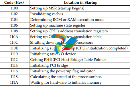
The following firmware codes are always sent to 7-segment LEDs
located at ISA I/O address 0x8C0. These codes can also be sent to
the debugger serial port if the ENV parameter “Serial Startup Code
Master Enable” is set to ‘Y’. The list of LED/serial codes follows.
Table 1-1. LED/Serial Startup Diagnostic Codes
-
 HIRSCHMANN MSM20-M2M2M2M2SY9HH9E Ethernet media modul
 -
 HIRSCHMANN SPIDER-PL-20-05T1999999TWVHHHH Industrial Ethernet Rail Switch
 -
 Hirschmann SPIDER-PL-20-07T1M2M299TWVHHHH Industrial ETHERNET Rail Switch
 -
.png) Hirschmann (Belden) RS20-1600M2M2SDAEHC09.1.00 DIN-rail managed industrial Fast Ethernet switch
Hirschmann (Belden) RS20-1600M2M2SDAEHC09.1.00 DIN-rail managed industrial Fast Ethernet switch -
 Hirschmann (Belden) RS30-1602O6O6TDAPHC09.1.00 DIN-rail managed industrial Ethernet switch
 -
 Hirschmann (Belden) RS30-2402O6T1SDAPHH09.0.13 DIN-rail industrial Ethernet switch
 -
Hirschmann (Belden) SPIDER-PL-20-04T1S29999TY9HHHH Ethernet DIN-rail switch
-
 HIRSCHMANN RS20-1600T1T1SDAUHX Switch
 -
 HIRSCHMANN BRS42-0012OOOO-SPCZ99HHSES industrial switch
 -
 Hirschmann RS20-0800S2S2TDHPHH09.0.14 Fast Ethernet DIN rail switch.
 -
 HIRSCHMANN MM20-Z6Z6M2M2SAHH Hybrid Fast Ethernet Media Module
 -
 HIRSCHMANN MM20-Z6Z6T1T1SAHH hot-swappable hybrid Fast Ethernet Media Module
 -
 HIRSCHMANN MM20-P9P9T1T1SAHH Hybrid Fast Ethernet Media Module
 -
 HIRSCHMANN MM20-M4T1T1T1SAHH Hybrid Fast Ethernet Media Module
 -
 HIRSCHMANN MM20-M4M4T1T1SAHH Hybrid Fast Ethernet Media Module
 -
 HIRSCHMANN MM20-M2M2M2M2SZHH Ethernet media module
 -
HIRSCHMANN MM20-M2M2M2M2SAHH Ethernet media module
-
 HIRSCHMANN MM20-T1T1T1T1EBH 4-port Fast Ethernet Copper Cable Media Module
 -
HIRSCHMANN MM20-T1T1T1T1SAHH 4-port Fast Ethernet Copper Cable Media Module
-
HIRSCHMANN MM20-T1T1T1T1SAHH 4-port Fast Ethernet Copper Cable Media Module
-
 HIRSCHMANN MM20-Z6Z6EBH Hot-swappable fast Ethernet media module
 -
 HIRSCHMANN MM20-Z6Z6SAHH Ethernet media module
 -
HIRSCHMANN MM20-Z6Z6Z6Z6EBH Industrial Media Module
-
 MSM40-T1T1T1TZ9HH9E99.9.99 HIRSCHMANN Switch
 -
 HIRSCHMANN MS20-0800SAAEHC / MS20-0800SAAEHC0 8-port modular Layer 2 management Ethernet switch
 -
 Hirschmann RSPM20-4T14T1SZ9HHS9 Switch RSPM20-4T14T1SZ9HHS9
 -
 HIRSCHMANN RS20-1600M2M2SDAEHH09.1. RS20/30/40 Managed Switch configurator
 -
HIRSCHMANN RS20-1600M2M2SDAEHX09.0.00 Ethernet switch
-
 HIRSCHMANN BELDEN SPIDER-PL-20-07T1M2M299TY9HHHH / SPIDERPL2007T1M2M299TY9HHHH
 -
HIRSCHMANN MM3-1FXS2/3TX1 Switching Board Module
-
 HIRSCHMANN RSPE30-24044O7T99-ECCP999HHSE2A08.1.00 Industrial-grade fanless management-type Ethernet switch
 -
 HIRSCHMANN RS30-1602OOZZSDAEHC09.1.00 DIN-rail-mounted managed Layer 2 Ethernet switch
 -
 HIRSCHMANN MACH104-20TX-F Managed 24-port Full Gigabit 19" Switch
 -
 HIRSCHMANN Switch RS20-0800M4M4SDAE
 -
Hirschmann RS30-1602O6O6SDAEHH09.1. Management-type Ethernet switch
-
 Hirschmann RS30-1602OOZZSDAEHC09.0.10 Open rack-style Ethernet switch
 -
 HIRSCHMANN RSPE30-24044O7T99-SCCV999HHSI2SXX.X.XX High-Availability Seamless Redundancy
 -
HIRSCHMANN RSPE30-24044O7T99-SCCZ999HHSE2A DIN-rail Ethernet switch
-
HIRSCHMANN MM2-4TX1-EEC switch
-
HIRSCHMANN MSM40-T1T1T1T1TZ9HH9E99.9.99 Module
-
 HIRSCHMANN RS20 Rail Switch RS20-0400S4T1SDAEHC07.1.01
 -
 HIRSCHMANN M4-FAST8-SFP Fast Ethernet media module
 -
 HIRSCHMANN RS20-0400M2T1SDAP Managed Fast-Ethernet-Switch
 -
 HIRSCHMANN BELDEN SPIDER II 8TX/1FX EEC Industrial Ethernet Rail Switch
 -
HIRSCHMANN MM3-2FXS2/2TX1
-
 HIRSCHMANN RS2-4TX/1FX EEC Industrial Ethernet Rail Switch
 -
 RS30-0802O6O6SDAEHC09.0.10 HIRSCHMANN Switch
 -
 HIRSCHMANN m4-8TP-RJ45 Ethernet Media Module
 -
 HIRSCHMANN MSP30-24040SCZ9URHHE3A switch
 -
 Hirschmann rack MS30-1602SAAPHC
 -
 HIRSCHMANN RS2-FX/FX Industrial Switch Module
 -
Rs1txfx - Hirschmann - Rs1-Tx/Fx Rail Switch
-
RS20-0800S2S2SDAEHC09.1.00 HIRSCHMANN Commutator
-
 Hirschmann EAGLE20 TX/TX Industrial Security Router
 -
 Hirschmann SPIDER-SL-20-04T1S29999SY9HHHH Industrial Switch
 -
 HIRSCHMANN MAR1040-4C4C4C4C9999SMMHRHHXX.X. Gigabit Ethernet Switch configurator
 -
 Hirschmann MAR1040 Industrial Switch
 -
 HIRSCHMANN BELDEN RS30-1602O6O6SDAE
 -
Hirschmann RS20-1600M2M2SDAUHC Ethernet DIN rail switch
-
 HIRSCHMANN OCTOPUS 24M industrial switch
 -
 HIRSCHMANN RS20-1600T1T1SDAE Management-type Ethernet switch
 -
 HIRSCHMANN RS20-1600T1T1SDAUHH industrial switch
 -
HIRSCHMANN RS20-0800M2M2SDAPHC09.0.04 switch
-
 Hirschmann MR 8-03 24V DC Industrial Modular Bridge/Router
 -
 HIRSCHMANN RS20-0400M2T1SDAPHC08.0.01 Managed Switch
 -
 MACH1130 Hirschmann Industrial Switch
 -
 HIRSCHMANN 943824-002 SPIDER 5TX Industrial Ethernet Switch
 -
 HIRSCHMANN RS30-0802O6O6SDAEHC09.1.00 Managed Industrial Switch
 -
 HIRSCHMANN RS20-0400M2M2TDAEHC04.0.01 Industrial Switch
 -
 HIRSCHMANN BRS20-0600Z6Z6-STCZ99HHSES Industrial Switch
 -
 HIRSCHMANN MACH104-20TX-FR-L3P Industrial Ethernet Switch
 -
 HIRSCHMANN RS40-0009CCCCEDBPHH06.0.01 Industrial Switch
 -
 HIRSCHMANN RS2-3TX/2FX EEC Industrial Ethernet Switch
 -
 Hirschmann MACH 1020/1030 Fast/Gigabit Rack Mount Switches
 -
HIRSCHMANN RS20-0800M2M2SDAPHC09.0.14 Industrial Switch
-
 HIRSCHMANN RS20-1600T1T1SDAEHC09.0.04 Industrial Switch
 -
 HIRSCHMANN RSB20-0800T1T1EAABHH Industrial Switch
 -
 HIRSCHMANN MACH4002-48+4G-L3E Industrial Backbone Switch
 -
 HIRSCHMANN RS20-0400S2T1SDAE Industrial Managed Switch
 -
HIRSCHMANN RS20-0800S2T1SDAUHC Industrial Switch
-
 HIRSCHMANN RS20-2400S4S4SDAEHC09.0.14 industrial switch
 -
 HIRSCHMANN OS20-001200T5T5T5- TBBZ999HHNE3S 08.1.00 industrial switch
 -
HIRSCHMANN OS20-001200T5T5T5- TBBZ999HHNE3S 08.1.00 industrial switch
-
 HIRSCHMANN RS40-0009CCCCSDAEHH09.0.14 switch
 -
 Hirschmann RS20-1600T1T1SDAUHC Management-type Ethernet Switch
 -
 Hirschmann M1-8SFP Switche
 -
Hirschmann Industrial Ethernet Ruggedized Switch MACH1000 Family
-
 Basler Electric, Solid State Protective Relay, BE1-60
 -
BASLER ELECTRIC SR4A-2B15B3A Static Voltage Regulator
-
.png) BASLER ELECTRIC EXCITER DIODE MONITOR EDM-200
BASLER ELECTRIC EXCITER DIODE MONITOR EDM-200 -
.png) BASLER ELECTRIC DECS125-15-B2C5 DIGITAL EXCITATION CONTROL SYSTEM V 2.0.9
BASLER ELECTRIC DECS125-15-B2C5 DIGITAL EXCITATION CONTROL SYSTEM V 2.0.9 -
 BASLER ELECTRIC BE1-851 OVERCURRENT PROTECTION RELAY MECHANISM
 -
 Basler Electric BE1-51A / BE151A
 -
 Basler Electric BE1-40Q Loss of Excitation Relay
 -
 Basler Electric BE1-87G Variable Percentage Differential Relay
 -
 Basler Electric BE1-11 Protection System I5A3M2P2N0EA00
 -
 BASLER ELECTRIC DECS-200-1C Digital Excitation Control System
 -
 Basler Electric / Kohler BE1-11g Generator Protection Relay G5A3M2J2N0E000
 -
BASLER ELECTRIC DECS125-15 DIGITAL EXCITATION CONTROL SYSTEM
-
 BASLER ELECTRIC BE1-951 OverCurrent Protecton System
 -
Basler Electric DECS-200-1L Digital Excitation Control System
-
 Basler Electric DGC-2020HD-5NS1DNSBA Digital Genset Controller -
 -
 BASLER ELECTRIC BE1-81T1EE1WA0N1F / BE181T1EE1WA0N1F
 -
 BASLER ELECTRIC BE1-25M1EA6PN5R1F / BE125M1EA6PN5R1F
 -
 BASLER ELECTRIC DECS-250-LN1SN1N DIGITAL EXCITATION CONTROL SYSTEM
 -
Basler Electric DECS-250-CN2CN 1N Digital Excitation Control System Unit
-
 BASLER ELECTRIC DECS-300-C0N0 DIGITAL EXCITATION CONTROL SYSTEM
 -
 BASLER ELECTRIC BE1-87T-A1E-A1J-D0S1F / BE187TA1EA1JD0S1F
 -
BASLER ELECTRIC BE1-11-G6D1M0J2P0E000 Protection System
-
 BASLER ELECTRIC BE1-GPS100-E4N1H1N GENERATOR PROTECTION SYSTEM
 -
 Jaquet Relay card (Auxiliary module) FTV 3090 377Z-03985
 -
 Jaquet Trip Chain Control card FTBU 3034 377Z-05030
 -
 Jaquet with input card -E04 FTFU 3024 -E04 377Z-05855
 -
 Jaquet with input card -E03 FTFU 3024- E03 377Z-03983
 -
 Jaquet FTFU 3024- E02 377Z-03982 with input card -E02
 -
 Jaquet FTFU 3024-E01 377Z-03981 with input card -E01
 -
 Hirschmann RS20-2400T1T1SDAE Industrial Managed Ethernet Switch
 -
 Hirschmann BELDEN EAGLE30-04022O6TT999SCCV9HSE3F
 -
 Hirschmann MM3-2FXS2/2TX MICE Media Module
 -
 Hirschmann RS20-1600M2M2SDAPHC08.0.05 Industrial Managed Switch
 -
 Hirschmann OZD Profi 12M G12-1300 PRO Fieldbus Repeater
 -
Hirschmann SPIDER 4TX/1FX-ST EEC Industrial Ethernet Switch
-
 Hirschmann MM2-2FXM3/2TX1 MICE Media Module
 -
 Hirschmann RS20-2400M2M2SDAPHC09.0.14 Industrial Switch
 -
 Hirschmann RS20-0400M2M2SDAEHC07.1.05 OpenRail Switch
 -
 Hirschmann OZD Profi 12M G12-EEC Fieldbus Repeater
 -
HIRSCHMANN MDA422-1/2-3.5c-23/46 sensor
-
Hirschmann RS30-2402T1T1SDAUHC Managed Industrial Switch


