
GEMARK* VIE CONTROL PRODUCT DESCRIPTION
INTRODUCTION
The Mark* VIe control system is a flexible platform used in multiple applications. It features
high-speed, networked input/output (I/O) for simplex, dual, and triple redundant systems.
Industry-standard Ethernet communications are used for I/O, controllers, and supervisory
interface to operator and maintenance stations, as well as third-party systems. The
ControlST* software suite, which contains the ToolboxST* toolset, is used with Mark VIe
controls and related systems for programming, configuration, trending, and analyzing
diagnostics. It provides quality, time-coherent data in the controllers and at the plant level for
effectively managing control system equipment. The Mark VIeS Safety control is a stand-alone
safety control system for safety-critical applications that conform to IEC®-61508. It also uses
the ControlST software suite to simplify maintenance, but retains a unique set of certified
hardware and software blocks. The ToolboxST application provides a means to lock or unlock
the Mark VIeS for configuration and safety instrumented function (SIF) programming.
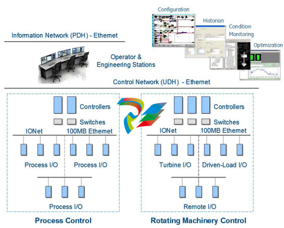
SYSTEM OVERVIEW
A single-board controller is the heart of the system. The controller includes
the main processor and redundant Ethernet drivers to communicate with
networked I/O, and additional Ethernet drivers for the control network. A
real-time, multi-tasking operating system is used for the main processor
and I/O modules. Control software is provided in a configurable control
block language and stored in non-volatile memory. It is similar to IEEE® 854
32-bit floating-point format, and Sequential Function Charts (SFC) are also
available for complex sequencing.
The I/O network (IONet) is a dedicated, full-duplex, point-to-point
protocol. It provides a deterministic, high-speed 100 MB communications
network that is suitable for local or distributed I/O devices, and provides
communication between the main controllers(s) and networked I/O
modules. Online controllers continuously read input data directly
from the IONet, which is available in single, dual, and triple redundant
configurations. Both copper and fiber interfaces are supported.
The Mark VIe I/O modules consist of three basic parts: the terminal board,
the terminal block, and an I/O pack. Barrier or box-type terminal blocks are
mounted on a terminal board, which mounts on a DIN rail or base in the
control cabinet. The I/O pack contains two Ethernet ports, a power supply,
a local processor, and a data acquisition board. I/O capability grows as I/O
packs are added to the control system, enabling use in a simplex, dual, or
triple redundant configuration. Some process sub-systems require even
more throughput; therefore, the local processors in each I/O pack run
algorithms at higher rates as required for the application.
REDUNDANCY
Every application has different requirements for redundancy depending on
the criticality of the process. The Mark VIe control system provides a wide
range of redundancy options for local and remote distribution.
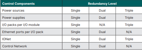
Dual redundant systems transmit inputs from single or redundant input
packs on dual IONets to dual Mark VIe controllers. Controllers then run
application software and transmit outputs to output packs. Three output
I/O packs may be provided to vote output signals for mission-critical field
devices. Dual redundant systems may be configured for single, dual, and
triple redundant sensors.
Triple redundant systems protect against soft or partial device failures. A
failed component is outvoted with a 2-out-of-3 logical selection (vote) or
a median value selection. Control software in all three Mark VIe controllers
runs on the voted value of the signal while diagnostics identify the failed
device. These sophisticated diagnostics reduce the mean-time-to-repair
(MTTR) while the online repair capability increases the mean-timebetween-forced-outages (MTBFO). Field sensors for these systems may
be single, dual, or triple.
I/O INTERFACE
One or multiple I/O packs are mounted on each module to digitize the
sensor signal, run algorithms, and communicate with a separate controller
containing the main processor. I/O packs have a local processor board
that runs a real-time operating system and a data acquisition board that
is unique to the specific I/O application. Local processors run algorithms
at faster speeds than the overall control system, such as the regulation of
servo valves performed within a servo module.
Each I/O processor has a local temperature sensor accurate to ±2°C (±3.6
°F). Detection of an excessive temperature generates a diagnostic alarm
and the logic is available in the database (signal space) to facilitate control
action or unique process alarm messages. The temperature is continuously
available in the database. I/O module features include:
• Dual 100 MB Ethernet ports
• 100 MB full-duplex ports
• Online repair per I/O pack
• Automatic reconfiguration
• Accuracy is specified over full operating temperature
• Internal temperature sensor
• LEDs:
- Power status and attention
- Ethernet link-connected and
communication-active
- Application-specific
• 28 V dc power
• Internal solid-state circuit breaker and soft start
A power supply provides a regulated 28 V dc power feed to each I/O pack.
The negative side of the 28 V dc is grounded through the I/O pack metal
enclosure and its mounting base. The positive side has solid-state circuit
protection built into the I/O pack with a nominal 2 A trip point. Online repair
is possible by removing the 28 V dc connector, replacing the I/O pack, and
re-inserting the power connector. I/O packs are automatically reconfigured
if the Auto-Reconfiguration feature is enabled.
TERMINAL BLOCKS
Signal flow begins with a sensor connected to a terminal block on an I/O
module. The terminal board mounts to the cabinet and is available in two
basic types: T-type and S-type modules.
T-type modules typically fan the inputs to three separate I/O packs.
They contain two removable 24-point, barrier-type terminal blocks. Each
point can accept two 3.0 mm2 (#12,AWG) wires with 300 V insulation per
point and spade or ring-type lugs. Captive clamps are also provided for
terminating bare wires. Screw spacing is 9.53 mm (0.375 in) minimum,
center-to-center. T-type modules are normally surface mounted, but may
also be DIN-rail mounted.
A shield strip is provided next to each block, which is actually the left-hand
side of the metal base where the module is mounted. Wide and narrow
modules are arranged in vertical columns of high and low-level wiring that
can be accessed from top and/or bottom cable entrances. An example of a
wide module is a module containing magnetic relays with fused circuits for
solenoid drivers.
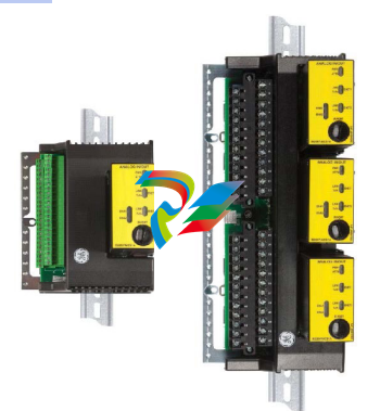
Box-type and Barrier-type Terminal Blocks in Simplex and Triple Redundant Configuration
S-type modules provide a single set of screws for each I/O point and allows
a single I/O pack to condition and digitize the signal. This board is used
for simplex, dual, and dedicated triple modular redundant (TMR) inputs by
using one, two, or three boards. They are half the size of T-type modules
and are DIN-rail or surface mounted. Two versions of the S-type modules
are available: fixed terminal blocks and removable terminal blocks.
Fixed box-type terminal blocks accept one 3.0 mm2 (#12 AWG) wire or two
2.0 mm2 (#14 AWG) wires with 300 V insulation per point. Screw spacing is
5.08 mm (0.2 in) minimum, center-to-center. Removable box terminals may
be replaced with spring-cage-clamp, insulation displacement, or crimpand-stab terminals. A shield strip is provided on each terminal block and is
tied to functional ground.
TEMPERATURE RATINGS
Mark VIe electronics are packaged in different locations world-wide and
customized for a variety of protection classifications with and without
ventilation and cooling. Controllers, I/O modules, power supplies, etc. are
rated for -30 to 65°C (-22 to 149°F) at the electronics. To compliment the
Mark VIe Control’s native I/O modules, a variety of fieldbus solutions are
available with master communication gateways on the I/O network. These
modules have slightly reduced operating temperature ratings:
• PROFIBUS® Master Gateway: -20 to 55°C (-4 to 131°F)
• CANopen® Master Gateway: -20 to 55°C (-4 to 131°F)
• FOUNDATION Fieldbus™ Linking Device: 0 to 55°C (32 to 131°F)
Modules with reduced operating temperatures should be mounted lower
in the cabinet to avoid the natural temperature gradient from the bottom
to the top of the enclosure. Control room equipment such as operator
stations has an operating temperature range of 20 to 30°C (68 to 86°F).
For shipping and storage, the controllers, I/O modules, power supplies, etc.
are rated -40 to 85°C (-40 to 185°F), and control room equipment is rated
0 to 30°C (32 to 86°F).
I/O MODULES
I/O modules can be categorized as generic and application-specific.
As an example, discrete inputs (contact inputs) are used in virtually all
applications and differ primarily in their voltage rating. Other considerations
in selecting a module are its redundancy, isolation (group or point), terminal
block type, availability for safety applications (IEC 61508), and approval for
hazardous locations.
A typical application-specific module is a servo module that is used for
fast closed-loop control of a turbine’s servo valve actuator or a complete
emergency over-speed trip system for a turbine. These unique modules
will not be described in the following tables. However, some applicationspecific modules such as a vibration module is commonly applied in
monitoring radial and axial shaft displacement of rotating machinery in
plant distributed control systems and will be described in a separate table.
Analog Input (AI) and Analog Output (AO) Modules
• V/I designates a voltage / current input
• TC designates thermocouples
• RTD designates resistance temperature device
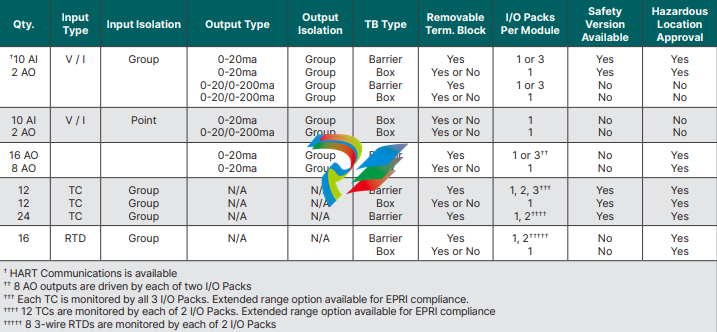
Analog I/O modules typically contain 10 analog inputs and 2 analog outputs. 8 inputs can be configured for
1-5Vdc, ±5Vdc, ±10Vdc, or 0-20ma with jumpers on the module, and the remaining 2 inputs can be configured for
0-20ma or +/-1ma with 250 Ω / 5,000 Ω burden resistors respectively. For applications with a high concentration
of analog outputs, dedicated output modules are available for 0-20ma and others for 0-20ma / 0-200ma selection
for valve actuators (800 Ω / 50 Ω output loads respectively). Transducers can be externally powered (differential
inputs) or internally powered from the I/O module with +24Vdc current limited per point. I/O modules are available
with point isolation for externally powered transducers.
In general, RTDs are useful for precision temperature measurements below 800°C, and thermocouples are cost
effective devices for monitoring a wider temperature range. RTD modules provide a 10 ma multiplexed excitation
current to each RTD, which can be grounded or ungrounded. They support 100 and 200 Ω platinum, 10 Ω copper,
and 120 Ω nickel 3-wire RTDs with software linearization per point. The linearization includes scaling for specific
RTD standards such as a MINCO-CA or CU10 10 Ω copper RTDs. RTDs can be located up to 300 meters (984
feet) from the I/O module with a maximum two-way cable resistance of 15 Ω.
-
 HIRSCHMANN MSM20-M2M2M2M2SY9HH9E Ethernet media modul
 -
 HIRSCHMANN SPIDER-PL-20-05T1999999TWVHHHH Industrial Ethernet Rail Switch
 -
 Hirschmann SPIDER-PL-20-07T1M2M299TWVHHHH Industrial ETHERNET Rail Switch
 -
.png) Hirschmann (Belden) RS20-1600M2M2SDAEHC09.1.00 DIN-rail managed industrial Fast Ethernet switch
Hirschmann (Belden) RS20-1600M2M2SDAEHC09.1.00 DIN-rail managed industrial Fast Ethernet switch -
 Hirschmann (Belden) RS30-1602O6O6TDAPHC09.1.00 DIN-rail managed industrial Ethernet switch
 -
 Hirschmann (Belden) RS30-2402O6T1SDAPHH09.0.13 DIN-rail industrial Ethernet switch
 -
Hirschmann (Belden) SPIDER-PL-20-04T1S29999TY9HHHH Ethernet DIN-rail switch
-
 HIRSCHMANN RS20-1600T1T1SDAUHX Switch
 -
 HIRSCHMANN BRS42-0012OOOO-SPCZ99HHSES industrial switch
 -
 Hirschmann RS20-0800S2S2TDHPHH09.0.14 Fast Ethernet DIN rail switch.
 -
 HIRSCHMANN MM20-Z6Z6M2M2SAHH Hybrid Fast Ethernet Media Module
 -
 HIRSCHMANN MM20-Z6Z6T1T1SAHH hot-swappable hybrid Fast Ethernet Media Module
 -
 HIRSCHMANN MM20-P9P9T1T1SAHH Hybrid Fast Ethernet Media Module
 -
 HIRSCHMANN MM20-M4T1T1T1SAHH Hybrid Fast Ethernet Media Module
 -
 HIRSCHMANN MM20-M4M4T1T1SAHH Hybrid Fast Ethernet Media Module
 -
 HIRSCHMANN MM20-M2M2M2M2SZHH Ethernet media module
 -
HIRSCHMANN MM20-M2M2M2M2SAHH Ethernet media module
-
 HIRSCHMANN MM20-T1T1T1T1EBH 4-port Fast Ethernet Copper Cable Media Module
 -
HIRSCHMANN MM20-T1T1T1T1SAHH 4-port Fast Ethernet Copper Cable Media Module
-
HIRSCHMANN MM20-T1T1T1T1SAHH 4-port Fast Ethernet Copper Cable Media Module
-
 HIRSCHMANN MM20-Z6Z6EBH Hot-swappable fast Ethernet media module
 -
 HIRSCHMANN MM20-Z6Z6SAHH Ethernet media module
 -
HIRSCHMANN MM20-Z6Z6Z6Z6EBH Industrial Media Module
-
 MSM40-T1T1T1TZ9HH9E99.9.99 HIRSCHMANN Switch
 -
 HIRSCHMANN MS20-0800SAAEHC / MS20-0800SAAEHC0 8-port modular Layer 2 management Ethernet switch
 -
 Hirschmann RSPM20-4T14T1SZ9HHS9 Switch RSPM20-4T14T1SZ9HHS9
 -
 HIRSCHMANN RS20-1600M2M2SDAEHH09.1. RS20/30/40 Managed Switch configurator
 -
HIRSCHMANN RS20-1600M2M2SDAEHX09.0.00 Ethernet switch
-
 HIRSCHMANN BELDEN SPIDER-PL-20-07T1M2M299TY9HHHH / SPIDERPL2007T1M2M299TY9HHHH
 -
HIRSCHMANN MM3-1FXS2/3TX1 Switching Board Module
-
 HIRSCHMANN RSPE30-24044O7T99-ECCP999HHSE2A08.1.00 Industrial-grade fanless management-type Ethernet switch
 -
 HIRSCHMANN RS30-1602OOZZSDAEHC09.1.00 DIN-rail-mounted managed Layer 2 Ethernet switch
 -
 HIRSCHMANN MACH104-20TX-F Managed 24-port Full Gigabit 19" Switch
 -
 HIRSCHMANN Switch RS20-0800M4M4SDAE
 -
Hirschmann RS30-1602O6O6SDAEHH09.1. Management-type Ethernet switch
-
 Hirschmann RS30-1602OOZZSDAEHC09.0.10 Open rack-style Ethernet switch
 -
 HIRSCHMANN RSPE30-24044O7T99-SCCV999HHSI2SXX.X.XX High-Availability Seamless Redundancy
 -
HIRSCHMANN RSPE30-24044O7T99-SCCZ999HHSE2A DIN-rail Ethernet switch
-
HIRSCHMANN MM2-4TX1-EEC switch
-
HIRSCHMANN MSM40-T1T1T1T1TZ9HH9E99.9.99 Module
-
 HIRSCHMANN RS20 Rail Switch RS20-0400S4T1SDAEHC07.1.01
 -
 HIRSCHMANN M4-FAST8-SFP Fast Ethernet media module
 -
 HIRSCHMANN RS20-0400M2T1SDAP Managed Fast-Ethernet-Switch
 -
 HIRSCHMANN BELDEN SPIDER II 8TX/1FX EEC Industrial Ethernet Rail Switch
 -
HIRSCHMANN MM3-2FXS2/2TX1
-
 HIRSCHMANN RS2-4TX/1FX EEC Industrial Ethernet Rail Switch
 -
 RS30-0802O6O6SDAEHC09.0.10 HIRSCHMANN Switch
 -
 HIRSCHMANN m4-8TP-RJ45 Ethernet Media Module
 -
 HIRSCHMANN MSP30-24040SCZ9URHHE3A switch
 -
 Hirschmann rack MS30-1602SAAPHC
 -
 HIRSCHMANN RS2-FX/FX Industrial Switch Module
 -
Rs1txfx - Hirschmann - Rs1-Tx/Fx Rail Switch
-
RS20-0800S2S2SDAEHC09.1.00 HIRSCHMANN Commutator
-
 Hirschmann EAGLE20 TX/TX Industrial Security Router
 -
 Hirschmann SPIDER-SL-20-04T1S29999SY9HHHH Industrial Switch
 -
 HIRSCHMANN MAR1040-4C4C4C4C9999SMMHRHHXX.X. Gigabit Ethernet Switch configurator
 -
 Hirschmann MAR1040 Industrial Switch
 -
 HIRSCHMANN BELDEN RS30-1602O6O6SDAE
 -
Hirschmann RS20-1600M2M2SDAUHC Ethernet DIN rail switch
-
 HIRSCHMANN OCTOPUS 24M industrial switch
 -
 HIRSCHMANN RS20-1600T1T1SDAE Management-type Ethernet switch
 -
 HIRSCHMANN RS20-1600T1T1SDAUHH industrial switch
 -
HIRSCHMANN RS20-0800M2M2SDAPHC09.0.04 switch
-
 Hirschmann MR 8-03 24V DC Industrial Modular Bridge/Router
 -
 HIRSCHMANN RS20-0400M2T1SDAPHC08.0.01 Managed Switch
 -
 MACH1130 Hirschmann Industrial Switch
 -
 HIRSCHMANN 943824-002 SPIDER 5TX Industrial Ethernet Switch
 -
 HIRSCHMANN RS30-0802O6O6SDAEHC09.1.00 Managed Industrial Switch
 -
 HIRSCHMANN RS20-0400M2M2TDAEHC04.0.01 Industrial Switch
 -
 HIRSCHMANN BRS20-0600Z6Z6-STCZ99HHSES Industrial Switch
 -
 HIRSCHMANN MACH104-20TX-FR-L3P Industrial Ethernet Switch
 -
 HIRSCHMANN RS40-0009CCCCEDBPHH06.0.01 Industrial Switch
 -
 HIRSCHMANN RS2-3TX/2FX EEC Industrial Ethernet Switch
 -
 Hirschmann MACH 1020/1030 Fast/Gigabit Rack Mount Switches
 -
HIRSCHMANN RS20-0800M2M2SDAPHC09.0.14 Industrial Switch
-
 HIRSCHMANN RS20-1600T1T1SDAEHC09.0.04 Industrial Switch
 -
 HIRSCHMANN RSB20-0800T1T1EAABHH Industrial Switch
 -
 HIRSCHMANN MACH4002-48+4G-L3E Industrial Backbone Switch
 -
 HIRSCHMANN RS20-0400S2T1SDAE Industrial Managed Switch
 -
HIRSCHMANN RS20-0800S2T1SDAUHC Industrial Switch
-
 HIRSCHMANN RS20-2400S4S4SDAEHC09.0.14 industrial switch
 -
 HIRSCHMANN OS20-001200T5T5T5- TBBZ999HHNE3S 08.1.00 industrial switch
 -
HIRSCHMANN OS20-001200T5T5T5- TBBZ999HHNE3S 08.1.00 industrial switch
-
 HIRSCHMANN RS40-0009CCCCSDAEHH09.0.14 switch
 -
 Hirschmann RS20-1600T1T1SDAUHC Management-type Ethernet Switch
 -
 Hirschmann M1-8SFP Switche
 -
Hirschmann Industrial Ethernet Ruggedized Switch MACH1000 Family
-
 Basler Electric, Solid State Protective Relay, BE1-60
 -
BASLER ELECTRIC SR4A-2B15B3A Static Voltage Regulator
-
.png) BASLER ELECTRIC EXCITER DIODE MONITOR EDM-200
BASLER ELECTRIC EXCITER DIODE MONITOR EDM-200 -
.png) BASLER ELECTRIC DECS125-15-B2C5 DIGITAL EXCITATION CONTROL SYSTEM V 2.0.9
BASLER ELECTRIC DECS125-15-B2C5 DIGITAL EXCITATION CONTROL SYSTEM V 2.0.9 -
 BASLER ELECTRIC BE1-851 OVERCURRENT PROTECTION RELAY MECHANISM
 -
 Basler Electric BE1-51A / BE151A
 -
 Basler Electric BE1-40Q Loss of Excitation Relay
 -
 Basler Electric BE1-87G Variable Percentage Differential Relay
 -
 Basler Electric BE1-11 Protection System I5A3M2P2N0EA00
 -
 BASLER ELECTRIC DECS-200-1C Digital Excitation Control System
 -
 Basler Electric / Kohler BE1-11g Generator Protection Relay G5A3M2J2N0E000
 -
BASLER ELECTRIC DECS125-15 DIGITAL EXCITATION CONTROL SYSTEM
-
 BASLER ELECTRIC BE1-951 OverCurrent Protecton System
 -
Basler Electric DECS-200-1L Digital Excitation Control System
-
 Basler Electric DGC-2020HD-5NS1DNSBA Digital Genset Controller -
 -
 BASLER ELECTRIC BE1-81T1EE1WA0N1F / BE181T1EE1WA0N1F
 -
 BASLER ELECTRIC BE1-25M1EA6PN5R1F / BE125M1EA6PN5R1F
 -
 BASLER ELECTRIC DECS-250-LN1SN1N DIGITAL EXCITATION CONTROL SYSTEM
 -
Basler Electric DECS-250-CN2CN 1N Digital Excitation Control System Unit
-
 BASLER ELECTRIC DECS-300-C0N0 DIGITAL EXCITATION CONTROL SYSTEM
 -
 BASLER ELECTRIC BE1-87T-A1E-A1J-D0S1F / BE187TA1EA1JD0S1F
 -
BASLER ELECTRIC BE1-11-G6D1M0J2P0E000 Protection System
-
 BASLER ELECTRIC BE1-GPS100-E4N1H1N GENERATOR PROTECTION SYSTEM
 -
 Jaquet Relay card (Auxiliary module) FTV 3090 377Z-03985
 -
 Jaquet Trip Chain Control card FTBU 3034 377Z-05030
 -
 Jaquet with input card -E04 FTFU 3024 -E04 377Z-05855
 -
 Jaquet with input card -E03 FTFU 3024- E03 377Z-03983
 -
 Jaquet FTFU 3024- E02 377Z-03982 with input card -E02
 -
 Jaquet FTFU 3024-E01 377Z-03981 with input card -E01
 -
 Hirschmann RS20-2400T1T1SDAE Industrial Managed Ethernet Switch
 -
 Hirschmann BELDEN EAGLE30-04022O6TT999SCCV9HSE3F
 -
 Hirschmann MM3-2FXS2/2TX MICE Media Module
 -
 Hirschmann RS20-1600M2M2SDAPHC08.0.05 Industrial Managed Switch
 -
 Hirschmann OZD Profi 12M G12-1300 PRO Fieldbus Repeater
 -
Hirschmann SPIDER 4TX/1FX-ST EEC Industrial Ethernet Switch
-
 Hirschmann MM2-2FXM3/2TX1 MICE Media Module
 -
 Hirschmann RS20-2400M2M2SDAPHC09.0.14 Industrial Switch
 -
 Hirschmann RS20-0400M2M2SDAEHC07.1.05 OpenRail Switch
 -
 Hirschmann OZD Profi 12M G12-EEC Fieldbus Repeater
 -
HIRSCHMANN MDA422-1/2-3.5c-23/46 sensor
-
Hirschmann RS30-2402T1T1SDAUHC Managed Industrial Switch


