
GEHydran* M2 Transformer Gas Monitoring System Installation Guide
Safety Warnings In Six Languages
[EN] (in English) WARNINGS:
• All procedures in this manual must be strictly adhered to.
• Any deviation from these could cause irreversible damage to the transformer
being monitored and/or the Hydran M2, and could lead to property damage,
personal injury and/or death.
• Installation and maintenance of the Hydran M2 must be carried out by qualified
personnel only. Please advise station operator prior to maintenance. Working
inside the Hydran M2 may trigger unwanted alarms due to parameter changes,
power shutdown, system rebooting or electrostatic discharge.
• For a maximum distance of 15 m (50 ft) from the power source, use a 2.08 mm2
(14-AWG) cable and an overcurrent protection.
[FR] (in French) ATTENTION:
• Toutes les procédures dans ce manuel doivent être observées rigoureusement.
• Tout écart par rapport à celles-ci pourrait causer des dommages irréversibles au
transformateur surveillé et/ou au Hydran M2, et pourrait entraîner des dommages
à la propriété, des blessures corporelles et/ou la mort.
• L'installation et l'entretien du Hydran M2 doivent être effectués par du personnel
qualifié seulement. Veuillez aviser l'opérateur du poste avant l'entretien. Travailler
à l'intérieur du Hydran M2 peut déclencher des alarmes non voulues en raison de
changements à des paramètres, d'arrêt de l'alimentation, de remise en marche du
système ou de décharge électrostatique.
• Pour une distance maximale de 15 m (50 pi) de la source d'alimentation, utiliser un
câble de 2,08 mm2 (14-AWG) et une protection contre les surintensités.
[ES] (in Spanish) ADVERTENCIA:
• Se debe c
Cualquier desviación al respecto puede causar daños irreparables al
transformador que está bajo monitoreo y/o al Hydran M2, asimismo puede ser
causa de daños materiales, lesiones corporales y/o muerte.
• La instalación y mantenimiento del equipo Hydran M2 se reserva únicamente al
personal perfectamente cualificado. Aconseje por favor a operador de la estación
antes del mantenimiento. El trabajo dentro del Hydran M2 puede accionar alarmas
indeseadas debido a los cambios del parámetro, parada de la energía, sistema
que reanuda o descarga electrostática.
• Para una distancia máxima de 15 m (50 pies) de la fuente de alimentación, utilice
un cable de 2,08 mm2 (14-AWG) y una protección contra las sobrecargas de
corriente.
[DE] (in German) WARNUNG:
• Alle Abläufe in diesem Handbuch müssen strengstens befolgt werden.
• Jede Abweichung davon könnte dem zu überwachenden Transformator und/oder
dem Hydran M2 unwiderrufliche Schäden zufügen, und könnte zu Sachschaden,
Personenverletzung und/oder Tod führen.
• Installation und Wartung des Hydran M2 dürfen daher nur von qualifiziertem
Personal durchgeführt werden. Verständigen Sie bitte den Bediener der
Schaltanlage vor der Wartung. Das Arbeiten innerhalb des Hydran M2 kann
aufgrund von Parameteränderungen, Spannungsabschaltung, Neubooten des
Systems oder elektrostatischer Entladung unerwartete Alarme auslösen.
• Für eine maximale Entfernung von 15 m von der Spannungsquelle, verwenden
Sie ein 2,08 mm2 Kabel (14 AWG) und ein Überstromschutz.
[IT] (in Italian) ATTENZIONE:
• Tutte le procedure del presente manuale dovranno essere eseguite in totale
conformità.
• Qualsiasi deviazione dallo stesso manuale potrebbe causare danni irreversibili al
trasformatore sotto monitoraggio e/o all’ Hydran M2, e potrebbe causare danni
alla proprietà, lesioni personali e/o alla morte.
• L’installazione e la manutenzione del Hydran M2 devono essere eseguite solo ed
esclusivamente da personale qualificato. Avissare l’operatore della stazione prima
di manutenzione. Funzionando all’interno del Hydran M2 può fare scattare degli
alarmi indesiderabili e cambiamenti dei parametri, arresto dell’alimentazione, un
“reboot” del sistema o scarico elettrostatico.
• A una distanza massima di 15 m dalla fonte di energia usare un cavo 2.08 mm2
(14-AWG) e una protezione di sovracorrente.
[SV] (in Swedish) VARNING:
• Alla procedurer i manualen måste följas noggrant.
• Varje avvikelse från dessa procedurer kan orsaka oåterkalleliga skador på den
övervakade transformatorn och/eller på Hydran M2 samt leda till
egendomsförlust, personskada och/eller livsfara.
• Installation och underhåll av Hydran M2 måste utföras av behörig personal. Råd
var god posterar operatören före underhåll. Funktionsduglig insida Hydran M2 kan
starta oönskade parameterändringar för larm tack vare, driver avstängning,
systemomstart eller elektrostatisk urladdning.
• För ett maximalt avstånd på 15 m från kraftuttaget, använd 2,08 mm2 kabel (14-
AWG) och ett överströmsskydd.
Safety Symbols Description
Description of safety symbols used on the Hydran M2 device:
Refer to the Instruction Manual to prevent injury or damage
to equipment.
Hazardous voltages may be present.
Protective earth connection.
Description of safety messages used in this Instruction Manual:
A procedure, practice, or condition that could cause equipment
damage or permanent loss of data, if not adhered to.
A procedure, practice, or condition that could cause bodily
injury or death, if not adhered to.
Preface
This manual provides an overview of the installation for the Hydran M2. For
complete explanations on the installation process, see Chapter 4 in the Hydran M2
Instruction Manual.
The information in this manual may be used by:
− An installer
− An electrician
• All procedures in this manual must be strictly adhered to.
Any deviation from these may cause irreversible damage to
the transformer being monitored and/or the Hydran M2,
and may lead to property damage, personal injury and/or
death.
• Installation and maintenance of the Hydran M2 must be
carried out by qualified personnel only.
Any visible signs of damage to the shipping packages should be reported to GE
Energy immediately.
Please keep all documentation (model number, manuals, etc.) for reference and
warranty purposes.
A Table of Contents and a List of Figures are present at the beginning of the
manual.
The Hydran M2 Installation Guide (this manual), the Hydran M2 Instruction Manual
and the Hydran M2 Host Software Manual are located in PDF format in the
English/Manuals folder of the Hydran M2 installation CD. Hard copies of each
manual can be purchased from GE Energy
Standard GE Energy Warranty
The products covered by this manual and manufactured by GE Energy
(“Products”) are warranted to be free from defects in material, workmanship and title
at the time of delivery. Any components of a Product or other products
manufactured by persons other than GE Energy carry only the warranty provided by
the manufacturers thereof and GE Energy gives no warranty on behalf of the
manufacturers of such products.
GE Energy warrants the Products until one (1) year from first use or eighteen
months (18) months from delivery, whichever occurs first, except that software is
warranted for ninety (90) days from delivery.
GE Energy represents and warrants that any software and firmware covered by
this manual is free from functional deficiencies. If any functional deficiencies are
discovered and are reported to GE Energy within the Warranty Period, GE Energy
agrees to use due diligence to correct such deficiencies within 30 days after receipt
of such notification. Upon receiving such notice, GE Energy may lend telephone
support or patches. If the reported deficiencies cannot be eliminated within 30 days,
the Buyer may request, and GE Energy shall then furnish, monthly status reports to
the Buyer regarding the progress of GE Energy’s efforts to correct such functional
deficiencies.
If Products covered by this manual do not meet the above warranties during the
applicable Warranty Period, the Buyer shall promptly notify GE Energy in writing but
not later than 30 days and make the Products available promptly for correction. GE
Energy shall thereupon correct any defect by, at its option, repairing the defective
Products or making available necessary replacement parts.
Any failure which is the basis for a warranty claim shall not be cause for
extension of the duration of the applicable Warranty Period. GE Energy shall not be
responsible for removal or replacement of systems, structures or other parts of the
Buyer’s facility. If a defect in Products or part thereof cannot be corrected by GE
Energy’s reasonable efforts, the parties shall negotiate an equitable adjustment in
price with respect to such Products or part thereof. All decontamination work
necessary for the correction of defects shall be performed by the Buyer at the
Buyer’s expense. The condition of any tests shall be mutually agreed upon and GE
Energy shall be notified of and may be represented at all tests that may be made.
GE Energy does not warrant Products or any repaired or replacement parts
against normal wear and tear, including that due to environment or operation,
including excessive operation at peak capability, frequent starting, type of fuel,
detrimental air inlet conditions, or erosion, corrosion or material deposits from fluids,
or which have been involved in an accident. The warranties and remedies set forth
herein are further conditioned upon:
• Proper storage, installation, operation and maintenance of the Buyer’s
equipment and conformance with the instruction manuals (including revisions
thereto) provided by GE Energy and/or its subcontractors, as applicable
• Repair or modification pursuant to GE Energy’s instructions or approval
The Buyer shall keep proper records of operation and maintenance during the
applicable Warranty Period. These records shall be kept in the form of log sheets and
copies shall be submitted to GE Energy upon its request in connection with a
warranty claim by the Buyer. GE Energy does not warrant any products or services of
others designated by the Buyer where such products or services are not normally
supplied by GE Energy.
The preceding paragraphs set forth the exclusive remedies for all claims based
on failure of or defect in Products covered by this manual, whether the failure or
defect arises before or during the applicable Warranty Period and whether a claim,
however instituted, is based on contract, indemnity, warranty, tort (including
negligence) or civil liability, strict liability or otherwise. The foregoing warranties are
exclusive and are in lieu of all other warranties and guarantees whether written, oral,
implied or statutory. NO IMPLIED STATUTORY WARRANTY OF MERCHANTABILITY OR
FITNESS FOR A PARTICULAR PURPOSE SHALL APPLY.
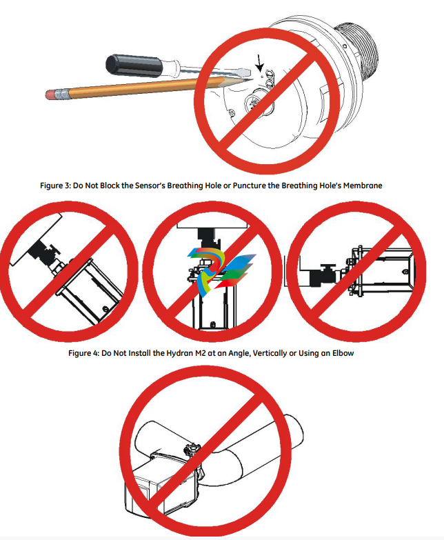
GENERAL WARNINGS
• Mishandling of the Hydran M2 sensor (such as a
perforation or scratch on the membrane or subjecting
the sensor to paint or solvent) voids the warranty.
• It is recommended to read all warnings and
considerations given in Chapter 1 of the Hydran M2
Instruction Manual before proceeding with the
installation.

Figure 2: Do Not Touch the Sensor’s Membrane with a Finger or an Object
Hydran* M2 Installation Guide
Hydran* M2 Installation Guide
16375 v9.0 Oct 12
For a typical transformer, the four most common locations to install the Hydran
M2 are shown in Figure 10. For details, refer to Table 1 overleaf.
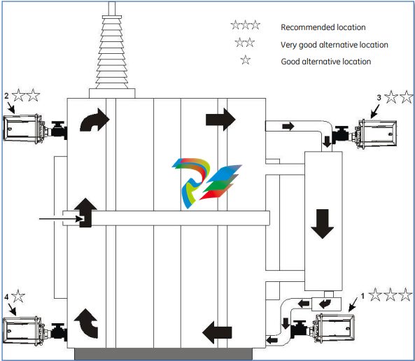
If these typical locations cannot be used, contact the GE
Energy Customer Service for help to determine an
acceptable alternative location.
• ELECTRICAL SHOCK HAZARD! Turn off the electric power at
the fuse box or service panel before making any electrical
connections, and ensure a proper ground connection is
made before connecting line voltage. Failure to do so can
result in property damage, personal injury and/or death.
-
 HIRSCHMANN MSM20-M2M2M2M2SY9HH9E Ethernet media modul
 -
 HIRSCHMANN SPIDER-PL-20-05T1999999TWVHHHH Industrial Ethernet Rail Switch
 -
 Hirschmann SPIDER-PL-20-07T1M2M299TWVHHHH Industrial ETHERNET Rail Switch
 -
.png) Hirschmann (Belden) RS20-1600M2M2SDAEHC09.1.00 DIN-rail managed industrial Fast Ethernet switch
Hirschmann (Belden) RS20-1600M2M2SDAEHC09.1.00 DIN-rail managed industrial Fast Ethernet switch -
 Hirschmann (Belden) RS30-1602O6O6TDAPHC09.1.00 DIN-rail managed industrial Ethernet switch
 -
 Hirschmann (Belden) RS30-2402O6T1SDAPHH09.0.13 DIN-rail industrial Ethernet switch
 -
Hirschmann (Belden) SPIDER-PL-20-04T1S29999TY9HHHH Ethernet DIN-rail switch
-
 HIRSCHMANN RS20-1600T1T1SDAUHX Switch
 -
 HIRSCHMANN BRS42-0012OOOO-SPCZ99HHSES industrial switch
 -
 Hirschmann RS20-0800S2S2TDHPHH09.0.14 Fast Ethernet DIN rail switch.
 -
 HIRSCHMANN MM20-Z6Z6M2M2SAHH Hybrid Fast Ethernet Media Module
 -
 HIRSCHMANN MM20-Z6Z6T1T1SAHH hot-swappable hybrid Fast Ethernet Media Module
 -
 HIRSCHMANN MM20-P9P9T1T1SAHH Hybrid Fast Ethernet Media Module
 -
 HIRSCHMANN MM20-M4T1T1T1SAHH Hybrid Fast Ethernet Media Module
 -
 HIRSCHMANN MM20-M4M4T1T1SAHH Hybrid Fast Ethernet Media Module
 -
 HIRSCHMANN MM20-M2M2M2M2SZHH Ethernet media module
 -
HIRSCHMANN MM20-M2M2M2M2SAHH Ethernet media module
-
 HIRSCHMANN MM20-T1T1T1T1EBH 4-port Fast Ethernet Copper Cable Media Module
 -
HIRSCHMANN MM20-T1T1T1T1SAHH 4-port Fast Ethernet Copper Cable Media Module
-
HIRSCHMANN MM20-T1T1T1T1SAHH 4-port Fast Ethernet Copper Cable Media Module
-
 HIRSCHMANN MM20-Z6Z6EBH Hot-swappable fast Ethernet media module
 -
 HIRSCHMANN MM20-Z6Z6SAHH Ethernet media module
 -
HIRSCHMANN MM20-Z6Z6Z6Z6EBH Industrial Media Module
-
 MSM40-T1T1T1TZ9HH9E99.9.99 HIRSCHMANN Switch
 -
 HIRSCHMANN MS20-0800SAAEHC / MS20-0800SAAEHC0 8-port modular Layer 2 management Ethernet switch
 -
 Hirschmann RSPM20-4T14T1SZ9HHS9 Switch RSPM20-4T14T1SZ9HHS9
 -
 HIRSCHMANN RS20-1600M2M2SDAEHH09.1. RS20/30/40 Managed Switch configurator
 -
HIRSCHMANN RS20-1600M2M2SDAEHX09.0.00 Ethernet switch
-
 HIRSCHMANN BELDEN SPIDER-PL-20-07T1M2M299TY9HHHH / SPIDERPL2007T1M2M299TY9HHHH
 -
HIRSCHMANN MM3-1FXS2/3TX1 Switching Board Module
-
 HIRSCHMANN RSPE30-24044O7T99-ECCP999HHSE2A08.1.00 Industrial-grade fanless management-type Ethernet switch
 -
 HIRSCHMANN RS30-1602OOZZSDAEHC09.1.00 DIN-rail-mounted managed Layer 2 Ethernet switch
 -
 HIRSCHMANN MACH104-20TX-F Managed 24-port Full Gigabit 19" Switch
 -
 HIRSCHMANN Switch RS20-0800M4M4SDAE
 -
Hirschmann RS30-1602O6O6SDAEHH09.1. Management-type Ethernet switch
-
 Hirschmann RS30-1602OOZZSDAEHC09.0.10 Open rack-style Ethernet switch
 -
 HIRSCHMANN RSPE30-24044O7T99-SCCV999HHSI2SXX.X.XX High-Availability Seamless Redundancy
 -
HIRSCHMANN RSPE30-24044O7T99-SCCZ999HHSE2A DIN-rail Ethernet switch
-
HIRSCHMANN MM2-4TX1-EEC switch
-
HIRSCHMANN MSM40-T1T1T1T1TZ9HH9E99.9.99 Module
-
 HIRSCHMANN RS20 Rail Switch RS20-0400S4T1SDAEHC07.1.01
 -
 HIRSCHMANN M4-FAST8-SFP Fast Ethernet media module
 -
 HIRSCHMANN RS20-0400M2T1SDAP Managed Fast-Ethernet-Switch
 -
 HIRSCHMANN BELDEN SPIDER II 8TX/1FX EEC Industrial Ethernet Rail Switch
 -
HIRSCHMANN MM3-2FXS2/2TX1
-
 HIRSCHMANN RS2-4TX/1FX EEC Industrial Ethernet Rail Switch
 -
 RS30-0802O6O6SDAEHC09.0.10 HIRSCHMANN Switch
 -
 HIRSCHMANN m4-8TP-RJ45 Ethernet Media Module
 -
 HIRSCHMANN MSP30-24040SCZ9URHHE3A switch
 -
 Hirschmann rack MS30-1602SAAPHC
 -
 HIRSCHMANN RS2-FX/FX Industrial Switch Module
 -
Rs1txfx - Hirschmann - Rs1-Tx/Fx Rail Switch
-
RS20-0800S2S2SDAEHC09.1.00 HIRSCHMANN Commutator
-
 Hirschmann EAGLE20 TX/TX Industrial Security Router
 -
 Hirschmann SPIDER-SL-20-04T1S29999SY9HHHH Industrial Switch
 -
 HIRSCHMANN MAR1040-4C4C4C4C9999SMMHRHHXX.X. Gigabit Ethernet Switch configurator
 -
 Hirschmann MAR1040 Industrial Switch
 -
 HIRSCHMANN BELDEN RS30-1602O6O6SDAE
 -
Hirschmann RS20-1600M2M2SDAUHC Ethernet DIN rail switch
-
 HIRSCHMANN OCTOPUS 24M industrial switch
 -
 HIRSCHMANN RS20-1600T1T1SDAE Management-type Ethernet switch
 -
 HIRSCHMANN RS20-1600T1T1SDAUHH industrial switch
 -
HIRSCHMANN RS20-0800M2M2SDAPHC09.0.04 switch
-
 Hirschmann MR 8-03 24V DC Industrial Modular Bridge/Router
 -
 HIRSCHMANN RS20-0400M2T1SDAPHC08.0.01 Managed Switch
 -
 MACH1130 Hirschmann Industrial Switch
 -
 HIRSCHMANN 943824-002 SPIDER 5TX Industrial Ethernet Switch
 -
 HIRSCHMANN RS30-0802O6O6SDAEHC09.1.00 Managed Industrial Switch
 -
 HIRSCHMANN RS20-0400M2M2TDAEHC04.0.01 Industrial Switch
 -
 HIRSCHMANN BRS20-0600Z6Z6-STCZ99HHSES Industrial Switch
 -
 HIRSCHMANN MACH104-20TX-FR-L3P Industrial Ethernet Switch
 -
 HIRSCHMANN RS40-0009CCCCEDBPHH06.0.01 Industrial Switch
 -
 HIRSCHMANN RS2-3TX/2FX EEC Industrial Ethernet Switch
 -
 Hirschmann MACH 1020/1030 Fast/Gigabit Rack Mount Switches
 -
HIRSCHMANN RS20-0800M2M2SDAPHC09.0.14 Industrial Switch
-
 HIRSCHMANN RS20-1600T1T1SDAEHC09.0.04 Industrial Switch
 -
 HIRSCHMANN RSB20-0800T1T1EAABHH Industrial Switch
 -
 HIRSCHMANN MACH4002-48+4G-L3E Industrial Backbone Switch
 -
 HIRSCHMANN RS20-0400S2T1SDAE Industrial Managed Switch
 -
HIRSCHMANN RS20-0800S2T1SDAUHC Industrial Switch
-
 HIRSCHMANN RS20-2400S4S4SDAEHC09.0.14 industrial switch
 -
 HIRSCHMANN OS20-001200T5T5T5- TBBZ999HHNE3S 08.1.00 industrial switch
 -
HIRSCHMANN OS20-001200T5T5T5- TBBZ999HHNE3S 08.1.00 industrial switch
-
 HIRSCHMANN RS40-0009CCCCSDAEHH09.0.14 switch
 -
 Hirschmann RS20-1600T1T1SDAUHC Management-type Ethernet Switch
 -
 Hirschmann M1-8SFP Switche
 -
Hirschmann Industrial Ethernet Ruggedized Switch MACH1000 Family
-
 Basler Electric, Solid State Protective Relay, BE1-60
 -
BASLER ELECTRIC SR4A-2B15B3A Static Voltage Regulator
-
.png) BASLER ELECTRIC EXCITER DIODE MONITOR EDM-200
BASLER ELECTRIC EXCITER DIODE MONITOR EDM-200 -
.png) BASLER ELECTRIC DECS125-15-B2C5 DIGITAL EXCITATION CONTROL SYSTEM V 2.0.9
BASLER ELECTRIC DECS125-15-B2C5 DIGITAL EXCITATION CONTROL SYSTEM V 2.0.9 -
 BASLER ELECTRIC BE1-851 OVERCURRENT PROTECTION RELAY MECHANISM
 -
 Basler Electric BE1-51A / BE151A
 -
 Basler Electric BE1-40Q Loss of Excitation Relay
 -
 Basler Electric BE1-87G Variable Percentage Differential Relay
 -
 Basler Electric BE1-11 Protection System I5A3M2P2N0EA00
 -
 BASLER ELECTRIC DECS-200-1C Digital Excitation Control System
 -
 Basler Electric / Kohler BE1-11g Generator Protection Relay G5A3M2J2N0E000
 -
BASLER ELECTRIC DECS125-15 DIGITAL EXCITATION CONTROL SYSTEM
-
 BASLER ELECTRIC BE1-951 OverCurrent Protecton System
 -
Basler Electric DECS-200-1L Digital Excitation Control System
-
 Basler Electric DGC-2020HD-5NS1DNSBA Digital Genset Controller -
 -
 BASLER ELECTRIC BE1-81T1EE1WA0N1F / BE181T1EE1WA0N1F
 -
 BASLER ELECTRIC BE1-25M1EA6PN5R1F / BE125M1EA6PN5R1F
 -
 BASLER ELECTRIC DECS-250-LN1SN1N DIGITAL EXCITATION CONTROL SYSTEM
 -
Basler Electric DECS-250-CN2CN 1N Digital Excitation Control System Unit
-
 BASLER ELECTRIC DECS-300-C0N0 DIGITAL EXCITATION CONTROL SYSTEM
 -
 BASLER ELECTRIC BE1-87T-A1E-A1J-D0S1F / BE187TA1EA1JD0S1F
 -
BASLER ELECTRIC BE1-11-G6D1M0J2P0E000 Protection System
-
 BASLER ELECTRIC BE1-GPS100-E4N1H1N GENERATOR PROTECTION SYSTEM
 -
 Jaquet Relay card (Auxiliary module) FTV 3090 377Z-03985
 -
 Jaquet Trip Chain Control card FTBU 3034 377Z-05030
 -
 Jaquet with input card -E04 FTFU 3024 -E04 377Z-05855
 -
 Jaquet with input card -E03 FTFU 3024- E03 377Z-03983
 -
 Jaquet FTFU 3024- E02 377Z-03982 with input card -E02
 -
 Jaquet FTFU 3024-E01 377Z-03981 with input card -E01
 -
 Hirschmann RS20-2400T1T1SDAE Industrial Managed Ethernet Switch
 -
 Hirschmann BELDEN EAGLE30-04022O6TT999SCCV9HSE3F
 -
 Hirschmann MM3-2FXS2/2TX MICE Media Module
 -
 Hirschmann RS20-1600M2M2SDAPHC08.0.05 Industrial Managed Switch
 -
 Hirschmann OZD Profi 12M G12-1300 PRO Fieldbus Repeater
 -
Hirschmann SPIDER 4TX/1FX-ST EEC Industrial Ethernet Switch
-
 Hirschmann MM2-2FXM3/2TX1 MICE Media Module
 -
 Hirschmann RS20-2400M2M2SDAPHC09.0.14 Industrial Switch
 -
 Hirschmann RS20-0400M2M2SDAEHC07.1.05 OpenRail Switch
 -
 Hirschmann OZD Profi 12M G12-EEC Fieldbus Repeater
 -
HIRSCHMANN MDA422-1/2-3.5c-23/46 sensor
-
Hirschmann RS30-2402T1T1SDAUHC Managed Industrial Switch


