
WATLOWMLS300 Series User’s Guide
Manual Contents
This manual describes how to install, setup, and operate a
MLS316 or MLS332 controller. Each chapter covers a
different aspect of your control system and may apply to
different users. The following describes each chapter’s
purpose.
• Chapter 1: System Overview. Provides a component list
and summary of features for the MLS300 controllers.
• Chapter 2: Installation. Provides detailed instructions
on installing the MLS300 controller and its peripherals.
• Chapter 3: Using the MLS300. Provides an overview of
operator displays used for system monitoring and job
selection.
• Chapter 4: Setup. Provides detailed descriptions of all
menus and menu options for controller setup.
• Chapter 5: Extruder Options. Explains the additional
features on an MLS300 controller equipped with Extruder
Control Firmware.
• Chapter 6: Enhanced Features. Describes process
variable retransmit, ratio, differential and cascade control
features available with the enhanced features option.
• Chapter 7: Ramp/Soak. Explains how to setup and use
the features of the ramp/soak option.
• Chapter 8: Tuning and Control. Describes available
control algorithms and provides suggestions for
applications.
• Chapter 9: Troubleshooting and Reconfiguring.
Includes troubleshooting, upgrading and reconfiguring
procedures for technical personnel.
• Chapter 10: Linear Scaling Examples. Provides an
example configuring a pressure sensor, a flow sensor, and
an encoder using linear scaling.
• Chapter 11: Specifications. Lists detailed specifications
of the controller and optional components.
Getting Started
The following sections provide information regarding product
features, technical descriptions, safety requirements, and
preparation for operation.
These symbols are used throughout this manual:
DANGER! Indicates potential for serious injury or loss
of human life.
WARNING! Indicates possible damage to property or
equipment.
NOTE! Indicates pertinent information in order to
proceed.
Initial Inspection
Accessories may or may not be shipped in the same container
as the MLS300, depending upon their size. Check the
shipping invoice carefully against the contents received in all
boxes.
Product Features
The MLS300 series controllers provide 16 or 32 fully
independent loops of PID control. When used as a stand-alone
controller, you may operate the MLS300 via the two-line 16-
character display and touch keypad. You can also use it as the
key element in a computer-supervised data acquisition and
control system; the MLS300 can be locally or remotely
controlled via an EIA/RS-232 or EIA/RS-485 serial
communications interface.
The MLS300 features include:
• Direct Connection of Mixed Thermocouple Sensors:
Connect most thermocouples to the controller with no
hardware modifications. Thermocouple inputs feature
reference junction compensation, linearization, process
variable offset calibration to correct for sensor
inaccuracies, detection of broken, shorted or reversed
thermocouples, and a choice of Fahrenheit or Celsius
display.
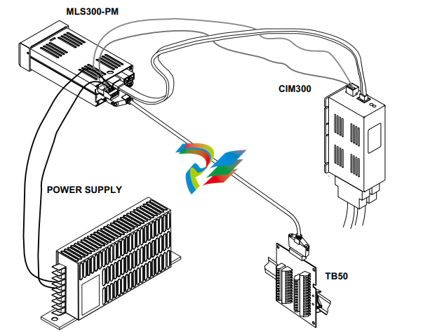
• CIM300 Input Option: The CIM300 input module
provides high density sensor termination with a smaller
installation footprint and faster installation.
• Accepts Resistive Temperature Detectors (RTDs): Use
3-wire, 100 ohm, platinum, DIN-curve sensors with two
choices for range and precision of measurements. (To use
this input, order a MLS316 or MLS332 controller with
scaling resistors.)
• Automatic Scaling for Linear Analog Inputs: The
MLS300 series automatically scales linear inputs used
with other industrial process sensors. Enter two points,
and all input values are automatically scaled in your units.
Scaling resistors must be installed.
• Dual Outputs: The MLS300 series includes both heat
and cool outputs for up to 16 loops. Independent control
parameters are provided for each output.
• Independently Selectable Control and Output Modes:
You can set each control output to ON/OFF, Time
Proportioning, Serial DAC, or Distributed Zero Crossing
mode. Set up to two outputs per loop for ON/OFF, P, PI,
or PID control with reverse or direct action.
• Control Outputs: Set high/low deviation and high/low
process limits to operate digital outputs as on/off control
functions or alarms.
• Flexible Alarm Outputs: Independently set high/low
process alarms and a high/low deviation band alarm for
each loop. Alarms can activate a digital output by
themselves, or they can be grouped with other alarms to
activate an output.
• Global Alarm Output: When any alarm is triggered, the
Global Alarm Output is also triggered, and it stays on until
you acknowledge it.
• CPU Watchdog: The MLS300 series CPU watchdog
timer output notifies you of system failure. You can use it
to hold a relay closed while the controller is running, so
you are notified if the microprocessor shuts down.
• Front Panel or Computer Operation: Set up and run the
controller from the front panel or from a local or remote
computer. WatView software is available to configure
and monitor the MLS300 from a PC.
• Modbus RTU Protocol, EIA/TIA-232 and 485
Communications: Connect to PLCs, operator interface
terminals and third-party software packages using the
widely supported Modbus RTU protocol.
• Multiple Job Storage: Store up to 8 jobs in memory, and
access them locally by entering a single job number or
remotely via digital inputs. Each job is a set of operating
conditions, including set points and alarms.
• Non-Linear Output Curves: Select either of two nonlinear output curves for each control output.
• Autotuning Makes Setup Simple: Use the Autotune
feature to set up your system quickly and easily. The
MLS300 internal expert system table finds the correct
PID parameters for your process.
• Pulse Counter Input: Use the pulse counter input for
precise control of motor or belt speed.
• Low Power Shutdown: The controller shuts down and
turns off all outputs when it detects the input voltage drop
below the minimum safe operating level.
MLS300 Series User’s Guide Chapter 1: System Overview
Doc.# 0600-3070-2000 Watlow Anafaze 5
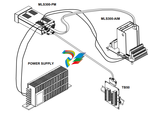
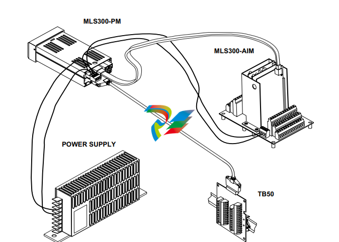
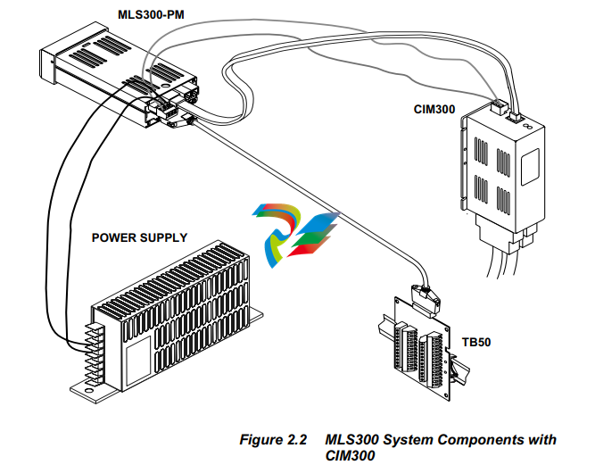
System Diagram
The illustration below shows how the parts of the MLS300 are
connected. When unpacking your system, use the diagram and
parts list below to ensure all parts have been shipped. Please
don't hesitate to call Watlow Anafaze's Customer Service
Department if you have problems with your shipment, or if the
MLS300's components are missing or damaged.
Parts List MLS316/MLS332
You may have received one or more of the following
components. Refer to Figure 1.1 on page 5 and Figure 1.2 on
page 6 for MLS300 configuration information.
• MLS300 Processor Module (PM)
• Controller Mounting Kit
• 16- or 32-Channel MLS300-AIM Module with 4-foot
AIM cable
• 16- or 32-Channel CIM300 Module with 4-foot AIM
cable.
• EIA/RS-232 or EIA/RS-485 Communication Cable
• TB50 with 50-pin SCSI Cable
• Power Supply with Mounting Bracket and Screws
• SDAC (Serial Digital-to-Analog Converter)
• Special Input Resistors (installed in MLS300 AIM)
• User Manual
Technical Description
This section contains a technical description of each
component of your MLS300 Controller.
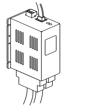
Processor Module
The MLS300 Processor Module (MLS300-PM) is housed in
an eighth-DIN panel mount package. It contains the CPU,
RAM with a built-in battery, EPROM, serial communications,
digital I/O, the screen and touch keypad.
The MLS300-PM has the following features:
• Keypad and 2-line, 16-character display.
• Screw terminals for the power inputs and outputs.
• Input power is 12 to 24 Vdc at 1 amp.
• The +5 Vdc output power supply of the processor module
powers the MLS300-AIM.
• The MLS300-PM interfaces with the MLS300-AIM with
an 8-pin RJ-45 style connector.
• A 50-pin SCSI cable connects the digital inputs and
outputs to the 50-pin terminal block (TB50).
• The MLS300 uses 6-pin, telephone-style connectors for
EIA/RS-232 and EIA/RS-485 external communications.
The program that operates the MLS300 is stored in a socketed,
flash, static-RAM chip, so it is easy to update or change the
firmware. The MLS300 stores its operating parameters in
battery-backed RAM, so if there's a power loss the operating
parameters are unchanged. The battery has a ten year shelf
life, and it is not used when the unit is on.
The microprocessor performs all calculations for input signal
linearization, PID control, alarms, and communications.
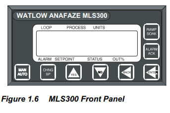
Front Panel Description
The MLS300-PM's display and touch keypad provide an
intelligent way to operate the MLS300. The display has 16
alphanumeric or graphic characters per line. The 8-key
keypad allows you to change the MLS300's operating
parameters, controller functions, and displays.
The MLS300's information-packed displays show process
variables, set points, and output levels for each loop. A bar
graph display, single loop display, scanning display and an
alarm display offer a real-time view of process conditions.
Two access levels allow operator changes and supervisor
changes.
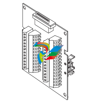
The TB50 is a screw terminal interface for control wiring
which allows you to connect relays, encoders and discrete I/O
devices to the MLS300. The screw terminal blocks accept
wires as large as 18 AWG. A 50-pin SCSI cable connects the
TB50 to the MLS300-PM
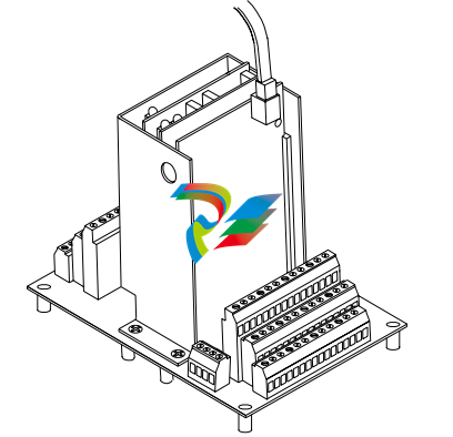
MLS300-AIM and AIM-TB
The MLS300 Analog Input Module (MLS300-AIM), consists
of the AIM-TB (AIM Terminal Board) and the AIM’s plug-in
cards. The MLS300-AIM receives input signals from sensors
and transmits this information to the MLS300-PM through the
AIM cable.
The AIM-TB includes power supply terminals, input signal
wiring screw terminals, input signal conditioning circuits, and
terminal connections for the AIM's plug-in cards. It also
includes a cold junction temperature sensor and room for the
input scaling resistors, if required. (RTDs, inputs greater than
60 mVdc, and mAdc current inputs require input scaling
resistors.) The AIM-TB has three slots for the plug-in AIM
cards.
There are two versions of the MLS300-AIM: the AIM-16 and
AIM-32. The AIM-16 has one multiplexer (MUX) card, and
the AIM-32 has two MUX cards. These cards multiplex the 16
inputs each card receives. Each -10 to 60 mVdc input is
converted to a voltage that is transmitted to the Voltage/
Frequency (V/F) card. (The MUX cards also automatically
calibrate the zero and span of the analog amplifier and
measure the cold junction compensation temperature for
thermocouple inputs.) Both the AIM-16 and AIM-32 have a
V/F card, which converts the input signal voltage to a
frequency. The converted signal is then transmitted via the
AIM cable to the MLS300-PM for processing.
The MLS300 Compact Input Module (CIM300) consists of
two circuit boards that perform analog-to-digital conversion
and data communications to the processor module. The
CIM300 receives input signals from sensors and transmits this
information to the MLS300-PM through the AIM cable.
The CIM300 includes power supply terminals, input signal
connectors, a communications connector and input signal
conditioning circuits. It also includes a cold-junction
temperature sensor and room for the input scaling resistors, if
required. (RTDs, inputs greater than 60 mV dc, and mA dc
current inputs require input scaling resistors.)
There are two versions of the CIM300: the CIM316 and
CIM332. The CIM316 supports 16 inputs through a D-Sub 50
female connector and the CIM332 supports 32 inputs through
2 D-Sub 50 connectors (inputs 1 to 16 female, inputs 17 to 32
male). The user supplies the mating D-Sub 50 connectors. The
CIM300 has one or two multiplexer circuits that multiplex the
16 inputs each card receives. Each -10 to 60 mV dc input is
converted to a voltage that is transmitted to the Voltage/
Frequency (V/F) card. (The mulitplexer circuits also
automatically calibrate the zero and span of the analog
amplifier and measure the cold-junction compensation
temperature for thermocouple (T/C) inputs.) A V/F circuit
converts the input signal voltage to a frequency. The
converted signal is then transmitted via the AIM cable to the
MLS300-PM for processing
MLS300 Cabling
Watlow Anafaze provides cables required to install your
MLS300.
A 50-pin SCSI cable connects the TB50 to the MLS300-PM.
The cable connecting the MLS300-PM to the AIM-TB is an
8-conductor, shielded cable with RJ-45 connectors.
The cables used to connect the MLS300 to EIA/RS-232 or
EIA/RS-485 communications are 6-conductor, shielded cable
with RJ-12 connectors on one end and a DB-9 connector or
bare wires on the other end.
The pin numbering convention used for communications cables varies between suppliers. See Serial Communications, Cable
Connector Pin Outs on page 62.
Safety
Watlow Anafaze has made every effort to ensure the
reliability and safety of this product. In addition, we have
provided recommendations that will allow you to safely
install and maintain this controller.
Ensure that power has been shut off to your
entire process before you begin installation
of the controller.
WARNING! In any application, failures can occur. These
failures can result in full control output (100%
power), or the occurrence of other output failures which can cause damage to the controller, or to the equipment or process
connected to the controller. Therefore, always follow good engineering practices,
electrical codes, and insurance regulations
when installing and operating this equipment.
External Safety Devices
External safety devices should be used to prevent potentially
dangerous and unsafe conditions upon equipment failure.
Always assume that this device can fail with outputs full-on,
or full-off, by the occurrence of an unexpected external
condition.
Always install high or low temperature protection in installations where an over-temperature or under-temperature fault will present
a potential hazard. Failure to install external
protection devices where hazards exist can
result in damage to equipment and property
as well as loss of human life.
Power-Fail Protection
In the occurrence of a sudden loss of power, this controller can
be programmed to reset the control outputs to OFF (this is the
default). Typically, when power is re-started, the controller
restarts to data stored in memory. If you have programmed the
controller to restart with control outputs ON, the memorybased restart might create an unsafe process condition for
some installations. Therefore, you should only set the restart
with outputs ON if you are certain your system will safely
restart. (See Process Power Digital Input on page 98).
When using a computer or host device, you can program the
software to automatically reload desired operating constants
or process values on power-up. Keep in mind that these
convenience features do not eliminate the need for
independent safety devices.
Contact Watlow Anafaze immediately if you have any
questions about system safety or system operation.
This chapter describes how to install the MLS300 series
controller and its peripherals. Installation of the controller
involves the following procedures:
• Determining the best location for the controller
• Mounting the controller, the AIM and the TB50
• Power connection
• Testing the system
• Input wiring
• Output wiring
• Communications wiring (EIA/TIA-232 or EIA/TIA485)
Typical Installation
Figure 2.1 on page 18 illustrates a typical installation of the
MLS300-PM (controller) with the MLS300-AIM (analog
input module), TB50 terminal block, and power supply.
Refer to Figure 2.15 on page 36 for a more detailed view of
the power connections.
Read this entire chapter before beginning the installation
procedure.
Mounting Controller Components
Install the controller in a location free from excessive heat
(more than 50°C), dust and unauthorized handling.
Electromagnetic and radio frequency interference can induce
noise on sensor wiring. Select locations for the MLS300-PM
and MLS300-AIM and CIM300 such that wiring can be
routed clear of sources of interference such as high voltage
wires, power switching devices and motors
! The MLS300 system is for indoor use only. Install it in a controlled environment to reduce
the risk of fire or electric shock.
Recommended Tools
Use these tools to install the MLS300 series controller.
Panel Hole Cutters
Use any of the following tools to cut a hole of the appropriate
size in the panel.
• Jigsaw and metal file, for stainless steel and heavyweight
panel doors.
• Greenlee 1/8 DIN rectangular punch (Greenlee part #
600-68), for most panel materials and thicknesses.
• Nibbler and metal file, for aluminum and lightweight
panel doors.
Other Tools
You will also need these tools:
• Phillips head screwdriver
• Flathead screwdriver for wiring
• Multimeter
• A metal phone connector crimping tool (optional).
Watlow Anafaze provides all the cabling for the Modular
Loop System. If you have special cabling requirements and
you make your own RJ-12 communications cable, use a metal
crimping tool for the connectors. (A metal tool makes better
connections than a plastic tool.)
Mounting the Processor Module
Mount the processor module before you mount the terminal
block or do any wiring. The controller's placement affects
placement and wiring considerations for the other
components of your system.
Ensure there is enough clearance for mounting brackets,
terminal blocks, and cable and wire connections; the
controller extends up to 9.0 in. (219 mm) behind the panel
face and the collar and brackets extend 9/32 in. (7 mm) on the
sides and 15/32 in. (12 mm) above and below it.
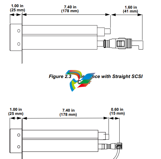
We recommend you mount the controller in a panel not more
than 0.2 in. (5 mm) thick.
1. Choose a panel location free from excessive heat (more
than 50°C), dust, and unauthorized handling. (Make sure
there is adequate clearance for the mounting hardware,
terminal blocks, and cables. The controller extends 7.40
in. (178 mm) behind the panel. Allow for an additional
0.60 to 1.60 in. (15 to 41 mm) beyond the connectors.
2. Temporarily cover any slots in the metal housing so that
dirt, metal filings, and pieces of wire do not enter the
housing and lodge in the electronics.
3. Cut a hole in the panel 1.80 in. (46 mm) by 3.63 in. (92
mm) as shown below. (This picture is NOT a template; it
is for illustration only.) Use caution; the dimensions given here have 0.02 in. (1 mm) tolerances.
4. Remove the brackets and collar from the processor module, if they are already in place.
5. Slide the processor module into the panel cutout.
Slide the mounting collar over the back of the processor
module, making sure the mounting screw indentations
face toward the back of the processor module.
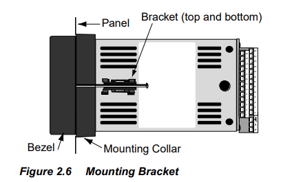
Loosen the mounting bracket screws enough to allow for
the mounting collar and panel thickness. Place each
mounting bracket into the mounting slots (head of the
screw facing the back of the processor module). Push
each bracket backward then to the side to secure it to the
processor module case.
Make sure the case is seated properly. Tighten the installation
screws firmly against the mounting collar to secure the unit.
Ensure that the end of the mounting screws fit into the
indentations on the mounting collar.
Mounting the MLS300-AIM
!
NOTE! If you plan to install scaling resistors, mount
them on the AIM-TB before mounting the
AIM-TB in the panel. See Chapter 9, Troubleshooting and Reconfiguring.
If you ordered an MLS300-AIM-TB with scaling inputs from Watlow Anafaze, the scaling
resistors are already installed.
Install the MLS300-AIM in a location free from excessive
(more than 50°C) heat, dust, and unauthorized handling.
The MLS300-AIM measures 6.5 L x 5 W x 7 in. H. Leave 6
in. of clearance above the MLS300-AIM, so you can remove
the entire unit (or just the AIM cards) if necessary.
1. Choose an appropriate place to install the MLS300-AIM.
2. Use the template shown in Figure 2.7 as a reference for
clearance and dimensions.
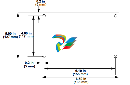
Figure 2.7 MLS300-AIM Template
3. Drill four holes for #6 or #8 screws in the chosen
location.
4. Place the MLS300-AIM where you will mount it. Use
screws with internal star lock washers to ensure a good
Frame Ground connection. You may use self-tapping
screws. Insert the screws through the standoffs and
tighten them.
5. Be sure to remove any loose metal filings after you are
finished mounting the MLS300-AIM.
Mounting the CIM300
!
NOTE! If you plan to install scaling resistors, mount
them on the CIM300 before mounting the
CIM300 in the panel. See Chapter 9, Troubleshooting and Reconfiguring.
If you ordered a CIM300 with scaling inputs from Watlow
Anafaze, the scaling resistors are already installed.
Install the CIM300 in a location free from excessive (more
than 50ºC) heat, dust and unauthorized handling. The CIM300
measures 7.5 L x 2.75 W x 3.75 inches D. Leave 1.5 inches of
clearance above the CIM300, so that there will be enough
space for power and communications wires.
DIN Mounting
1. Choose an appropriate place to install the CIM300.
2. Snap the CIM300 on to the DIN rail by placing the hook
side on the rail first, then pushing the snap latch side in place.
(To remove the CIM300 from the rail, use a flat-head screw
driver to unsnap the bracket from the rail.)
Direct Mounting
1. Choose an appropriate place to install the CIM300.
2. Use the dimensions shown in Figure 2.8 as a reference for
clearance and dimensions
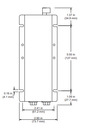
Figure 2.8 CIM300 Template
3. Drill four holes for #6 or #8 screws in the chosen location.
4. Place the CIM300 where you will mount it. Use screws with
internal star lock washers to ensure a good frame ground
connection. You may use self-tapping screws. Insert the
screws through the standoffs and tighten them.
5. Be sure to remove any loose metal filings after you are
finished mounting the CIM300.
Do not connect power or sensors to the
MLS300 now. Test the unit first, as explained
in the Power Wiring and Controller Test section.
Mounting the TB50
There are two ways you can mount the TB50: use the preinstalled DIN rail mounting brackets provided or use the
plastic standoffs. Follow the corresponding procedures to
mount the board
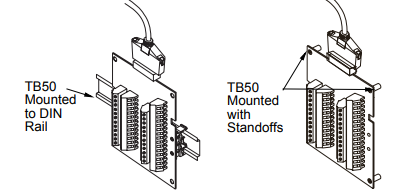
DIN Rail Mounting
Snap the TB50 on to the DIN rail by placing the hook side on
the rail first, then pushing the snap latch side in place. Refer
to Figure 2.10.

Figure 2.10 TB50 Mounted on a DIN Rail (Front)
To remove the TB50 from the rail, use a flat-head screw driver
to unsnap the bracket from the rail. See Figure 2.11
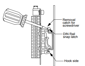
Figure 2.11 TB50 Mounted on DIN Rail (Side)
Mounting with Standoffs
1. Remove the DIN rail mounting brackets from the TB50.
2. Select a location with enough clearance to remove the
TB50, its SCSI cable, and the controller itself.
3. Mark the four mounting holes.
4. Drill and tap the 4, #6 (3.5 mm) mounting holes.
5. Mount the TB50 with 4 screws.
There are four smaller holes on the terminal board. Use these
holes to secure wiring to the terminal block with tie wraps.
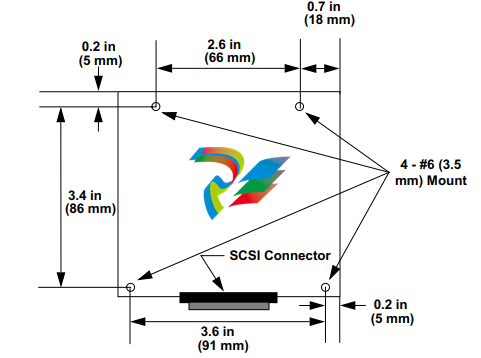
Figure 2.12 Mounting a TB50 with Standoffs
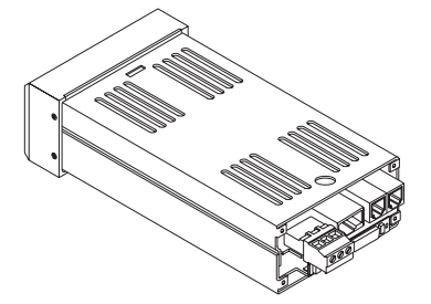
Mounting the Power Supply
If you use your own power supply for the MLS300, please
refer to the power supply manufacturer's instructions for
mounting information. Choose a power supply that supplies
an isolated regulated 12 to 24 Vdc at 1 A.
Mounting Environment
Leave enough clearance around the power supply so that it
can be removed.
Mounting DAC or SDAC Module
This section describes how to install the optional DAC and
SDAC Digital-to-Analog Converters for use with a MLS300
series controller.
Installation
Installation of the DAC and SDAC is essentially the same.
The main differences are in the dimensions and the wiring.
Follow this procedure to correctly install these devices.
Jumpers
The output signal range of the DAC and SDAC modules is
configured with jumpers. See Configuring DAC Outputs on
page 210 and Configuring SDAC Outputs on page 212 for
information on setting these jumpers.
Mounting
1. Select a location for installation. The unit is designed for
wall mounting and should be installed as close to the controller as possible.
2. Mark and drill four holes for screw mounting. Holes
accommodate #6 size screws. Use the diagrams in Figure
2.14 on page 32 for the correct locations.
3. Install the unit with the four screws.
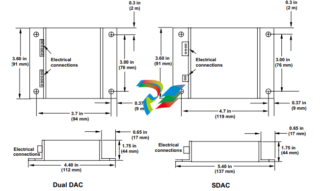
Figure 2.14 Dual DAC and SDAC Dimensions
System Wiring
Successful installation and operation of the control system can
depend on placement of the components and on selection of
the proper cables, sensors, and peripheral components.
Routing and shielding of sensor wires and proper grounding
of components can insure a robust control system. This
section includes wiring recommendations, instructions for
proper grounding and noise suppression, and considerations
for avoiding ground loops.
Never wire bundles of low power Watlow
Anafaze circuits next to bundles of high power ac wiring. Instead, physically separate
high power circuits from the controller. If
possible, install high voltage ac power circuits in a separate panel.
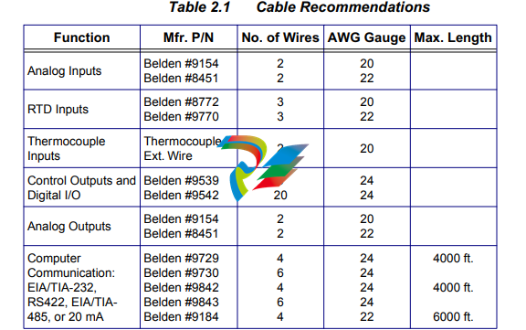
Wiring Recommendations
Keep the following guidelines in mind when selecting wires
and cables:
• Use stranded wire. (Solid wire can be used for fixed
service; it makes intermittent connections when you
move it for maintenance.)
• Use #20 AWG thermocouple extension wire. Larger or
smaller sizes may be difficult to install, may break easily,
or may cause intermittent connections.
• Use shielded wire. (The electrical shield protects the
signals and the MLS300 from electrical noise.) Connect
one end of the input and output wiring shield to earth
ground.
• Use copper wire for all connections other than
thermocouple sensor inputs.
See Table 2.1 on page 33 for cable recommendations.
Noise Suppression
The MLS300’s outputs are typically used to drive solid state
relays. These relays may in turn operate more inductive types
of loads such as electromechanical relays, alarm horns and
motor starters. Such devices may generate electromagnetic
interference (EMI or noise). If the controller is placed close to
sources of EMI, it may not function correctly. Below are some
tips on how to recognize and avoid problems with EMI.
For the AIM or CIM300 earth ground wire, use a large gauge
and keep the length as short as possible. Additional shielding
may be achieved by connecting a chassis ground strap from
the panel to the case of the processor module.
Symptoms of RFI/EMI
If your controller displays the following symptoms, suspect
EMI:
• The controller's display blanks out and then re-energizes
as if power had been turned off for a moment.
• The process variable does not display correctly.
EMI may also damage the digital output circuit—so digital
outputs will not turn on. If the digital output circuit is
damaged, return the controller to Watlow Anafaze for repair.
Avoiding Noise Problems
To avoid RFI/EMI noise problems:
• The MLS300 system includes noise suppression
circuitry. Some of which is only effective when the
components are properly grounded. Be sure the
processor module and AIM (or CIM300) are connected
to earth ground.
• Separate the 120 or 240 Vac power leads from the low
level input and output leads connected to the MLS300
series controller. Don't run the digital I/O or control
output leads in bundles with 120 Vac wires.
• Where possible, use solid-state relays (SSRs) instead of
electromechanical (EM) relays. If you must use EM
relays, try to avoid mounting them in the same panel as
the MLS300 series equipment.
• If you must use EM relays and you must place them in a
panel with MLS300 series equipment, use a 0.01
microfarad capacitor rated at 1000 Vac (or higher) in
series with a 47 Ω, 1/2 watt resistor across the NO
contacts of the relay load. This is known as a snubber
network and can reduce the amount of electrical noise.
• You can use other voltage suppression devices, but they
are not usually required. For instance, you can place a
metal oxide varistor (MOV) rated at 130 Vac for 120 Vac
control circuits across the load, which limits the peak AC
voltage to about 180 Vac (Watlow Anafaze P/N 0802-
0826-0000). You can also place a transorb (back to back
zener diodes) across the digital output, which limits the
digital output voltage.
The above steps will eliminate most EMI/RFI noise problems.
If you have further problems or questions, please contact
Application Engineering
Avoiding Ground Loops
Ground loops occur when current passes from the process
through the controller to ground. This can cause instrument
errors or malfunctions.
A ground loop may follow one of these paths, among others:
• From one sensor to another.
• From a sensor to the communications port.
• From a sensor to the dc power supply.
The best way to avoid ground loops is to minimize
unnecessary connections to ground. Do not connect any of the
following terminals to each other or to earth ground:
• MLS300 PM: TB1, pin 2 (COM)
• MLS300-AIM: TB3, pin 1 to (PWR COM)
• All A COM terminals on the MLS300-AIM or CIM300
• Power Supply: (COM)
• Pin 3 on the RJ connector
Watlow Anafaze strongly recommends that you:
• Isolate outputs through solid state relays, where possible.
• Isolate RTDs or “bridge” type inputs from ground.
• Isolate digital inputs from ground through solid state
relays. If you can't do that, then make sure the digital
input is the only place that one of the above pins connects
to earth ground.
• If you are using EIA/TIA-232 from an un-isolated host,
don't connect any other power common point to earth
ground, or use an optical isolator in the communications
line.
Personal Computers and Ground Loops
Many PC communications ports connect the communications
common to chassis ground. When such a PC is connected to
the controller, this can provide a path to ground for current
from the process that can enter the controller through a sensor
(such as a thermocouple). This creates a ground loop that can
affect communications and other controller functions. To
eliminate a ground loop, either use an optically isolated
communications adapter or take measures to ensure that
sensors and all other connections to the controller are isolated
and not conducting current into the unit.
Power Connections
This section covers making the power connections between
the MLS300 components and testing those connections before
completing sensor and controller wiring in the following
sections.
Figure 2.15 on page 36 and Figure 2.16 on page 36 illustrates
the power connections.
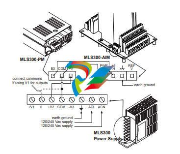
Figure 2.15 Power Connections with MLS300-
AIM
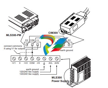
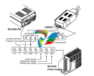
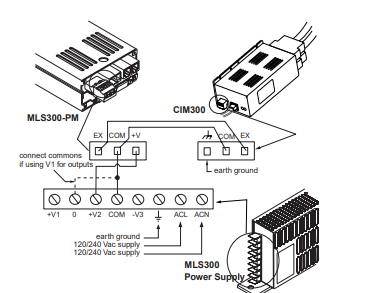
Figure 2.16 Power Connections with CIM300
At this point you have isolated the parts of
the MLS300 that can be damaged by excess
voltage.
4. With ac power on, use a voltmeter to measure the
following:
(a) The voltage between the COM and +V terminals
on TB 1 should be +12 to 24 Vdc
(b) The voltage between COM and EX should be 0
Vdc
5. If the voltages are not as described in Step 4, check the
installation of the power supply, troubleshoot or replace
the power supply. If the voltages are within the limits
described in Step 4, continue to Step 6.
6. Turn off the power and plug TB1 back into the MLS300-
PM.
7. Turn the power back on. The Processor Module's display
should light up, and after about a second the Bar Graph
display should appear, followed by the message AIM
COMM FAIL.
8. Verify power to the MLS300-AIM. With a voltmeter,
measure the following:
(a) The voltage between +5 IN and PWR COM terminals on TB-3 on the MLS300-AIM should be
+4.75 to +5.25 Vdc.
9. If the voltage is not as described in Step 8, check the
wiring from the MLS300-PM to the MLS300-AIM. If
the voltage is within the limit described in Step 8,
continue to Step 10.
10. Turn off the power and carefully insert the AIM cards
back into the AIM Terminal Block.
11. Reconnect the AIM communications cable.
-
 HIRSCHMANN MSM20-M2M2M2M2SY9HH9E Ethernet media modul
 -
 HIRSCHMANN SPIDER-PL-20-05T1999999TWVHHHH Industrial Ethernet Rail Switch
 -
 Hirschmann SPIDER-PL-20-07T1M2M299TWVHHHH Industrial ETHERNET Rail Switch
 -
.png) Hirschmann (Belden) RS20-1600M2M2SDAEHC09.1.00 DIN-rail managed industrial Fast Ethernet switch
Hirschmann (Belden) RS20-1600M2M2SDAEHC09.1.00 DIN-rail managed industrial Fast Ethernet switch -
 Hirschmann (Belden) RS30-1602O6O6TDAPHC09.1.00 DIN-rail managed industrial Ethernet switch
 -
 Hirschmann (Belden) RS30-2402O6T1SDAPHH09.0.13 DIN-rail industrial Ethernet switch
 -
Hirschmann (Belden) SPIDER-PL-20-04T1S29999TY9HHHH Ethernet DIN-rail switch
-
 HIRSCHMANN RS20-1600T1T1SDAUHX Switch
 -
 HIRSCHMANN BRS42-0012OOOO-SPCZ99HHSES industrial switch
 -
 Hirschmann RS20-0800S2S2TDHPHH09.0.14 Fast Ethernet DIN rail switch.
 -
 HIRSCHMANN MM20-Z6Z6M2M2SAHH Hybrid Fast Ethernet Media Module
 -
 HIRSCHMANN MM20-Z6Z6T1T1SAHH hot-swappable hybrid Fast Ethernet Media Module
 -
 HIRSCHMANN MM20-P9P9T1T1SAHH Hybrid Fast Ethernet Media Module
 -
 HIRSCHMANN MM20-M4T1T1T1SAHH Hybrid Fast Ethernet Media Module
 -
 HIRSCHMANN MM20-M4M4T1T1SAHH Hybrid Fast Ethernet Media Module
 -
 HIRSCHMANN MM20-M2M2M2M2SZHH Ethernet media module
 -
HIRSCHMANN MM20-M2M2M2M2SAHH Ethernet media module
-
 HIRSCHMANN MM20-T1T1T1T1EBH 4-port Fast Ethernet Copper Cable Media Module
 -
HIRSCHMANN MM20-T1T1T1T1SAHH 4-port Fast Ethernet Copper Cable Media Module
-
HIRSCHMANN MM20-T1T1T1T1SAHH 4-port Fast Ethernet Copper Cable Media Module
-
 HIRSCHMANN MM20-Z6Z6EBH Hot-swappable fast Ethernet media module
 -
 HIRSCHMANN MM20-Z6Z6SAHH Ethernet media module
 -
HIRSCHMANN MM20-Z6Z6Z6Z6EBH Industrial Media Module
-
 MSM40-T1T1T1TZ9HH9E99.9.99 HIRSCHMANN Switch
 -
 HIRSCHMANN MS20-0800SAAEHC / MS20-0800SAAEHC0 8-port modular Layer 2 management Ethernet switch
 -
 Hirschmann RSPM20-4T14T1SZ9HHS9 Switch RSPM20-4T14T1SZ9HHS9
 -
 HIRSCHMANN RS20-1600M2M2SDAEHH09.1. RS20/30/40 Managed Switch configurator
 -
HIRSCHMANN RS20-1600M2M2SDAEHX09.0.00 Ethernet switch
-
 HIRSCHMANN BELDEN SPIDER-PL-20-07T1M2M299TY9HHHH / SPIDERPL2007T1M2M299TY9HHHH
 -
HIRSCHMANN MM3-1FXS2/3TX1 Switching Board Module
-
 HIRSCHMANN RSPE30-24044O7T99-ECCP999HHSE2A08.1.00 Industrial-grade fanless management-type Ethernet switch
 -
 HIRSCHMANN RS30-1602OOZZSDAEHC09.1.00 DIN-rail-mounted managed Layer 2 Ethernet switch
 -
 HIRSCHMANN MACH104-20TX-F Managed 24-port Full Gigabit 19" Switch
 -
 HIRSCHMANN Switch RS20-0800M4M4SDAE
 -
Hirschmann RS30-1602O6O6SDAEHH09.1. Management-type Ethernet switch
-
 Hirschmann RS30-1602OOZZSDAEHC09.0.10 Open rack-style Ethernet switch
 -
 HIRSCHMANN RSPE30-24044O7T99-SCCV999HHSI2SXX.X.XX High-Availability Seamless Redundancy
 -
HIRSCHMANN RSPE30-24044O7T99-SCCZ999HHSE2A DIN-rail Ethernet switch
-
HIRSCHMANN MM2-4TX1-EEC switch
-
HIRSCHMANN MSM40-T1T1T1T1TZ9HH9E99.9.99 Module
-
 HIRSCHMANN RS20 Rail Switch RS20-0400S4T1SDAEHC07.1.01
 -
 HIRSCHMANN M4-FAST8-SFP Fast Ethernet media module
 -
 HIRSCHMANN RS20-0400M2T1SDAP Managed Fast-Ethernet-Switch
 -
 HIRSCHMANN BELDEN SPIDER II 8TX/1FX EEC Industrial Ethernet Rail Switch
 -
HIRSCHMANN MM3-2FXS2/2TX1
-
 HIRSCHMANN RS2-4TX/1FX EEC Industrial Ethernet Rail Switch
 -
 RS30-0802O6O6SDAEHC09.0.10 HIRSCHMANN Switch
 -
 HIRSCHMANN m4-8TP-RJ45 Ethernet Media Module
 -
 HIRSCHMANN MSP30-24040SCZ9URHHE3A switch
 -
 Hirschmann rack MS30-1602SAAPHC
 -
 HIRSCHMANN RS2-FX/FX Industrial Switch Module
 -
Rs1txfx - Hirschmann - Rs1-Tx/Fx Rail Switch
-
RS20-0800S2S2SDAEHC09.1.00 HIRSCHMANN Commutator
-
 Hirschmann EAGLE20 TX/TX Industrial Security Router
 -
 Hirschmann SPIDER-SL-20-04T1S29999SY9HHHH Industrial Switch
 -
 HIRSCHMANN MAR1040-4C4C4C4C9999SMMHRHHXX.X. Gigabit Ethernet Switch configurator
 -
 Hirschmann MAR1040 Industrial Switch
 -
 HIRSCHMANN BELDEN RS30-1602O6O6SDAE
 -
Hirschmann RS20-1600M2M2SDAUHC Ethernet DIN rail switch
-
 HIRSCHMANN OCTOPUS 24M industrial switch
 -
 HIRSCHMANN RS20-1600T1T1SDAE Management-type Ethernet switch
 -
 HIRSCHMANN RS20-1600T1T1SDAUHH industrial switch
 -
HIRSCHMANN RS20-0800M2M2SDAPHC09.0.04 switch
-
 Hirschmann MR 8-03 24V DC Industrial Modular Bridge/Router
 -
 HIRSCHMANN RS20-0400M2T1SDAPHC08.0.01 Managed Switch
 -
 MACH1130 Hirschmann Industrial Switch
 -
 HIRSCHMANN 943824-002 SPIDER 5TX Industrial Ethernet Switch
 -
 HIRSCHMANN RS30-0802O6O6SDAEHC09.1.00 Managed Industrial Switch
 -
 HIRSCHMANN RS20-0400M2M2TDAEHC04.0.01 Industrial Switch
 -
 HIRSCHMANN BRS20-0600Z6Z6-STCZ99HHSES Industrial Switch
 -
 HIRSCHMANN MACH104-20TX-FR-L3P Industrial Ethernet Switch
 -
 HIRSCHMANN RS40-0009CCCCEDBPHH06.0.01 Industrial Switch
 -
 HIRSCHMANN RS2-3TX/2FX EEC Industrial Ethernet Switch
 -
 Hirschmann MACH 1020/1030 Fast/Gigabit Rack Mount Switches
 -
HIRSCHMANN RS20-0800M2M2SDAPHC09.0.14 Industrial Switch
-
 HIRSCHMANN RS20-1600T1T1SDAEHC09.0.04 Industrial Switch
 -
 HIRSCHMANN RSB20-0800T1T1EAABHH Industrial Switch
 -
 HIRSCHMANN MACH4002-48+4G-L3E Industrial Backbone Switch
 -
 HIRSCHMANN RS20-0400S2T1SDAE Industrial Managed Switch
 -
HIRSCHMANN RS20-0800S2T1SDAUHC Industrial Switch
-
 HIRSCHMANN RS20-2400S4S4SDAEHC09.0.14 industrial switch
 -
 HIRSCHMANN OS20-001200T5T5T5- TBBZ999HHNE3S 08.1.00 industrial switch
 -
HIRSCHMANN OS20-001200T5T5T5- TBBZ999HHNE3S 08.1.00 industrial switch
-
 HIRSCHMANN RS40-0009CCCCSDAEHH09.0.14 switch
 -
 Hirschmann RS20-1600T1T1SDAUHC Management-type Ethernet Switch
 -
 Hirschmann M1-8SFP Switche
 -
Hirschmann Industrial Ethernet Ruggedized Switch MACH1000 Family
-
 Basler Electric, Solid State Protective Relay, BE1-60
 -
BASLER ELECTRIC SR4A-2B15B3A Static Voltage Regulator
-
.png) BASLER ELECTRIC EXCITER DIODE MONITOR EDM-200
BASLER ELECTRIC EXCITER DIODE MONITOR EDM-200 -
.png) BASLER ELECTRIC DECS125-15-B2C5 DIGITAL EXCITATION CONTROL SYSTEM V 2.0.9
BASLER ELECTRIC DECS125-15-B2C5 DIGITAL EXCITATION CONTROL SYSTEM V 2.0.9 -
 BASLER ELECTRIC BE1-851 OVERCURRENT PROTECTION RELAY MECHANISM
 -
 Basler Electric BE1-51A / BE151A
 -
 Basler Electric BE1-40Q Loss of Excitation Relay
 -
 Basler Electric BE1-87G Variable Percentage Differential Relay
 -
 Basler Electric BE1-11 Protection System I5A3M2P2N0EA00
 -
 BASLER ELECTRIC DECS-200-1C Digital Excitation Control System
 -
 Basler Electric / Kohler BE1-11g Generator Protection Relay G5A3M2J2N0E000
 -
BASLER ELECTRIC DECS125-15 DIGITAL EXCITATION CONTROL SYSTEM
-
 BASLER ELECTRIC BE1-951 OverCurrent Protecton System
 -
Basler Electric DECS-200-1L Digital Excitation Control System
-
 Basler Electric DGC-2020HD-5NS1DNSBA Digital Genset Controller -
 -
 BASLER ELECTRIC BE1-81T1EE1WA0N1F / BE181T1EE1WA0N1F
 -
 BASLER ELECTRIC BE1-25M1EA6PN5R1F / BE125M1EA6PN5R1F
 -
 BASLER ELECTRIC DECS-250-LN1SN1N DIGITAL EXCITATION CONTROL SYSTEM
 -
Basler Electric DECS-250-CN2CN 1N Digital Excitation Control System Unit
-
 BASLER ELECTRIC DECS-300-C0N0 DIGITAL EXCITATION CONTROL SYSTEM
 -
 BASLER ELECTRIC BE1-87T-A1E-A1J-D0S1F / BE187TA1EA1JD0S1F
 -
BASLER ELECTRIC BE1-11-G6D1M0J2P0E000 Protection System
-
 BASLER ELECTRIC BE1-GPS100-E4N1H1N GENERATOR PROTECTION SYSTEM
 -
 Jaquet Relay card (Auxiliary module) FTV 3090 377Z-03985
 -
 Jaquet Trip Chain Control card FTBU 3034 377Z-05030
 -
 Jaquet with input card -E04 FTFU 3024 -E04 377Z-05855
 -
 Jaquet with input card -E03 FTFU 3024- E03 377Z-03983
 -
 Jaquet FTFU 3024- E02 377Z-03982 with input card -E02
 -
 Jaquet FTFU 3024-E01 377Z-03981 with input card -E01
 -
 Hirschmann RS20-2400T1T1SDAE Industrial Managed Ethernet Switch
 -
 Hirschmann BELDEN EAGLE30-04022O6TT999SCCV9HSE3F
 -
 Hirschmann MM3-2FXS2/2TX MICE Media Module
 -
 Hirschmann RS20-1600M2M2SDAPHC08.0.05 Industrial Managed Switch
 -
 Hirschmann OZD Profi 12M G12-1300 PRO Fieldbus Repeater
 -
Hirschmann SPIDER 4TX/1FX-ST EEC Industrial Ethernet Switch
-
 Hirschmann MM2-2FXM3/2TX1 MICE Media Module
 -
 Hirschmann RS20-2400M2M2SDAPHC09.0.14 Industrial Switch
 -
 Hirschmann RS20-0400M2M2SDAEHC07.1.05 OpenRail Switch
 -
 Hirschmann OZD Profi 12M G12-EEC Fieldbus Repeater
 -
HIRSCHMANN MDA422-1/2-3.5c-23/46 sensor
-
Hirschmann RS30-2402T1T1SDAUHC Managed Industrial Switch


