
GEMotor Protection System Integrated process, control, and protection for low voltage motors
featured protection for low voltage AC motors
• Advanced automation capabilities providing customized
protection and integrated automation control
• Cost effective solution - Low cost modular design
• Small footprint and compact design - With or without
display, fits into standard MCC buckets
• Preconfigured logic for all standard motor starter types,
EnerVistaTM compatible
• Integrated motor control pushbuttons
• Remote monitoring via serial communications, Modbus RTU
• Easy installation and integration - Panel mount option
• Reduced number of devices - Replaces bi-metal overload
elements, integrates timers, relays, meters, switches,
indicators
• Motor protection and management system for low voltage
AC motors
• Specifically designed for Motor Control Centre applications
• Motor operational parameters and historical data
• Process data
• Phase and ground current, power, energy, voltage
• Status of relay inputs
• Trip record and pre-trip values
• Motor statistical information
Monitoring and Metering
User Interface
Protection and Control
• Motor Thermal Model
• Single phase / Current unbalance
• Contactor failure
• Locked/stalled rotor
• Ground fault
• Undervoltage, Overvoltage
• Overtemperature
• Acceleration Trip
• Thermistor Protection
• Starts per Hour / Time Between Starts
• Undercurrent and underpower
• Configurable motor start controller
• Undervoltage auto restart
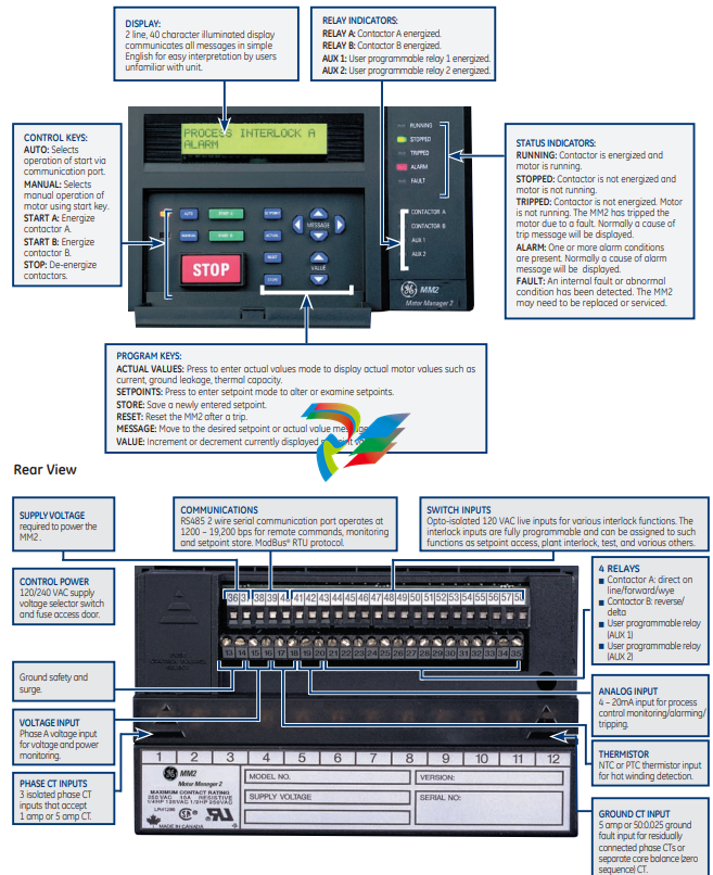
• 40 Character LCD display
• Front Panel control push buttons and programming keypad
• 11 Motor and Relay Status LED’s
• RS485 ModBus™ , 1200 - 19,200 bps
Motor Protection System
Integrated process, control, and
protection for low voltage motors
Features
Applications
K
EnerVistaTM Software
• State of the art software for configuration and
commissioning GE Multilin products
• Document and software archiving toolset to ensure
reference material and device utilities are up-to-date
• EnerVistaTM Integrator providing easy integration of data
in the MM2 into new or existing monitoring and control
systems
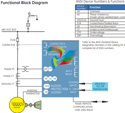
Protection and Control
The MM2 is a digital motor protection
system designed to protect and manage
low voltage motors and driven equipment.
It contains a full range of selectively
enabled, self contained protection and
control elements as detailed in the
Functional Block Diagram and Features
table.
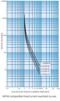
Thermal Overload
An overload trip occurs when the
thermal capacity value equals 100%.
Thermal capacity used is calculated from
accumulated I2t value and chosen
overload curves. True RMS current sensing
ensures correct response to the heating
effect of harmonics. One of 12 different I2t
time overcurrent overload curves may be
selected from eight standard curves and
four NEMA compatible curves.
Phase Unbalance
The MM2 monitors the percentage
unbalance in the motor phase currents. If
a phase current unbalance of greater than
15% exists for more than five seconds an
alarm is generated. If a phase current
unbalance of greater than 30% exists for
more than five seconds a single phase trip
occurs.
Locked/Stalled Rotor
To help prevent damage to mechanical
equipment such as pumps or fans, the
MM2 will trip when the running current
exceeds the stalled rotor trip level after the
programmed time delay. This feature may
be set to ‘OFF’ if desired, and it is disabled
during motor starting.
Ground Fault
The ground fault level is measured as a
percentage of the CT primary. Ground
overcurrent can be detected either from
the residual connection of the phase
CTs or from a zero sequence CT. A delay
time is set to prevent false alarms from
momentary surges. Both a ground fault
alarm and trip are provided. The alarm
can be set below the trip level to provide
an early warning of insulation breakdown.
Overtemperature
An input from motor winding thermistors
is available. The MM2 can accept both
positive temperature coefficient (PTC) and
negative temperature coefficient (NTC)
sensors. A thermistor level can be selected
for both alarm and trip.
Cooling Time
After an overload trip, the thermal
capacity value decreases exponentially
to model the motor cooling characteristic.
An overload trip can be reset when the
thermal capacity value decreases to 15%.
A stopped motor cooling time can be set to
determine how long it takes for a stopped
motor to reach steady state ambient
temperature from its maximum allowable
temperature.
Undercurrent/Underpower
Both undercurrent and underpower alarms
and trips are provided with time delays.
Protection against failed shear pin or loss
of pump flow, which may result in only a
small change in current, is provided by the
underpower alarm.
Undervoltage
For voltage sensitive loads, a drop in
voltage increases the drawn current,
which may cause overheating in the
motor. The undervoltage protection
feature can be used to either cause a trip
or generate an alarm when the voltage
drops below a specified voltage setting for
a programmable time delay.
Overvoltage
An overvoltage on running motor with a
constant load results in decreased current.
However, iron and copper losses increase,
causing an increase in motor temperature.
The current overload relay will not pickup
this condition and provide adequate
protection. The overvoltage element may
be used for protecting the motor in the
event of a sustaine overvoltage condition.
Contactor Failure
The MM2 monitors the contactor while
performing start and stop commands. If
the contactor does not change status an
‘open control circuit’ or ‘welded contactor’
alarm is triggered.
Additional Alarms
The MM2 has programmable alarms to
warn of a number of abnormal conditions.
These include: acceleration time exceeded,
abnormal inverter starter, incomplete start,
motor greasing, contactor inspection,
motor stop time, analog input, and process
interlock switch open.
Starters
MM2 can be programmed to serve as the
following types of motor starters:
• Full Voltage non-reversing,
• Full Voltage reversing,
• Wye/Delta open or close transition
starter,
• Two speed starter,
• Inverter (VSD) starter,
• Slip ring (rotor resistors) and primary
resistance starters,
• Autotransformer open or close
transition starter,
• Duty/Standby starter,
• Soft starter
Undervoltage Auto Restart
The motor can be automatically restarted
after a momentary power loss when this
feature is enabled. When the control
voltage drops below the dropout voltage
the contactors are de-energized. The MM2
can initiate timers to restart selected drives
upon the return of supply voltage. If control
voltage is restored within the programmed
restart time, the motor will be restarted
immediately. If the control voltage takes
longer to be restored, the MM2 can be
programmed to attempt a restart after a
programmed time delay.
Outputs
The MM2 has one or two contactors (A
and B) which are used for motor starting.
There are also two auxiliary programmable
output relays available on the MM2,
which can be assigned to any one of 31
functions.
Switched Inputs
The MM2 has up to six fixed control inputs.
These are used for start A and B, stop, local
isolator, and contactor A and B status. The
MM2 also has up to 10 programmable
switch inputs. Each input can have one
of 33 interlock functions assigned to it. A
function can be assigned to one interlock
input only.
Analog Input
The analog input can be scaled to user
defined values. High and low alarm and trip
setpoints are recorded with time delays.
Monitoring and Metering
The MM2 offers advanced monitoring and
metering which includes:
Metering
The MM2 meters and displays:
• current of each phase
• Ground fault leakage current
• Motor load as a % of full load current
• Thermal capacity used (%)
• % Current unbalance
• Power (kW)
• Energy (kWh)
• Voltage
• Analog input
Trip Record
When the MM2 issues a trip command a
record is generated which includes the
cause and pre-trip actual values.
Statistics and Maintenance
The MM2 records statistical data about
relay and motor operation, allowing the
user to set the interval at which routine
maintenance tasks should be performed.
When the times are exceeded an alarm is
generated. These include:
• Motor greasing interval: number of
hours between bearing lubrication
• Contactor inspection: number of starts
after which the contactor contacts
must be inspected for wear
• Maximum motor stopped time: the
maximum number of hours the motor
can be left shut down
User Interfaces
When ordered with the Panel Mount
option, the MM2 comes equipped with a 40
character display, LED indicators, as well
programming and control push buttons.
Display and Keypad
The MM2 has a keypad and 40 character
display for local control and programming
without a computer. In the event of a
trip, alarm, or start block, the display will
automatically display a clear status
message.
In addition to the programming keys, the
panel mount option also provides 3 control
keys for starting and stopping the motor
locally.
Indicator LEDs
The panel mount MM2 has nine LED’s that
provide the status of the motor and relay
output contacts. Two additional LED’s
indicate whether the relay is in Auto or
Manual control mode.
Communications
The MM2 uses a ModBus® RTU RS485
connection for communication. Up to 32
MM2s can be daisy-chained together on a
single communication channel. The MM2
supports a number of baud rates, ranging
from at 1200 to 19,200 bps. A RS232/485
converter module may be used to connect
a personal computer to the MM2.
Software
The MM2 comes with a Windows®-based
configuration program called MM2PC. It
allows access to all the features of the
MM2 with easy to use, pull-down menus.
Using this program it is possible to:
• Program or modify setpoints
• Load or save setpoints from or to a
disk
• Read actual values from the MM2
• Monitor status
• Read pre-trip data and trip record
• Display dynamic trending of actual values
• Get help on any topic
• Print the instruction manual from disk
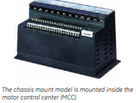
Mounting Configurations
The MM2 can be ordered as either a chassis
mount or panel mount relay.
The chassis mount comes with all of the
standard features and may be ordered
with one or both of the option packages.
Setpoints are loaded through the RS485
port using the MM2 PC Setup program.
The panel The MM2 Panel Mount (PD)
option is available when both of the option
packages have been ordered. The panel
mount MM2 is mounted through the front
panel of the MCC, providing complete local
programming and control.
Option Packages
Option package 1 increases the control and
diagnostic features available. It includes:
• Process control and process inputs
• Undervoltage auto restart
• Enhanced diagnostics including alarms,
pre-trip data, and historical statistics
about the use and performance of the
motor and drive
Option package 2 increases the protection
features and input options. It includes:
• Second contactor control, including two
more control inputs
• Single-phase VT input used to calculate
and display the kW and kWh absorbed
by the drive
• Enhanced protection including five
more protection features
• Motor winding thermistor input
EnerVistaTM Software
The EnerVista™ Suite is an industry
leading set of software programs that will
simplify every aspect of using the MM2
relay. Tools to monitor the status of your
motor, maintain your relay, and integrate
information measured by the MM2 into
HMI or SCADA monitoring systems are
available.
EnerVistaTM Launchpad
EnerVista™ Launchpad is a powerful
software package that provides users with
all of the setup and support tools needed
for configuring and maintaining GE Multilin
products. Launchpad allows configuring
devices in real-time by communicating
using serial, Ethernet , or modem
connections, or offline by creating setting
files to be sent to devices at a later time.
Included in Launchpad is a document
archiving and management system
that ensures critical documentation is
up-to-date and available when needed.
Documents made available include:
• Manuals
• Application Notes
• Guideform Specifications
• Brochures
• Wiring Diagrams
• FAQ’s
• Service Bulletins
Viewpoint Monitoring
Viewpoint Monitoring is a powerful yet
simple-to-use monitoring and data
recording package for small systems.
Viewpoint Monitoring provides a
complete HMI package with the following
functionality
-
 HIRSCHMANN MSM20-M2M2M2M2SY9HH9E Ethernet media modul
 -
 HIRSCHMANN SPIDER-PL-20-05T1999999TWVHHHH Industrial Ethernet Rail Switch
 -
 Hirschmann SPIDER-PL-20-07T1M2M299TWVHHHH Industrial ETHERNET Rail Switch
 -
.png) Hirschmann (Belden) RS20-1600M2M2SDAEHC09.1.00 DIN-rail managed industrial Fast Ethernet switch
Hirschmann (Belden) RS20-1600M2M2SDAEHC09.1.00 DIN-rail managed industrial Fast Ethernet switch -
 Hirschmann (Belden) RS30-1602O6O6TDAPHC09.1.00 DIN-rail managed industrial Ethernet switch
 -
 Hirschmann (Belden) RS30-2402O6T1SDAPHH09.0.13 DIN-rail industrial Ethernet switch
 -
Hirschmann (Belden) SPIDER-PL-20-04T1S29999TY9HHHH Ethernet DIN-rail switch
-
 HIRSCHMANN RS20-1600T1T1SDAUHX Switch
 -
 HIRSCHMANN BRS42-0012OOOO-SPCZ99HHSES industrial switch
 -
 Hirschmann RS20-0800S2S2TDHPHH09.0.14 Fast Ethernet DIN rail switch.
 -
 HIRSCHMANN MM20-Z6Z6M2M2SAHH Hybrid Fast Ethernet Media Module
 -
 HIRSCHMANN MM20-Z6Z6T1T1SAHH hot-swappable hybrid Fast Ethernet Media Module
 -
 HIRSCHMANN MM20-P9P9T1T1SAHH Hybrid Fast Ethernet Media Module
 -
 HIRSCHMANN MM20-M4T1T1T1SAHH Hybrid Fast Ethernet Media Module
 -
 HIRSCHMANN MM20-M4M4T1T1SAHH Hybrid Fast Ethernet Media Module
 -
 HIRSCHMANN MM20-M2M2M2M2SZHH Ethernet media module
 -
HIRSCHMANN MM20-M2M2M2M2SAHH Ethernet media module
-
 HIRSCHMANN MM20-T1T1T1T1EBH 4-port Fast Ethernet Copper Cable Media Module
 -
HIRSCHMANN MM20-T1T1T1T1SAHH 4-port Fast Ethernet Copper Cable Media Module
-
HIRSCHMANN MM20-T1T1T1T1SAHH 4-port Fast Ethernet Copper Cable Media Module
-
 HIRSCHMANN MM20-Z6Z6EBH Hot-swappable fast Ethernet media module
 -
 HIRSCHMANN MM20-Z6Z6SAHH Ethernet media module
 -
HIRSCHMANN MM20-Z6Z6Z6Z6EBH Industrial Media Module
-
 MSM40-T1T1T1TZ9HH9E99.9.99 HIRSCHMANN Switch
 -
 HIRSCHMANN MS20-0800SAAEHC / MS20-0800SAAEHC0 8-port modular Layer 2 management Ethernet switch
 -
 Hirschmann RSPM20-4T14T1SZ9HHS9 Switch RSPM20-4T14T1SZ9HHS9
 -
 HIRSCHMANN RS20-1600M2M2SDAEHH09.1. RS20/30/40 Managed Switch configurator
 -
HIRSCHMANN RS20-1600M2M2SDAEHX09.0.00 Ethernet switch
-
 HIRSCHMANN BELDEN SPIDER-PL-20-07T1M2M299TY9HHHH / SPIDERPL2007T1M2M299TY9HHHH
 -
HIRSCHMANN MM3-1FXS2/3TX1 Switching Board Module
-
 HIRSCHMANN RSPE30-24044O7T99-ECCP999HHSE2A08.1.00 Industrial-grade fanless management-type Ethernet switch
 -
 HIRSCHMANN RS30-1602OOZZSDAEHC09.1.00 DIN-rail-mounted managed Layer 2 Ethernet switch
 -
 HIRSCHMANN MACH104-20TX-F Managed 24-port Full Gigabit 19" Switch
 -
 HIRSCHMANN Switch RS20-0800M4M4SDAE
 -
Hirschmann RS30-1602O6O6SDAEHH09.1. Management-type Ethernet switch
-
 Hirschmann RS30-1602OOZZSDAEHC09.0.10 Open rack-style Ethernet switch
 -
 HIRSCHMANN RSPE30-24044O7T99-SCCV999HHSI2SXX.X.XX High-Availability Seamless Redundancy
 -
HIRSCHMANN RSPE30-24044O7T99-SCCZ999HHSE2A DIN-rail Ethernet switch
-
HIRSCHMANN MM2-4TX1-EEC switch
-
HIRSCHMANN MSM40-T1T1T1T1TZ9HH9E99.9.99 Module
-
 HIRSCHMANN RS20 Rail Switch RS20-0400S4T1SDAEHC07.1.01
 -
 HIRSCHMANN M4-FAST8-SFP Fast Ethernet media module
 -
 HIRSCHMANN RS20-0400M2T1SDAP Managed Fast-Ethernet-Switch
 -
 HIRSCHMANN BELDEN SPIDER II 8TX/1FX EEC Industrial Ethernet Rail Switch
 -
HIRSCHMANN MM3-2FXS2/2TX1
-
 HIRSCHMANN RS2-4TX/1FX EEC Industrial Ethernet Rail Switch
 -
 RS30-0802O6O6SDAEHC09.0.10 HIRSCHMANN Switch
 -
 HIRSCHMANN m4-8TP-RJ45 Ethernet Media Module
 -
 HIRSCHMANN MSP30-24040SCZ9URHHE3A switch
 -
 Hirschmann rack MS30-1602SAAPHC
 -
 HIRSCHMANN RS2-FX/FX Industrial Switch Module
 -
Rs1txfx - Hirschmann - Rs1-Tx/Fx Rail Switch
-
RS20-0800S2S2SDAEHC09.1.00 HIRSCHMANN Commutator
-
 Hirschmann EAGLE20 TX/TX Industrial Security Router
 -
 Hirschmann SPIDER-SL-20-04T1S29999SY9HHHH Industrial Switch
 -
 HIRSCHMANN MAR1040-4C4C4C4C9999SMMHRHHXX.X. Gigabit Ethernet Switch configurator
 -
 Hirschmann MAR1040 Industrial Switch
 -
 HIRSCHMANN BELDEN RS30-1602O6O6SDAE
 -
Hirschmann RS20-1600M2M2SDAUHC Ethernet DIN rail switch
-
 HIRSCHMANN OCTOPUS 24M industrial switch
 -
 HIRSCHMANN RS20-1600T1T1SDAE Management-type Ethernet switch
 -
 HIRSCHMANN RS20-1600T1T1SDAUHH industrial switch
 -
HIRSCHMANN RS20-0800M2M2SDAPHC09.0.04 switch
-
 Hirschmann MR 8-03 24V DC Industrial Modular Bridge/Router
 -
 HIRSCHMANN RS20-0400M2T1SDAPHC08.0.01 Managed Switch
 -
 MACH1130 Hirschmann Industrial Switch
 -
 HIRSCHMANN 943824-002 SPIDER 5TX Industrial Ethernet Switch
 -
 HIRSCHMANN RS30-0802O6O6SDAEHC09.1.00 Managed Industrial Switch
 -
 HIRSCHMANN RS20-0400M2M2TDAEHC04.0.01 Industrial Switch
 -
 HIRSCHMANN BRS20-0600Z6Z6-STCZ99HHSES Industrial Switch
 -
 HIRSCHMANN MACH104-20TX-FR-L3P Industrial Ethernet Switch
 -
 HIRSCHMANN RS40-0009CCCCEDBPHH06.0.01 Industrial Switch
 -
 HIRSCHMANN RS2-3TX/2FX EEC Industrial Ethernet Switch
 -
 Hirschmann MACH 1020/1030 Fast/Gigabit Rack Mount Switches
 -
HIRSCHMANN RS20-0800M2M2SDAPHC09.0.14 Industrial Switch
-
 HIRSCHMANN RS20-1600T1T1SDAEHC09.0.04 Industrial Switch
 -
 HIRSCHMANN RSB20-0800T1T1EAABHH Industrial Switch
 -
 HIRSCHMANN MACH4002-48+4G-L3E Industrial Backbone Switch
 -
 HIRSCHMANN RS20-0400S2T1SDAE Industrial Managed Switch
 -
HIRSCHMANN RS20-0800S2T1SDAUHC Industrial Switch
-
 HIRSCHMANN RS20-2400S4S4SDAEHC09.0.14 industrial switch
 -
 HIRSCHMANN OS20-001200T5T5T5- TBBZ999HHNE3S 08.1.00 industrial switch
 -
HIRSCHMANN OS20-001200T5T5T5- TBBZ999HHNE3S 08.1.00 industrial switch
-
 HIRSCHMANN RS40-0009CCCCSDAEHH09.0.14 switch
 -
 Hirschmann RS20-1600T1T1SDAUHC Management-type Ethernet Switch
 -
 Hirschmann M1-8SFP Switche
 -
Hirschmann Industrial Ethernet Ruggedized Switch MACH1000 Family
-
 Basler Electric, Solid State Protective Relay, BE1-60
 -
BASLER ELECTRIC SR4A-2B15B3A Static Voltage Regulator
-
.png) BASLER ELECTRIC EXCITER DIODE MONITOR EDM-200
BASLER ELECTRIC EXCITER DIODE MONITOR EDM-200 -
.png) BASLER ELECTRIC DECS125-15-B2C5 DIGITAL EXCITATION CONTROL SYSTEM V 2.0.9
BASLER ELECTRIC DECS125-15-B2C5 DIGITAL EXCITATION CONTROL SYSTEM V 2.0.9 -
 BASLER ELECTRIC BE1-851 OVERCURRENT PROTECTION RELAY MECHANISM
 -
 Basler Electric BE1-51A / BE151A
 -
 Basler Electric BE1-40Q Loss of Excitation Relay
 -
 Basler Electric BE1-87G Variable Percentage Differential Relay
 -
 Basler Electric BE1-11 Protection System I5A3M2P2N0EA00
 -
 BASLER ELECTRIC DECS-200-1C Digital Excitation Control System
 -
 Basler Electric / Kohler BE1-11g Generator Protection Relay G5A3M2J2N0E000
 -
BASLER ELECTRIC DECS125-15 DIGITAL EXCITATION CONTROL SYSTEM
-
 BASLER ELECTRIC BE1-951 OverCurrent Protecton System
 -
Basler Electric DECS-200-1L Digital Excitation Control System
-
 Basler Electric DGC-2020HD-5NS1DNSBA Digital Genset Controller -
 -
 BASLER ELECTRIC BE1-81T1EE1WA0N1F / BE181T1EE1WA0N1F
 -
 BASLER ELECTRIC BE1-25M1EA6PN5R1F / BE125M1EA6PN5R1F
 -
 BASLER ELECTRIC DECS-250-LN1SN1N DIGITAL EXCITATION CONTROL SYSTEM
 -
Basler Electric DECS-250-CN2CN 1N Digital Excitation Control System Unit
-
 BASLER ELECTRIC DECS-300-C0N0 DIGITAL EXCITATION CONTROL SYSTEM
 -
 BASLER ELECTRIC BE1-87T-A1E-A1J-D0S1F / BE187TA1EA1JD0S1F
 -
BASLER ELECTRIC BE1-11-G6D1M0J2P0E000 Protection System
-
 BASLER ELECTRIC BE1-GPS100-E4N1H1N GENERATOR PROTECTION SYSTEM
 -
 Jaquet Relay card (Auxiliary module) FTV 3090 377Z-03985
 -
 Jaquet Trip Chain Control card FTBU 3034 377Z-05030
 -
 Jaquet with input card -E04 FTFU 3024 -E04 377Z-05855
 -
 Jaquet with input card -E03 FTFU 3024- E03 377Z-03983
 -
 Jaquet FTFU 3024- E02 377Z-03982 with input card -E02
 -
 Jaquet FTFU 3024-E01 377Z-03981 with input card -E01
 -
 Hirschmann RS20-2400T1T1SDAE Industrial Managed Ethernet Switch
 -
 Hirschmann BELDEN EAGLE30-04022O6TT999SCCV9HSE3F
 -
 Hirschmann MM3-2FXS2/2TX MICE Media Module
 -
 Hirschmann RS20-1600M2M2SDAPHC08.0.05 Industrial Managed Switch
 -
 Hirschmann OZD Profi 12M G12-1300 PRO Fieldbus Repeater
 -
Hirschmann SPIDER 4TX/1FX-ST EEC Industrial Ethernet Switch
-
 Hirschmann MM2-2FXM3/2TX1 MICE Media Module
 -
 Hirschmann RS20-2400M2M2SDAPHC09.0.14 Industrial Switch
 -
 Hirschmann RS20-0400M2M2SDAEHC07.1.05 OpenRail Switch
 -
 Hirschmann OZD Profi 12M G12-EEC Fieldbus Repeater
 -
HIRSCHMANN MDA422-1/2-3.5c-23/46 sensor
-
Hirschmann RS30-2402T1T1SDAUHC Managed Industrial Switch


