
tycoPSU830 POWER SUPPLY AND BATTERY CHARGER
INTRODUCTION
The PSU830 power supply is intended for use in MX/ZX/
ZXF/T2000/MX2 fire panels. It is a functional replacement for the PSB800, PSM800, PSB820 and PSB821.
The PSU830 provides the following features:
Power factor correction (PFC) to minimise loading
effects on the AC supply and allows operation from 120
- 240V ac.
Temperature compensated, battery charger for sealed
lead acid batteries:
Battery disconnection (load shed) when operating from
battery supply to provide deep discharge protection to
battery set
Fault monitoring includes:-
– battery disconnected, battery wiring short, battery
high resistance, battery voltage low, battery reverse,
temperature compensation fault, ac supply low,
internal charger fault
Common fault output - volt free relay contacts
Diagnostic LEDs for
– AC ok
– Battery fault
– Charger fault
– Ground (earth) fault
Two 27VDC fused field supply outputs with short circuit
protection, one output may be reset (turned off) under
command from fire panel
40VDC 2.2.A output for supplying up to 4 fully loaded
MX Digital loops, typically a single PSU830 may
replace two PSB800 40V 1.2A supplies
5VDC output for use within fire panel/repeater
Selectable Ground (earth) fault monitoring
Battery charging function of two PSU830 may be connected in parallel
TECHNICAL SPECIFICATION
The PSU830 complies with the requirements of:
EN 54-4/1997:A2-2006 Fire Detection and fire alarm
systems; part 4, Power supply equipment
SYSTEM COMPATIBILITY:
Use only with MX/MX2/ZX/ ZXF/T2000 Fire Alarm
Controllers
ENVIRONMENT
Indoor Application only, Land and Marine
Operating Temperature: -10o
to +55oC
Storage Temperature: -20o to +70oC
Operating Humidity: Up to 95% non-condensing
DIMENSIONS (HWD):
62 x 132 x 242mm
EMC
The PSU830 complies with the following:
Product family standard EN50130-4 in respect of Conducted Disturbances, Radiated Immunity, Electrostatic
Discharge, Fast Transients and Slow High Energy
EN 61000-6-3 for Emissions
ELECTRICAL CHARACTERISTICS
Input Voltage: 120-240Vac 50/60Hz (autoranging)
Input Current Rated Load: 0.8-2.2ARMS
Rated input power: 200W maximum
Fig. 1: PSU830 power supply and battery charger
NOTICE
Sealed lead acid batteries cannot be reliably
charged when ambient air temperature
around them (the battery ambient) exceeds
50° C.
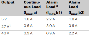
Outputs
– Non-reset:
27V dc @ 2A
5V dc @ 2.2A Rated, 3.0A max
40V dc @ 2.2 Rated, 2.3A max
– Reset: 27V dc @ 2A
+27V: 21-28.8Vdc (typically 27.3V with battery fully
charged)
+40V: 39.5-40.3Vdc
+5V: 4.8-5.25Vdc
Rated Output
Rated output of 5A to supply the panel, fire system
loads and charge 24V battery. De-rate to 4.5A when
used at 120VAC and ambient above 40ºC, e.g. some
T2000 Marine applications.
Maximum Alarm current 5A for 30 minutes
Maximum continuous load current (excluding charging) 2.5A
Rated output power: 136W
The PSU830 cannot support all outputs fully loaded, the
following output load combinations are possible in MX
panel application:
BATTERY CHARGER
A PSU830 may be used to charge 17Ah or 38Ah battery
sets. To meet the requirements of charge to 80% rated
capacity within 24 hours with a 38Ah battery set it is recommended that 2A or greater be allocated for battery
charging. Points to note:
Trickle charge determined by battery capacity, typically
100mA at 27.3Vdc.
Maximum charging voltage 28.8V, battery at -5ºC.
Minimum charging voltage 21V, condition battery discharged.
Deep discharge protection, battery disconnection voltage < 20V.
The PSU830 is not recommended for use with batteries
that have been deep discharged.
Recommended temperature for charging battery -5 to+
40ºC measured in the battery housing with thermistor lead
assembly within 2cms from battery. Sealed lead acid batteries cannot be reliably charged when ambient air temperature around them (the battery ambient) exceeds 50ºC.
Two PSU830 may be connected in parallel (dual PSU configuration) to provide charger output of up to 10A. All other
outputs remain separate, i.e. 2 x 5V, 4 x 27V, 2 x 40V and
must not be connected together. To meet the requirements
of charge to 80% rated capacity within 24 hours with a
65Ah battery set it is recommended that 3.4A or greater
be allocated for battery charging.
BATTERY REQUIREMENTS
17Ah or 38Ah single PSU830.
38Ah dual PSU830. Do not charge 17Ah batteries with
dual PSU830s.
Standby Current Consumption: 90mA @ 24V dc
FAULT MONITORING AND RESPONSE
FAULT CONDITIONS THRESHOLDS
Low AC, < 100VAC.
Battery low <22VDC
Battery disconnect < 20VDC
Battery High Resistance:
– Single PSU: 0.6Ω
– Dual PSU: 0.3Ω
This is the maximum resistance of the battery circuit including battery, wiring and connections to the charger.
Earth (ground fault), operates on the 0V, 5V, 27V and
40V rails. Sensitivity varies with rail with respect to
earth
– 40V and Loop SIG < 300kohm
– 27V < 100 kohm
– 0V and Loop RTN < 22kohm
DESIGN PLANNING
Cables are to be selected in accordance with Publication
17A-02-D and the requirements of local regulations/ code
of practise.
All the terminals at CON3 will accept cable up to 2.5mm2.
To comply with EN54.2 and EN54.4 it is recommend that
the batteries are installed in housing adjacent to the
PSU830 and not further than 2 metres from it. All cabling
between the PSU830 and the batteries housings must be
protected, preferably with metal conduit, in order to provide
adequate mechanical and EMI immunity.
Battery resistance fault monitoring includes the connecting
leads, < 0.1ohm, cabling must be used. The battery temperature thermistor lead assembly may be extended if
required, thermistors must not be swapped between units.
The PSU housing must be positioned so that convection
cooling is unrestricted. For installations where this is not
possible, e.g. installing T2000 fire panel into a console
would require fan cooling of the console and/or large apertures in the T2000 housing to assist cooling of the fire
panel within the console.
If DC units 8800 is exceeded then a second PSU830 is
required this provides power to the second and third
XLM800 and is connected the same way as a PSB800
supplied with PSB800K.
USING PSU830 WITH MX
DESIGNER
Fire panels using modules FIM802 and XLM800 the MX
Digital addressable loop load is defined in MX Designer,
summary below:
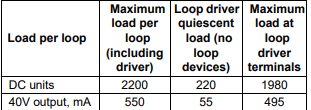
In early versions of MX Designer only PSB800 is available.
When PSB800 is selected it is possible to determine
PSU830 power supply loading as each loop may be loaded
above the DC units Red warning value, provided that the
value does not exceed 2200 DC units per loop and 8800
DC units per PSU830. The voltage drop and AC units Red
warning values stay the same and cannot be ignored. This
means that in many situations a single PSU830 can be
used where previously a combination of PSB800 and
PSB800K were required.
DUAL PSU
In dual PSU configuration only the charger outputs of the
PSU830 are in parallel, all other outputs remain separate,
i.e. 2 x 5V, 4 x 27V, 2X 40V and must not be connected
together. For optimum operational life the panel loading
should be divided equally between the PSU830s wherever
possible (although not essential). MX Designer may be
used to assist in loading of the PSU830.
For dual PSU configuration 0V connection between units
must be made in addition to BT+ and BT-. Cable assembly
must be fitted between CON6 on each unit to provide fault
monitoring. It is necessary to use PTM800 to provide wiring interconnect terminal block from the auxiliary PSU830
to loads such as XLM800.
17Ah battery set must not be connected in dual PSU configuration due to possibility of overcharging.
PRODUCTS REQUIRED FOR
INSTALLATION OF SECOND
PSU830
All items required for installation of second PSU830 are
available using FG number 557.202.044 PSU830K.
PSU830K consists of the following items:
557.202.210 PSU830 Power Supply
557.201.232 PTM800 Power Terminal Module
557.201.231 PSU830 Dual Power Supply Kit
INSTALLATION, GENERAL POINTS
For MX2, ZX4, ZX4BB panels the second (auxiliary)
PSU830 is installed on top of the first (primary)
PSU830.
For MX4000 and MX4000BB, panels the auxiliary
PSU830 is installed in the battery housing. The distance between the housings is constrained by the length
of the interconnecting cables. The recommended
installation is battery housing beneath fire panel.
Connection of primary and auxiliary AC power leads is
via a distribution block supplied with kit 557.201.231.
The external AC supply is connected to a socket which is
mated with distribution block.
If FB800 fuseboard is required it may be mounted on
small chassis plate above the batteries or on top of auxiliary PSU830, if the latter then PTM800 must be
mounted on the side of the PSU830.
The PTM800 should be mounted on the top of the
PSU830 for MX4000 and MX4000BB panels. For
ZX4 and ZX4BB it can either be mounted on top or on
the left hand side with restricted access. For MX2 it
would be sited on the left hand side.
For the ZX4 and ZX4BB panels, nylon cable ties are
required to attach the distribution block to the metal
bracket inside the panel housing.
Monitoring of the auxiliary PSU830 is provided by ribbon cable connected between both power supplies.
Battery capacity must not be less than 38Ah when dual
PSU830 is used as there is possibility of overcharging
with smaller capacity batteries.
CONFIGURATION
HEADERS AND LINKS
The PSU830 has three headers to which are fitted jumper
links, these headers enable selection of the following:
Earth (ground) fault monitoring, there can only be one
Earth fault monitoring circuit active at the fire panel.
Output CON3.2 +27V may be reset (turned off) under
CIE control.
Unit may be configured for single unit or dual unit operation, link selects between primary (master) and auxiliary (slave). There can only be one primary and one auxiliary connected together, no other combinations are
permitted. PSU830 cannot be mixed with any other
PSU.
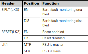
Refer to Table 3, 4 and Figs. 2, 3, 4 for details of terminal
block CON3, header and wiring configurations.
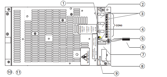
Fig. 2: PSU830 connectors, terminals and links
1 – Battery fuse
2 – Link 3
3 – 27V output fuses
4 – Diagnostic LEDs
5 – Link 4
6 – Battery temperature compensation cable and thermistor
7 – CON6 to CON6 of other PSU830 (dual PSU830 application)
8 – CON1 to FIM 802 PL2 or PTM800 if second PSU830
9 – Link 2
10 –LINK SETTINGS PRIMARY PSU830
LINK 2 (LK2, RESET_ - DIS (disable)
LINK 3 (LK3, E-FLT) - EN (enable)
LINK 4 (LK4) - MTR (master)
11 –LINK SETTINGS AUXILIARY PSU830
LINK 2 (LK2, RESET) - DIS (disable)
LINK 3 (LK3, E-FLT) - DIS (disable)
LINK 4 (LK4) - SLV (slave)
TYPICAL WIRING ARRANGEMENTS OF PSU830
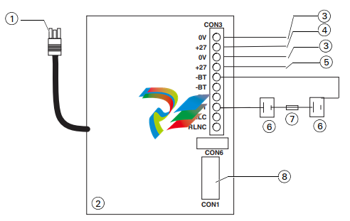
Fig. 3: PSU830 typical wiring of primary power supply
1 – AC power input
2 – Primary PSU830
3 – DC common
4 – +27.3V DC (reset)
5 – +27.3V DC (standard)
6 – 38Ah 12 volt DC batteries
7 – Fuse-lead
8 – To FIM802
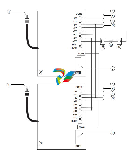
Fig. 4: Wiring for primary and auxiliary PSU830
1 – AC power input
2 – Auxiliary PSU830
3 – Primary PSU830
4 – DC common
5 – +27.3V DC (reset)
6 – +27.3V DC (standard)
7 – To PTM800
8 – To FIM802
9 – 38Ah 12 volt DC batteries
10 –Fuse-lead
OPTIONS
FB800
The fuseboard FB800 provides 8 fused outputs, it is connected to one of the 27V outputs of the PSU830. On the
cover of the PSU830 there are four M3 tapped holes to
accept the male/female threaded pillars supplied with the
FB800.
PTM800
The PTM800 provides screw terminals for 40V, 27V and
5V supplies, necessary when second PSU830 is used to
supply loop power to XLM800s. The 5V, 27V and 40V outputs are not fuse protected. The PTM800 is connected to
the PSU830 via 12 way cable assembly. It is mounted by
four plastic pillars and two 5/8 inch 4/40 UNC screws supplied with the PTM800. The PTM800 may be mounted
on top or on the left hand side of the PSU830.
SERVICE REPLACEMENT
PSU830 is a NOT a form fit replacement for PSB800,
PSM800 or PSB820, refer to publication 120.415.990
for service replacement instructions.
PSU830 should not be used with 10Ah battery sets due to
possibility of overcharging.
ORDERING INFORMATION
PSU830 Power Supply and Battery Charger:
557.202.210
PTM800 Power Terminal Module: 557.201.232
PSU830K Power Expansion Kit: 557.202.044
RELATED DOCUMENTATION
120.415.990 PSU830 Power supply and battery charger
installation and service replacement instructions.
120.415.984 Installation guide - PSU830 Dual Power
Supply kit.
CON1 CONNECTION
Mini blade fuses Farnell RS
2A: 994-3811 219-3536
7.5A: 994-3854 220-0892
-
 HIRSCHMANN MSM20-M2M2M2M2SY9HH9E Ethernet media modul
 -
 HIRSCHMANN SPIDER-PL-20-05T1999999TWVHHHH Industrial Ethernet Rail Switch
 -
 Hirschmann SPIDER-PL-20-07T1M2M299TWVHHHH Industrial ETHERNET Rail Switch
 -
.png) Hirschmann (Belden) RS20-1600M2M2SDAEHC09.1.00 DIN-rail managed industrial Fast Ethernet switch
Hirschmann (Belden) RS20-1600M2M2SDAEHC09.1.00 DIN-rail managed industrial Fast Ethernet switch -
 Hirschmann (Belden) RS30-1602O6O6TDAPHC09.1.00 DIN-rail managed industrial Ethernet switch
 -
 Hirschmann (Belden) RS30-2402O6T1SDAPHH09.0.13 DIN-rail industrial Ethernet switch
 -
Hirschmann (Belden) SPIDER-PL-20-04T1S29999TY9HHHH Ethernet DIN-rail switch
-
 HIRSCHMANN RS20-1600T1T1SDAUHX Switch
 -
 HIRSCHMANN BRS42-0012OOOO-SPCZ99HHSES industrial switch
 -
 Hirschmann RS20-0800S2S2TDHPHH09.0.14 Fast Ethernet DIN rail switch.
 -
 HIRSCHMANN MM20-Z6Z6M2M2SAHH Hybrid Fast Ethernet Media Module
 -
 HIRSCHMANN MM20-Z6Z6T1T1SAHH hot-swappable hybrid Fast Ethernet Media Module
 -
 HIRSCHMANN MM20-P9P9T1T1SAHH Hybrid Fast Ethernet Media Module
 -
 HIRSCHMANN MM20-M4T1T1T1SAHH Hybrid Fast Ethernet Media Module
 -
 HIRSCHMANN MM20-M4M4T1T1SAHH Hybrid Fast Ethernet Media Module
 -
 HIRSCHMANN MM20-M2M2M2M2SZHH Ethernet media module
 -
HIRSCHMANN MM20-M2M2M2M2SAHH Ethernet media module
-
 HIRSCHMANN MM20-T1T1T1T1EBH 4-port Fast Ethernet Copper Cable Media Module
 -
HIRSCHMANN MM20-T1T1T1T1SAHH 4-port Fast Ethernet Copper Cable Media Module
-
HIRSCHMANN MM20-T1T1T1T1SAHH 4-port Fast Ethernet Copper Cable Media Module
-
 HIRSCHMANN MM20-Z6Z6EBH Hot-swappable fast Ethernet media module
 -
 HIRSCHMANN MM20-Z6Z6SAHH Ethernet media module
 -
HIRSCHMANN MM20-Z6Z6Z6Z6EBH Industrial Media Module
-
 MSM40-T1T1T1TZ9HH9E99.9.99 HIRSCHMANN Switch
 -
 HIRSCHMANN MS20-0800SAAEHC / MS20-0800SAAEHC0 8-port modular Layer 2 management Ethernet switch
 -
 Hirschmann RSPM20-4T14T1SZ9HHS9 Switch RSPM20-4T14T1SZ9HHS9
 -
 HIRSCHMANN RS20-1600M2M2SDAEHH09.1. RS20/30/40 Managed Switch configurator
 -
HIRSCHMANN RS20-1600M2M2SDAEHX09.0.00 Ethernet switch
-
 HIRSCHMANN BELDEN SPIDER-PL-20-07T1M2M299TY9HHHH / SPIDERPL2007T1M2M299TY9HHHH
 -
HIRSCHMANN MM3-1FXS2/3TX1 Switching Board Module
-
 HIRSCHMANN RSPE30-24044O7T99-ECCP999HHSE2A08.1.00 Industrial-grade fanless management-type Ethernet switch
 -
 HIRSCHMANN RS30-1602OOZZSDAEHC09.1.00 DIN-rail-mounted managed Layer 2 Ethernet switch
 -
 HIRSCHMANN MACH104-20TX-F Managed 24-port Full Gigabit 19" Switch
 -
 HIRSCHMANN Switch RS20-0800M4M4SDAE
 -
Hirschmann RS30-1602O6O6SDAEHH09.1. Management-type Ethernet switch
-
 Hirschmann RS30-1602OOZZSDAEHC09.0.10 Open rack-style Ethernet switch
 -
 HIRSCHMANN RSPE30-24044O7T99-SCCV999HHSI2SXX.X.XX High-Availability Seamless Redundancy
 -
HIRSCHMANN RSPE30-24044O7T99-SCCZ999HHSE2A DIN-rail Ethernet switch
-
HIRSCHMANN MM2-4TX1-EEC switch
-
HIRSCHMANN MSM40-T1T1T1T1TZ9HH9E99.9.99 Module
-
 HIRSCHMANN RS20 Rail Switch RS20-0400S4T1SDAEHC07.1.01
 -
 HIRSCHMANN M4-FAST8-SFP Fast Ethernet media module
 -
 HIRSCHMANN RS20-0400M2T1SDAP Managed Fast-Ethernet-Switch
 -
 HIRSCHMANN BELDEN SPIDER II 8TX/1FX EEC Industrial Ethernet Rail Switch
 -
HIRSCHMANN MM3-2FXS2/2TX1
-
 HIRSCHMANN RS2-4TX/1FX EEC Industrial Ethernet Rail Switch
 -
 RS30-0802O6O6SDAEHC09.0.10 HIRSCHMANN Switch
 -
 HIRSCHMANN m4-8TP-RJ45 Ethernet Media Module
 -
 HIRSCHMANN MSP30-24040SCZ9URHHE3A switch
 -
 Hirschmann rack MS30-1602SAAPHC
 -
 HIRSCHMANN RS2-FX/FX Industrial Switch Module
 -
Rs1txfx - Hirschmann - Rs1-Tx/Fx Rail Switch
-
RS20-0800S2S2SDAEHC09.1.00 HIRSCHMANN Commutator
-
 Hirschmann EAGLE20 TX/TX Industrial Security Router
 -
 Hirschmann SPIDER-SL-20-04T1S29999SY9HHHH Industrial Switch
 -
 HIRSCHMANN MAR1040-4C4C4C4C9999SMMHRHHXX.X. Gigabit Ethernet Switch configurator
 -
 Hirschmann MAR1040 Industrial Switch
 -
 HIRSCHMANN BELDEN RS30-1602O6O6SDAE
 -
Hirschmann RS20-1600M2M2SDAUHC Ethernet DIN rail switch
-
 HIRSCHMANN OCTOPUS 24M industrial switch
 -
 HIRSCHMANN RS20-1600T1T1SDAE Management-type Ethernet switch
 -
 HIRSCHMANN RS20-1600T1T1SDAUHH industrial switch
 -
HIRSCHMANN RS20-0800M2M2SDAPHC09.0.04 switch
-
 Hirschmann MR 8-03 24V DC Industrial Modular Bridge/Router
 -
 HIRSCHMANN RS20-0400M2T1SDAPHC08.0.01 Managed Switch
 -
 MACH1130 Hirschmann Industrial Switch
 -
 HIRSCHMANN 943824-002 SPIDER 5TX Industrial Ethernet Switch
 -
 HIRSCHMANN RS30-0802O6O6SDAEHC09.1.00 Managed Industrial Switch
 -
 HIRSCHMANN RS20-0400M2M2TDAEHC04.0.01 Industrial Switch
 -
 HIRSCHMANN BRS20-0600Z6Z6-STCZ99HHSES Industrial Switch
 -
 HIRSCHMANN MACH104-20TX-FR-L3P Industrial Ethernet Switch
 -
 HIRSCHMANN RS40-0009CCCCEDBPHH06.0.01 Industrial Switch
 -
 HIRSCHMANN RS2-3TX/2FX EEC Industrial Ethernet Switch
 -
 Hirschmann MACH 1020/1030 Fast/Gigabit Rack Mount Switches
 -
HIRSCHMANN RS20-0800M2M2SDAPHC09.0.14 Industrial Switch
-
 HIRSCHMANN RS20-1600T1T1SDAEHC09.0.04 Industrial Switch
 -
 HIRSCHMANN RSB20-0800T1T1EAABHH Industrial Switch
 -
 HIRSCHMANN MACH4002-48+4G-L3E Industrial Backbone Switch
 -
 HIRSCHMANN RS20-0400S2T1SDAE Industrial Managed Switch
 -
HIRSCHMANN RS20-0800S2T1SDAUHC Industrial Switch
-
 HIRSCHMANN RS20-2400S4S4SDAEHC09.0.14 industrial switch
 -
 HIRSCHMANN OS20-001200T5T5T5- TBBZ999HHNE3S 08.1.00 industrial switch
 -
HIRSCHMANN OS20-001200T5T5T5- TBBZ999HHNE3S 08.1.00 industrial switch
-
 HIRSCHMANN RS40-0009CCCCSDAEHH09.0.14 switch
 -
 Hirschmann RS20-1600T1T1SDAUHC Management-type Ethernet Switch
 -
 Hirschmann M1-8SFP Switche
 -
Hirschmann Industrial Ethernet Ruggedized Switch MACH1000 Family
-
 Basler Electric, Solid State Protective Relay, BE1-60
 -
BASLER ELECTRIC SR4A-2B15B3A Static Voltage Regulator
-
.png) BASLER ELECTRIC EXCITER DIODE MONITOR EDM-200
BASLER ELECTRIC EXCITER DIODE MONITOR EDM-200 -
.png) BASLER ELECTRIC DECS125-15-B2C5 DIGITAL EXCITATION CONTROL SYSTEM V 2.0.9
BASLER ELECTRIC DECS125-15-B2C5 DIGITAL EXCITATION CONTROL SYSTEM V 2.0.9 -
 BASLER ELECTRIC BE1-851 OVERCURRENT PROTECTION RELAY MECHANISM
 -
 Basler Electric BE1-51A / BE151A
 -
 Basler Electric BE1-40Q Loss of Excitation Relay
 -
 Basler Electric BE1-87G Variable Percentage Differential Relay
 -
 Basler Electric BE1-11 Protection System I5A3M2P2N0EA00
 -
 BASLER ELECTRIC DECS-200-1C Digital Excitation Control System
 -
 Basler Electric / Kohler BE1-11g Generator Protection Relay G5A3M2J2N0E000
 -
BASLER ELECTRIC DECS125-15 DIGITAL EXCITATION CONTROL SYSTEM
-
 BASLER ELECTRIC BE1-951 OverCurrent Protecton System
 -
Basler Electric DECS-200-1L Digital Excitation Control System
-
 Basler Electric DGC-2020HD-5NS1DNSBA Digital Genset Controller -
 -
 BASLER ELECTRIC BE1-81T1EE1WA0N1F / BE181T1EE1WA0N1F
 -
 BASLER ELECTRIC BE1-25M1EA6PN5R1F / BE125M1EA6PN5R1F
 -
 BASLER ELECTRIC DECS-250-LN1SN1N DIGITAL EXCITATION CONTROL SYSTEM
 -
Basler Electric DECS-250-CN2CN 1N Digital Excitation Control System Unit
-
 BASLER ELECTRIC DECS-300-C0N0 DIGITAL EXCITATION CONTROL SYSTEM
 -
 BASLER ELECTRIC BE1-87T-A1E-A1J-D0S1F / BE187TA1EA1JD0S1F
 -
BASLER ELECTRIC BE1-11-G6D1M0J2P0E000 Protection System
-
 BASLER ELECTRIC BE1-GPS100-E4N1H1N GENERATOR PROTECTION SYSTEM
 -
 Jaquet Relay card (Auxiliary module) FTV 3090 377Z-03985
 -
 Jaquet Trip Chain Control card FTBU 3034 377Z-05030
 -
 Jaquet with input card -E04 FTFU 3024 -E04 377Z-05855
 -
 Jaquet with input card -E03 FTFU 3024- E03 377Z-03983
 -
 Jaquet FTFU 3024- E02 377Z-03982 with input card -E02
 -
 Jaquet FTFU 3024-E01 377Z-03981 with input card -E01
 -
 Hirschmann RS20-2400T1T1SDAE Industrial Managed Ethernet Switch
 -
 Hirschmann BELDEN EAGLE30-04022O6TT999SCCV9HSE3F
 -
 Hirschmann MM3-2FXS2/2TX MICE Media Module
 -
 Hirschmann RS20-1600M2M2SDAPHC08.0.05 Industrial Managed Switch
 -
 Hirschmann OZD Profi 12M G12-1300 PRO Fieldbus Repeater
 -
Hirschmann SPIDER 4TX/1FX-ST EEC Industrial Ethernet Switch
-
 Hirschmann MM2-2FXM3/2TX1 MICE Media Module
 -
 Hirschmann RS20-2400M2M2SDAPHC09.0.14 Industrial Switch
 -
 Hirschmann RS20-0400M2M2SDAEHC07.1.05 OpenRail Switch
 -
 Hirschmann OZD Profi 12M G12-EEC Fieldbus Repeater
 -
HIRSCHMANN MDA422-1/2-3.5c-23/46 sensor
-
Hirschmann RS30-2402T1T1SDAUHC Managed Industrial Switch


