tycoPSU830 POWER SUPPLY AND BATTERY CHARGER
INTRODUCTION
The PSU830 power supply is intended for use in MX/ZX/
ZXF/T2000/MX2 fire panels. It is a functional replacement for the PSB800, PSM800, PSB820 and PSB821.
The PSU830 provides the following features:
Power factor correction (PFC) to minimise loading
effects on the AC supply and allows operation from 120
- 240V ac.
Temperature compensated, battery charger for sealed
lead acid batteries:
Battery disconnection (load shed) when operating from
battery supply to provide deep discharge protection to
battery set
Fault monitoring includes:-
– battery disconnected, battery wiring short, battery
high resistance, battery voltage low, battery reverse,
temperature compensation fault, ac supply low,
internal charger fault
Common fault output - volt free relay contacts
Diagnostic LEDs for
– AC ok
– Battery fault
– Charger fault
– Ground (earth) fault
Two 27VDC fused field supply outputs with short circuit
protection, one output may be reset (turned off) under
command from fire panel
40VDC 2.2.A output for supplying up to 4 fully loaded
MX Digital loops, typically a single PSU830 may
replace two PSB800 40V 1.2A supplies
5VDC output for use within fire panel/repeater
Selectable Ground (earth) fault monitoring
Battery charging function of two PSU830 may be connected in parallel
TECHNICAL SPECIFICATION
The PSU830 complies with the requirements of:
EN 54-4/1997:A2-2006 Fire Detection and fire alarm
systems; part 4, Power supply equipment
SYSTEM COMPATIBILITY:
Use only with MX/MX2/ZX/ ZXF/T2000 Fire Alarm
Controllers
ENVIRONMENT
Indoor Application only, Land and Marine
Operating Temperature: -10o
to +55oC
Storage Temperature: -20o to +70oC
Operating Humidity: Up to 95% non-condensing
DIMENSIONS (HWD):
62 x 132 x 242mm
EMC
The PSU830 complies with the following:
Product family standard EN50130-4 in respect of Conducted Disturbances, Radiated Immunity, Electrostatic
Discharge, Fast Transients and Slow High Energy
EN 61000-6-3 for Emissions
ELECTRICAL CHARACTERISTICS
Input Voltage: 120-240Vac 50/60Hz (autoranging)
Input Current Rated Load: 0.8-2.2ARMS
Rated input power: 200W maximum
Fig. 1: PSU830 power supply and battery charger
NOTICE
Sealed lead acid batteries cannot be reliably
charged when ambient air temperature
around them (the battery ambient) exceeds
50° C.
Outputs
– Non-reset:
27V dc @ 2A
5V dc @ 2.2A Rated, 3.0A max
40V dc @ 2.2 Rated, 2.3A max
– Reset: 27V dc @ 2A
+27V: 21-28.8Vdc (typically 27.3V with battery fully
charged)
+40V: 39.5-40.3Vdc
+5V: 4.8-5.25Vdc
Rated Output
Rated output of 5A to supply the panel, fire system
loads and charge 24V battery. De-rate to 4.5A when
used at 120VAC and ambient above 40ºC, e.g. some
T2000 Marine applications.
Maximum Alarm current 5A for 30 minutes
Maximum continuous load current (excluding charging) 2.5A
Rated output power: 136W
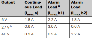
The PSU830 cannot support all outputs fully loaded, the
following output load combinations are possible in MX
panel application:

BATTERY CHARGER
A PSU830 may be used to charge 17Ah or 38Ah battery
sets. To meet the requirements of charge to 80% rated
capacity within 24 hours with a 38Ah battery set it is recommended that 2A or greater be allocated for battery
charging. Points to note:
Trickle charge determined by battery capacity, typically
100mA at 27.3Vdc.
Maximum charging voltage 28.8V, battery at -5ºC.
Minimum charging voltage 21V, condition battery discharged.
Deep discharge protection, battery disconnection voltage < 20V.
The PSU830 is not recommended for use with batteries
that have been deep discharged.
Recommended temperature for charging battery -5 to+
40ºC measured in the battery housing with thermistor lead
assembly within 2cms from battery. Sealed lead acid batteries cannot be reliably charged when ambient air temperature around them (the battery ambient) exceeds 50ºC.
Two PSU830 may be connected in parallel (dual PSU configuration) to provide charger output of up to 10A. All other
outputs remain separate, i.e. 2 x 5V, 4 x 27V, 2 x 40V and
must not be connected together. To meet the requirements
of charge to 80% rated capacity within 24 hours with a
65Ah battery set it is recommended that 3.4A or greater
be allocated for battery charging.
BATTERY REQUIREMENTS
17Ah or 38Ah single PSU830.
38Ah dual PSU830. Do not charge 17Ah batteries with
dual PSU830s.
Standby Current Consumption: 90mA @ 24V dc
FAULT MONITORING AND RESPONSE
FAULT CONDITIONS THRESHOLDS
Low AC, < 100VAC.
Battery low <22VDC
Battery disconnect < 20VDC
Battery High Resistance:
– Single PSU: 0.6Ω
– Dual PSU: 0.3Ω
This is the maximum resistance of the battery circuit including battery, wiring and connections to the charger.


