
parkerFunctional Safety Manual VM600 Machinery Protection Safety Integrated System
PREFACE
About This Manual
This manual provides reference information on using Vibro-Meter’s VM600 Series systems in functional
safety contexts. It is applicable to the following VM600 systems:
• Machinery Protection System (MPS).
Who Should Use This Manual?
The manual is written for the designers and operators of process monitoring and process control systems
using Vibro-Meter’s VM600 Series systems.
The system designers and operators are assumed to have the necessary technical training in safety
engineering, electronics and mechanical engineering (professional certificate/diploma or equivalent) to
enable them to install, program and use the system(s).
Structure of the Manual
This section gives an overview of the structure of the document and the information contained within it.
Some information has been deliberately repeated in different sections of the document to minimize
cross-referencing and to facilitate understanding through reiteration.
The chapters are presented in a logical order. You should read those that are most relevant to you and
then keep the document at hand for future reference.
The structure of the document is as follows:
Chapter 1 Introduction
Explains the purpose and scope of this document.
Chapter 2 Certification
Highlights the VM600 system certification achieved.
Chapter 3 Safety Issues
Provides information on the safety issues related to the use of a VM600
system in a functional safety context.
Chapter 4 Disposal
Provides advice on how to dispose of your electrical and electronic
equipment at the end of its life.
Chapter 5 Customer Support
Provides contact details for technical queries and for getting equipment
repaired. Includes a customer feedback form allowing the user to provide us
with valuable feedback on our documentation.
Symbols and Styles Used in This Manual
The following symbols are used in this manual where appropriate:
NOTE : This is an example of the NOTE paragraph style. This draws the operator’s
attention to additional information or advice relating to the subject.
Important Remarks on Safety
Additional Remarks
Every effort has been made to include specific safety-related procedures in this manual using
the symbols described above. However, operating personnel are expected to follow all
generally accepted safety procedures.
Safety procedures should be communicated to all personnel who are liable to operate the
equipment described in this manual.
Vibro-Meter does not accept any liability for injury or material damage caused by failure to
obey any safety-related instructions or due to any modification, transformation or repair
carried out on the equipment without written permission from Vibro-Meter. Any modification,
transformation or repair carried out on the equipment without written permission from
Vibro-Meter will invalidate any warranty.
The WARNING safety symbol
THIS INTRODUCES DIRECTIVES, PROCEDURES OR PRECAUTIONARY MEASURES WHICH
MUST BE EXECUTED OR FOLLOWED. FAILURE TO OBEY A WARNING CAN RESULT IN
INJURY TO THE OPERATOR OR THIRD PARTIES.
The CAUTION safety symbol
This draws the operator's attention to information, directives or procedures
which must be executed or followed. Failure to obey a caution can result in
damage to equipment.
INTRODUCTION
1.1 Purpose
The purpose of this document is to describe the use of a VM600 machinery protection system
(MPS) in a functional safety context as defined by IEC 61508 and ISO 13849-1.
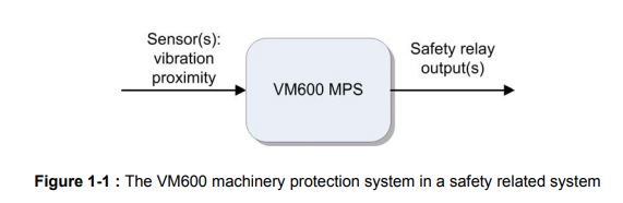
1.2 Scope
The document applies to VM600 series machinery protection systems as outlined below in
Figure 1-1 and Table 1-1
Part Description Mandatory Comment
ABE04x Rack Yes 19” rack
RPS6U Power supply Yes Two PSUs should be used.
The PSUs can be AC or DC.
MPC4 Machinery protection
card (4+2 channels) Yes 1 to n cards
IOC4T Input/output card Yes 1 per MPC4 card
RLC16 Relay expansion card No
MPS1 Software Yes
Warning
The following symbol introduces directives, procedures or precautionary measures which
must be executed or followed.
FAILURE TO OBEY A WARNING MIGHT RESULT IN INJURY TO THE OPERATOR OR THIRD PARTIES AND
DAMAGE TO EQUIPMENT.
1.4 Reference Part Numbers
Part Number Card / Product Name
204-040-100-012 Standard 19” rack
204-040-100-112 Standard 19” rack insulated version
204-040-100-211 Standard 19” rack CSA standard
204-042-100-012 Standard 19” rack Siemens standard
204-042-100-211 Standard 19” rack Siemens CSA standard
200-510-071-113 MPC4
200-560-000-113 IOC4T
200-570-000-111 RLC16
200-582-200-013 RPS6U 24VDC
200-582-300-013 RPS6U 48VDC
200-582-400-011 RPS6U 72VDC
200-582-600-013 RPS6U 110VDC
200-582-500-013 RPS6U 110/230 VAC
209-500-100-022 MPS1 software (used to configure cards)
CERTIFICATION
The VM600 system as described in this document is certified by TÜV® NORD to the following
levels:
• IEC 61508 Safety Integrated Level 1
• ISO 13849-1 performance level C.
A scanned copy of the safety certificate issued by TÜV® NORD is shown on the following
page (see Figure 2-1)
SAFETY ISSUES
3.1 VM600 in a Safety Related System
When a VM600 is part of a safety related system (SRS), certain configuration restrictions
must be applied. In particular:
• The output relays must be configured as de-energized to trip. Specifically:
• the relay is energized when the monitored levels are within their specified tolerances
• the relay is de-energized to indicate an alarm.
• The use of the VM function danger bypass is not allowed.
• The use of the VM function trip multiply is not allowed.
• The alarm must be defined as ‘latching’.
3.2 Valid Safety Configurations
The VM600 machinery protection system (MPS) can be configured in many different
arrangements. These configurations are described in more detail in the hardware manual
(see 1.5 - Applicable Documents). For example, the VM600 can be used to protect rotating
machines in a safety related system.
Monitored Signal Valid for SRS Reference in HW
Manual
Broad-Band Absolute Bearing Vibration Yes Section 7.1
Tracking No Section 7.2
Relative Shaft Vibration with Gap Monitoring Yes Section 7.3
Absolute Shaft Vibration Yes Section 7.4
Shaft Position Yes Section 7.5
Safety Inputs and Outputs
Monitored Signal Valid for SRS Reference in HW
Manual
Broad-Band Absolute Bearing Vibration Yes Section 7.1
Tracking No Section 7.2
Relative Shaft Vibration with Gap Monitoring Yes Section 7.3
Absolute Shaft Vibration Yes Section 7.4
Shaft Position Yes Section 7.5
Table 3-1 : Overview of valid safety configurations
Signal Comments Reference in HW
Manual
MPC4 CH1-CH4 (inputs) Ensure cabling follows the
guidelines Table 9-1 part 1
MPC4 relay contacts (outputs) Table 9-1 part 2
Safety Function
With reference to IEC 61508 the safety function for the system is defined below.
For the required safety function SF1, the following safety parameters (SP) are required in
accordance with IEC 61508.
SF
Number Description Safe State
Required
Safety
Parameters
SF1
If an input value (or values)
exceed(s) a predefined limit,
then a trip activation signal is
made.
De-energize to trip (open relay
contact).
That is, the EUC and the
VM600 interpret a
de-energized state as a safe
state.
See table
below
SP
Number Safety Parameter Requirement Comment
SP1 Safety integrity level SIL 1
SP2 Operational mode Low demand mode
SP3a Component type sensor Type B
Component type logic
(measuring logic) Type B
Component type
actuator (relay) Type A
SP4 Hardware fault tolerance
(HFT) 0
Single channel architecture
of an already existing
proven-in-use system
should be used for SIL 1
application without any
changes
SP5 Probability of failure on
demand (PFD) ≥ 10-2 to 10-1
PFD by proof test years
FMEDA
0.5 1.0 2.0 5.0
5.5e-3 1.1e-3 2.2e-2 5.0e-2
SP6
Safe failure fraction
(SFF) for Type A
subsystem
< 60% for SIL 1 and
HFT 0
Safe failure fraction
(SFF) for Type B
subsystem
60% to < 90% for SIL 1
and HFT 0
In practice, the output relay or relays are normally the ‘input’ to a safety related PLC that takes
this input together with other safety related signals.
3.5 ISO 13849-1 Performance Level
The table below shows the breakdown of performance level (PL) by diagnostic coverage and
mean time to dangerous failure (MTTFd).
Safety Time
After the defined safety level threshold has been exceeded, the VM600 system will open the
associated safety relay within 100 ms.
3.7 Protection of Relay Contacts
In a safety system it is important to protect against a relay contact becoming welded due to
excessive current being inadvertently passed. Therefore, the outputs must be protected by a
5A(T) fuse
nstallation
The system shall be installed following the procedures described in the MPS Hardware
Manual (Standard Version) MAMPS-HW/E (see 1.5 - Applicable Documents). Environmental
restrictions are described in Appendix A of the manual.
3.9 Configuring the System
It is important that the levels (vibration and so on) are adjusted to suit the system under
protection and that a manual verification is made of the parameters that are uploaded to the
system (MPC4 card).
Note that the procedures described should only be performed by competent and authorized
personnel following the plant specific guidelines in force at the installation site.
3.9.1 Define the levels
The choice of alarm levels must be made in consultation with the site manager. It is the end
user’s responsibility to ensure that the alarm levels are appropriate for the particular system
being protected.
The levels are defined using the MPS1 software (supplied) or the MPS2 software (optional).
Please refer to the appropriate documentation for complete information.
3.9.2 Define the alarm outputs
Any relay on the MPC4 or RLC16 cards can be configured to provide the safety function. As
previously noted, the alarms must be:
• configured as ‘latching’
• de-energized to ‘trip’.
3.9.3 Upload the levels and configuration
Once the system parameters have been correctly defined using the MPS software, the
configuration for each MPC4 card must be uploaded to the card. This procedure is described
in the MPS1 Software Manual MAMPS1-SW/E (see 1.5 - Applicable Documents).
3.9.4 Configuration verification
Whilst the actual upload of data is controlled by CRC verification and other techniques, in
order to fulfil the IEC 61508 requirements a manual verification of this upload is required. The
verification is made by downloading the configuration from the MPC4 card to the computer
and comparing the data received with the original data uploaded to the card.
This procedure is described below.
• Select the appropriate MPC4 card on the MPS software (as used in 3.9.3 - Upload the
levels and configuration).
Use the Dump to File option to save the configuration as pc_card_1.csv.
• Define a dummy rack using a Tag name from_sys_1.
• Select this rack, connect to the MPC4 card concerned and read its configuration back to
the computer.
• Dump this file as sys_card_1.csv.
• Using the MS-DOS fc (file compare) command, compare the two files. The only
difference should be the download time as shown in Figure 3-1.
3.10 Commissioning
The system should be commissioned as an integral part of the overall SIS commissioning.
INSTALLATION AND COMMISSIONING SHOULD ONLY BE PERFORMED BY COMPETENT AND
AUTHORIZED PERSONNEL FOLLOWING THE PLANT SPECIFIC GUIDELINES IN FORCE AT THE
INSTALLATION.
3.10.1 Guidelines for commissioning
Installing a VM 600 system is fully described in section 8 of the MPS Hardware Manual
(Standard Version) MAMPS-HW/E.
Offline Proof Test
When the VM600 is taken offline, the attached system and equipment are no longer
protected. Therefore, this procedure should only be undertaken by authorized personnel
respecting the overall plant operations procedures. There should be no need to remove the
equipment from site to perform these tests unless it is considered more convenient.
The offline proof test reveals any dangerous faults that might not be detected in normal
operation.
For a VM600 system the proof test must be performed every 5 years or less.
3.12 Repair and Maintenance
If the VM600 system is under maintenance or repair, then the attached system and
equipment may no longer be protected. Therefore, this procedure should only be undertaken
by authorized personnel respecting the overall plant operations procedures.
3.12.1 Guidelines for the proof test
3.12.1.1 Reset
1- Reset the system by performing a cold start. That is, turn off and then turn on the rack.
2- Verify the safety relay status by performing a continuity test.
3- Observe the diagnostic LEDs and note any abnormalities. Refer to the MPS hardware
manual for further information.
3.12.1.2 Threshold tests
These tests are essentially a sub-set of the site commissioning plan. As such, they will vary
widely depending on the number of channels configured, the sensor type, and so on.
The levels used have to be determined for each particular installation. An example for one
channel of a vibration alarm is given below.
1- Disconnect the IOC4T from the sensor cables.
2- Simulate an N1 vibration signal at a site specific frequency for 100% RPM.
3- Inject a signal at (0.8 x alarm level) and verify that the system does not trip.
4- Inject a signal at (1.2 x alarm level) and verify that the system does trip.
3.12.1.3 Maintenance
System maintenance should be performed following the guidelines in the MPS Hardware
Manual (Standard Version) MAMPS-HW/E (see 1.5 - Applicable Documents). When the
VM600 is taken offline, the attached system and equipment are no longer protected.
Therefore, maintenance should only be undertaken by authorized personnel respecting the
overall plant operations procedures.
DISPOSAL
If it is decided to scrap a VM600 system, then it must be disposed of in an environmentally
friendly manner. In European Community countries, the Waste Electrical and Electronic
Equipment (WEEE) directive is applicable.
• According to the WEEE Directive 2002/96/EC, all waste electrical and electronic
equipment should be collected separately and then treated and disposed of in
accordance with the best available and environmentally friendly techniques. Waste
electrical and electronic equipment may contain substances hazardous to the
environment (and to humans) but it is also a valuable resource of new raw materials.
Therefore, it is important to collect electrical and electronic waste separately from other
waste.
CUSTOMER SUPPORT
5.1 Contacting Us
Vibro-Meter’s worldwide customer support network offers a range of support including 5.2 -
Technical Support and 5.3 - Sales and Repairs Support. For customer support, please
contact your local Vibro-Meter representative. Alternatively, contact our main office:
Customer support
Vibro-Meter SA
Route de Moncor 4
PO Box 1616
CH-1701 Fribourg
Switzerland
Telephone: +41 (0)26 407 11 11
E-mail: energysupport@ch.meggitt.com
Web: www.vibro-meter.com
Vibro-Meter SA is an operating company of Meggitt PLC.
5.2 Technical Support
Vibro-Meter’s technical support team provide both pre-sales and post-sales technical
support, including:
1- General advice
2- Technical advice
3- Troubleshooting
4- Site visits.
NOTE : For further information, please contact Vibro-Meter (see 5.1 - Contacting Us).
5.3 Sales and Repairs Support
Vibro-Meter’s sales team provide both pre-sales and post-sales support, including advice on:
1- New products
2- Spare parts
3- Repairs.
Customer Feedback
As part of our continuing commitment to improving customer service, we warmly welcome
your opinions. To provide feedback, please complete the Customer Feedback Form on page
5-5 and return it Vibro-Meter’s main office (see 5.1 - Contacting Us).
-
 Jaquet Relay card (Auxiliary module) FTV 3090 377Z-03985
 -
 Jaquet Trip Chain Control card FTBU 3034 377Z-05030
 -
 Jaquet with input card -E04 FTFU 3024 -E04 377Z-05855
 -
 Jaquet with input card -E03 FTFU 3024- E03 377Z-03983
 -
 Jaquet FTFU 3024- E02 377Z-03982 with input card -E02
 -
 Jaquet FTFU 3024-E01 377Z-03981 with input card -E01
 -
 Hirschmann RS20-2400T1T1SDAE Industrial Managed Ethernet Switch
 -
 Hirschmann BELDEN EAGLE30-04022O6TT999SCCV9HSE3F
 -
 Hirschmann MM3-2FXS2/2TX MICE Media Module
 -
 Hirschmann RS20-1600M2M2SDAPHC08.0.05 Industrial Managed Switch
 -
 Hirschmann OZD Profi 12M G12-1300 PRO Fieldbus Repeater
 -
 Hirschmann SPIDER 4TX/1FX-ST EEC Industrial Ethernet Switch
 -
 Hirschmann MM2-2FXM3/2TX1 MICE Media Module
 -
 Hirschmann RS20-2400M2M2SDAPHC09.0.14 Industrial Switch
 -
 Hirschmann RS20-0400M2M2SDAEHC07.1.05 OpenRail Switch
 -
 Hirschmann OZD Profi 12M G12-EEC Fieldbus Repeater
 -
 HIRSCHMANN MDA422-1/2-3.5c-23/46 sensor
 -
Hirschmann RS30-2402T1T1SDAUHC Managed Industrial Switch
-
 Hirschmann OZD GENIUS G12 Industrial Switche
 -
 Hirschmann OZD 485 G12-1300 PRO Fieldbus Repeater
 -
 Hirschmann MM2-2FXM2 MICE Media Module
 -
 Hirschmann RS20-1600S2T1SDAUHC Managed Industrial Switch
 -
 Hirschmann MS20-0800SAAEHH04.2.04 MICE Switch
 -
 Hirschmann SPIDER 4TX/1FX EEC Unmanaged Industrial Switch
 -
 HIRSCHMANN MS4128-L3P EEC Managed Industrial Ethernet Switch
 -
 HIRSCHMANN RS20-0400M2T1SDAPHC08.0.01 Managed Switch
 -
 ETEL EA-S0M-400-40/80A-0000-00 AccurET Modular Power Supply
 -
 ETEL EA-B0I-0-0-0000-00 Backplane Interface Board
 -
 ETEL EA-P2M-400-15/40A-0100-00 Position Controller
 -
ETEL EA-P2M-400-15/40A-0000-00 Position Controller
-
 ETEL EA-P2M-400-10/20A-0100-01 Position Controller
 -
 ETEL EA-P2M-400-10/20A-0000-01 Position Controller
 -
 ETEL EA-P2M-400-5/10A-0100-01 Position Controller
 -
 ETEL EA-P2M-048-2.5/5A-0000-01 Modular Position Controller
 -
 ETEL EA-S0M-300-40/80A-0000-00 Power Supply Module
 -
 ETEL EA-P2M-300-07/15A-0100-01 Position Controller
 -
 ETEL EA-P2M-300-07/15A-0000-01: Modular Position Controller
 -
 ETEL EA-P2M-300-4/7.5A-0100-01 Overview
 -
 Basler Electric MOC2. Motor Operated Potentiometer
 -
 Basler Electric BE1-11 RTD Module, Resistance Temperature Detector
 -
 Basler Electric RDP-110C, Remote Display Panel
 -
 Basler Electric VRM-2020. Voltage Regulation Module
 -
 Basler Electric IDP-1500. Interactive Display Panel
 -
 Basler Electric AEM-2020. Analog Expansion Module
 -
 Basler Electric IDP-2020. Interactive Display Panel
 -
 Basler Electric CEM-2020. Contact Expansion Module
 -
 Basler Electric CEM-125. Contact Expansion Module
 -
 Basler Electric BE2000E, Digital Voltage Regulator
 -
 Basler Electric SMC-150. Synchronous Motor Controller
 -
 Basler Electric AVC125-10. Voltage Regulator
 -
 Basler Electric BE1-25. Sync-Check Relay
 -
 Basler Electric DGC-2020ES, Digital Genset Controller
 -
 ETEL EA-P2M-400-5/10A-0000-01 Position Controller
 -
 Basler Electric BE1-64F, Ground Fault Relay
 -
 Basler Electric BE1-79M, Multi Shot Reclosing Relay
 -
 Basler Electric BE1-81O/U, Digital Frequency Relay
 -
 Basler Electric BE1-87B, High Impedance Bus Differential Relay
 -
 Basler Electric BE1-79A, Reclosing Relay
 -
 Basler Electric BE1-27. BE1-59. BE1-27/59. Voltage Relay
 -
 Basler Electric SMC-250. Synchronous Motor Controller
 -
 Basler Electric SGC-250N, Synchronous Generator Controller
 -
 Basler Electric SGC-250. Synchronous Generator Controller
 -
 Basler Electric BE1-50/51 Plug and Play and Retrofit Relays
 -
 Basler Electric DECS-2100. Digital Excitation Control System
 -
 Basler Electric DECS-250E, Digital Excitation Control System
 -
 Basler Electric BE1-700V, Voltage Only Digital Protective Relay
 -
 Basler Electric DECS-250. Digital Excitation Control System
 -
 Basler Electric DECS-450. Digital Excitation Control System
 -
 Basler Electric DECS-150. Digital Excitation Control System
 -
 Basler Electric ES-49. Temperature Relay
 -
 Basler Electric ES-81O/U, ES-81O,ES-81U Overfrequency Relay
 -
Basler Electric ES-74V, DC Voltage Sensing Relay
-
Basler Electric ES-27/59. Under/Overvoltage Relay
-
 Basler Electric ES-27. Undervoltage Relay
 -
 Basler Electric ES-25. Sync-Check Relay
 -
 Basler Electric ES-47, ES-47N Phase Sequence Relay
 -
Basler Electric ES-37.ES-37/51 Undercurrent Relay
-
 Basler Electric ES-32. Reverse Power Relay
 -
Basler Electric ES-59. Overvoltage Relay
-
 Basler Electric ES-55. Power Factor Relay
 -
 Basler Electric DGC-2020HD, Digital Genset Controller
 -
 Basler Electric BE1-FLEX, Protection, Automation, and Control System
 -
 Schneider GUTOR OC0935 Power Factor Sampling Board
 -
 Schneider GUTOR OC0922 Analog Signal Isolation Board
 -
 Schneider GUTOR OC0908 Battery Voltage Detection Board
 -
Schneider GUTOR OC0947 Temperature / IGBT Sampling Board
-
 Schneider GUTOR OP2601 Communication Expansion Board
 -
 Schneider Electric GUTOR OP2312 bypass control board
 -
 Schneider Electric GUTOR OP2130 Cooling Fan Monitoring & Control Board
 -
 Schneider Electric GUTOR OP2010 Battery Test Board / Battery Management Diagnostic Card
 -
Schneider Electric GUTOR OP2552 Three-phase Power Connection Board Assembly
-
 Schneider Electric GUTOR OP1922A Parallel Control Board / Load-Sharing Synchronization Module
 -
 Schneider Electric GUTOR OP6290B Inverter Feedback Acquisition Board / Signal Scaling Module
 -
Schneider GUTOR OP6280 Basic Signal Board
-
Schneider Electric GUTOR OP2456 / OP2456B Main control board
-
 Schneider Electric GUTOR OP2452 Power Plug-in Panel
 -
 Schneider Electric GUTOR OP2450 Parallel Communication Board
 -
Schneider Electric GUTOR OP2406 Interface Fuse Monitoring Board
-
 Schneider Electric GUTOR OC0919 High-Power Semiconductor Module
 -
 Schneider Electric GUTOR OP6281A System Logic Interface Board
 -
 Schneider Electric GUTOR OP6285A Power Signal Acquisition Board
 -
 Schneider Electric GUTOR OP2438 Fan Monitor & Drive Protection Board
 -
Schneider Electric GUTOR OP2446 Main Control CPU Board
-
 ROLLS-ROYCE CE05-00 Steering Gear Control Module
 -
 ROLLS-ROYCE MARINE AS-BRATTVAAG WRC1021A CONTROLLER CARD
 -
ROLLS ROYCE DECK MACHINERY MPC-300-A7029099 TERMINAL CONTROLLER UNIT
-
 ROLLS-ROYCE HELICON THRUSTER CONTROL PANEL LF90S-01-06
 -
 Rolls-Royce PCC1030C Panel Controller Card
 -
 Rolls-Royce RRDIO15 Remote Digital Input/Output Module
 -
 Rolls-Royce TDI-11 Pitch & Direction Indicator Module
 -
 Rolls-Royce CCN 01 CANman Controller Network Module
 -
 Rolls-Royce SLIO 01 CANman Controller Network Module
 -
 Rolls-Royce MPC-210 Winch & Propulsion Control Module
 -
Rolls-Royce MTI-144 Engine Control Module
-
 Rolls-Royce Tenfjord FB10-002 Steering Gear Module (E-4500-40-1)
 -
 ROLLS ROYCE MARINE AS CIRCUIT BOARD (PCB) RRAI016
 -
 Rolls-Royce Marine AS PIP6-1 Marine Controller
 -
 ROLLS-ROYCE MPC-300 STARTER CONTROL UNIT A7029099
 -
 Rolls-Royce Data Respons MPCF1-10.4" Maritime Panel Computer
 -
 ROLLS-ROYCE MARINE OLC-40009 PCB CARD
 -
Rolls-Royce Marine Brattvaag WRC1021B Controller Board
-
 ROLLS-ROYCE CCN 01 & ROLLS-ROYCE SLIO 02 CANMAN CONTROLLER NETWORK
 -
.png) ROLLS-ROYCE ATC-3-A7033172 AQUAMASTER TURNING CONTROLLER
ROLLS-ROYCE ATC-3-A7033172 AQUAMASTER TURNING CONTROLLER -
 ROLLS-ROYCE POSCON V.3 JOYSTICK MODULE 6459
 -
.png) Rolls-Royce Marine 389-496-00 Joystick Remote Control Panel 6799-W, 389-996-00
Rolls-Royce Marine 389-496-00 Joystick Remote Control Panel 6799-W, 389-996-00 -
 Rolls-Royce data respons 10.4'' Panel Computer 98H010A0000I/R10I53S
 -
 Rolls-Royce H1127.0101 Marine Controller 000068308
 -
 Rolls-Royce CU40-0106-50 Steering Gear Control Panel


