
METSOmaxPAC Hardware Reference Guide
maxPAC
Input/Output Subsystem
Overview
The maxPAC Input/Output System links the maxDNA Distributed Control
System to real world process control inputs and outputs. The Input/Output
system uses a compact design to provide the system with greatly enhanced
I/O capacity in relatively little space. A close relationship exists, in turn,
between this I/O system and the maxDNA Distributed Processing Unit
(DPU) which it serves.
The DPU and the I/O modules mount in an I/O chassis assembly. The
backplane in the chassis assembly provides the I/O bus connection between
the DPU and the I/O modules. It also provides the system power and field
power connections to the modules. Multiple I/O chassis that share the I/O bus
can be installed in a cabinet.
Model IOP I/O Subsystem
Cabinet
Two standard cabinet types are available for the mounting of I/O system
hardware. The cabinet is available as either a NEMA (National Electrical
Manufacturers Association) type 1 or 12 and consists of the following:
Welded steel construction
Front and Rear access
I/O mounted in front and rear of cabinet (standard)
I/O mounted in front and terminations in rear of cabinet (option)
Other mounting arrangement options are also available
Removable doors
19” rack mount rails with standard E.I.A. hole spacing
Top or bottom Cable access
Size 85 7/8” h x 24 ¾”w x 38 7/8”d
Optional Cabinet styles and sizes are also available.
The following figure shows a typical cabinet arrangement with I/O in both
the front and rear of the cabinet.

Figure 1-1. Typical Cabinet Arrangement, Front and Rear Views
Chassis Assembly
Three chassis assembly types are available for the installation of the I/O
module as follows:
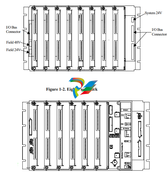
IOP382 Eight-pack assembly to accommodate up to eight maxPAC I/O
modules. The DPU4F can also reside in this chassis.
IOP383 Six-pack assembly to accommodate a DPU4E or a Model 564 I/O
module in the right most position along with six maxPAC I/O modules; the
DPU4E takes up the equivalent of two maxPAC I/O module positions.
IOP381 Four-pack assembly to accommodate four maxPAC or Model 564
I/O modules.
The rack assemblies contain an I/O backplane featuring edge connectors for
I/O modules and connectors for 24V system supply and 24V and 48V loop
power supplies. Input/Output modules connect to the I/O bus through four to
eight connectors on the backplane, depending on chassis style.
The backplane also contains ribbon cable connectors to interconnect chassis
assemblies and extend the I/O bus to the maximum number of modules
supported by the DPU.
DPU Mounting
DPU4E mounts in the right most position of the six-pack chassis assembly. It
occupies the equivalent of two I/O modules. Refer to Publication 278590 for
DPU4E information. DPU4F mounts in the left most position of the eightpack chassis assembly. It occupies the equivalent of one I/O module. Refer to
Publication 278705 for DPU4F information.
I/O Modules
The I/O modules are rugged enclosed printed circuit board assemblies. The
edge connection at the rear of each module provides the interface to the
backplane and the I/O bus. System power and field power, when applicable, is
also available through this connection.
While I/O modules vary by type, they may include one or more of the
following:
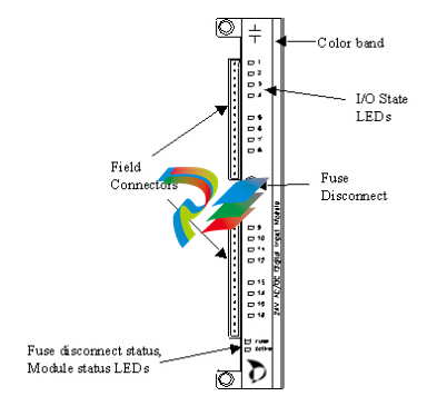
A color bar on the module faceplate identifies the module type. Each
module type has a unique color.
Euro-style terminal connector blocks for field wiring; each block contains
16 connectors;
Rotary address switch;
Light Emitting Diodes (LED) for module status indication;
All the modules that require field power include a front mounted fuse
disconnect and a LED fuse status indication;
All discrete modules include front mounted LEDs for input/output logic
state;
The TC module includes front-end connectors with thermistors to measure
the junction temperature for cold junction compensation.
The I/O modules may be inserted and withdrawn safely with 24 Vdc and field
power applied.
I/O Module Types
Because of the variety of input and output ranges needed in distributed control
applications, the Model IOP I/O offers many types of easily configurable
discrete and analog I/O modules. For a list of modules, along with their
ranges and number of points per module, refer to the following tables.
Digital Input (AC/DC)*
Part Number Description
IOP330 24 Vdc common input; 16 channels
IOP334 24 Vdc isolated input; 16 channels
IOP331 48 Vdc common input; 16 channels
IOP332 120 Vac/dc isolated input; 16 channels
IOP333 240 Vac/Vdc isolated input; 16 channels
IOP350 Form C relay; 10 channels
IOP351 Form A/B relay; 16 channels
IOP335 Pulse I/O , 8 channels
*ac Voltages/currents are RMS
The maxDNA Input/Output System uses the Model APS Power Supply
Assembly, which provides 24V dc power for Distributed Processing Units
and I/O. This Power Supply Assembly consists of a 19-inch rack mount or
flush mount chassis accommodating up to six independent 10 amp power
supply modules. Metso Automation typically installs the power supply
modules in an N + 1 redundancy configuration. Because each module is
individually isolated, the chassis can be split to provide both system power
and loop power.
Power supply features consists of the following:
Redundant AC power inputs
250 Watt power supply modules
Hot replaceable
Current Sharing
Power factor correction
Front panel indicators on each module
AC input
Output voltage status
Output current level
External status signals
Field Termination Options
A maxPAC system uses three field cable termination approaches:
Local Terminations Field cables terminate directly on the I/O
module.
Remote Terminations Field cables terminate on terminal blocks
remotely to the I/O module with an
interconnecting cable back to the I/O module.
Termination Assemblies The QuadPAT, Turbine Valve and Overspeed
modules require a DIN rail mounted termination
assembly. Field cables terminate on this
assembly with an interconnecting cable back to
the I/O module.
Local Terminations (standard)
Each I/O module is supplied with two 16 point, “Euro-Style” screw clamp
plugs that mate to the Printed Circuit Board Header on the module. Field
cables would be routed directly to these Euro-Style plugs, which can accept
up to a #12awg conductor.
Remote Terminations (option)
Many remote field cable termination options are possible. Listed below are a
few examples:
I/O in front of cabinet, terminations in the rear of cabinet.
Termination cabinet mounted adjacent to I/O cabinet.
Termination cabinet located remotely from I/O cabinet.
The types of terminal blocks installed in the termination facility are too
numerous to list; typically these terminations are DIN rail style. The cabling
back to the I/O module is typically made using two multi-conductor cables,
one to each of the Euro-Style plugs supplied with the individual I/O module.
Termination Assemblies
Part Number Description
IOP337 QuadPAT Termination Assembly
IOP342 Turbine Valve Termination Assembly
IOP346 Turbine Overspeed
CTO301 QuadPAT Module to Termination Assembly Cable
CTO302 Turbine Valve Module to Termination Assembly Cable
CTO303 Turbine Overspeed Module to Termination Assembly
Cable
Installing Model IOP I/O Equipment
This section covers the physical mounting and installation of the Model IOP
I/O equipment. See "Module Mounting Considerations," before mounting
any equipment.
The following tools and hardware are required:
Screwdriver
Hex Key Wrench, Metso Part No. 064598
Mounting Screws, Metso Part No. 030162 (8 per unit supplied)
Nut Retainers, Metso Part No. 003530 (8 per unit supplied)
Crimp Tool for field connectors, Weidmuller Part No. 906480
Crimp Contact Removal Tool, Weidmuller Part No. 906481
Before mounting any hardware, see "Cabling, Power, and Ground Wiring."
Sequence of Mounting Operations
Mounting the parts of the Model IOP I/O in proper order can save time and
duplication of effort.
Follow this sequence as closely as possible for best results:
1. Refer to field wiring instructions that can influence mounting locations
for chassis assemblies and chassis assembly/module replacement.
2. Mount the chassis assemblies; see "Mounting I/O Chassis Assemblies."
3. Perform all steps as outlined in "Cabling, Power, and Ground Wiring."
5. Complete field wiring.
6. Refer to "Module Addressing" for switch settings and jumper selections.
7. Install I/O modules.
If your field wiring enters through the bottom of the cabinet, mount the
Model IOP I/O units from top to bottom. This will make wiring of future
units easier, since you will not have to pull wires from the bottom of the
cabinet past existing Model IOP I/O units. This same reasoning applies to
field wiring entering the top of the cabinet. Here you mount the Model IOP
units from bottom to top.
Mounting I/O Chassis Assemblies
The Model IOP I/O chassis assembly attaches to the rear mounting rails in
standard 19-inch maxDNA I/O cabinets. Three chassis styles are available.
See “Chassis Assembly.” Up to seven chassis assemblies may be installed in
a standard cabinets.
Usually, the Model IOP I/O units are supplied already mounted in cabinets,
but if you are mounting them yourself, follow this procedure.
Note: before you mount an I/O chassis, it should contain the I/O backplane.
To attach the chassis assembly:
1. At the desired chassis assembly mounting location in the cabinet, place
eight 10-32 nut retainers (Metso Part No. 003530) in the rear mounting
rail holes that correspond to the eight screw slots on the Model IOP
chassis assembly.
2. The holes in the maxDNA cabinet rear mounting rails are arranged in a
repeating pattern of two holes close together separated by a single hole.
To make sure all chassis assembly mounting screw cutouts line up to
corresponding mounting rail holes, you must align the top mounting
screw cutouts (left and right) of the chassis assembly with the top holes
(left and right) of two hole pair.
3. Position the chassis assembly (two ribbon connectors to the right) so that
the screw slots align with the nut retainers. Insert eight 10-32 mounting
screws (Metso Part No. 030162) and tighten securely.
Cabling, power wiring, and chassis assembly to cabinet frame grounding
should be completed before mounting the I/O modules. See next section.
Cabling, Power, and Ground Wiring
This section describes power wiring, Model IOP I/O connection, and
connection to other Model IOP I/O units. The connections covered in this
section should be done after the chassis assemblies are in place and before
the I/O modules are mounted. Some cabling can be done when the I/O
modules are mounted, but the job is easier when they are removed. (See also
Interconnecting I/O Racks).
Cables used in the maxDNA Distributed Control Systems are labeled at both
ends with the device and connector number. Interconnecting ribbon cables
are designed for specific orientation, however, the connectors still prohibit
wrong electrical connection.
Refer to Publication 278561, System Power and Grounding, for a discussion
of cabinet grounding.
Supplying 24V Power to the I/O Modules
The I/O system requires a 24 Vdc ±4.0 Vdc power supply. Normally, this is a
maxDNA power supply mounted in the cabinet holding the DPU; to ensure
reliability, Metso Automation recommends using a maxDNA power supply
exclusively. If another 24 Vdc power supply is used, it must meet the same
specification requirements as the maxDNA supply. All modules are
individually fused. The CMOS technology in the Model IOP I/O design
results in low module power consumption.
Whether the power source is the standard maxDNA supply or another
supply, the +24 Volts connector plugs into the 24V connector on the right
side of the I/O backplane.
Caution: The +24 Vdc power supply used to power any maxDNA hardware
should never be used for external relay contact wetting or to power any other
field equipment. Use a separate supply for contact wetting to provide noise
and interference protection for the maxDNA hardware.
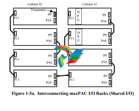
Interconnecting I/O Racks
Use a ribbon cable to interconnect, in a daisy chain manner, two or more
adjacent I/O chassis assemblies in the same maxDNA I/O cabinet group. The
cables should be installed in a manner that minimizes the total I/O bus length.
This is done by utilizing the I/O bus connectors on both ends of the racks so
that the bus “flows through” the racks.
For example, consider the two-cabinet system shown in Figure 1-5a. A
maxDPU4F pair is installed in the leftmost slots of the top two racks in
cabinet 1. The bus begins at the DPU and flows through the rack to the
connectors on the right side of the rack (P9 & P10). A ribbon cable connects
the right side of rack 1 to the right side of rack 2. The bus flows through
rack 2 to connector P11. Another ribbon cable connects the left side of rack
2 to the left side of rack 3. The bus flows through rack 3 to connectors P9
and P10. This same pattern is repeated until the last rack has been reached.
Notice that the bottom rack of cabinet #1 is connected to the bottom rack of
cabinet #2 by a cable that runs from P11 to P9. This is because that results in
a shorter cable length than it would be had it run from P11 to P11. It is also a
much shorter cable length than if it had been run from the bottom of cabinet
1 to the top rack in cabinet 2.
To reiterate, when cabling the I/O racks together, the goal is to keep the I/O
bus length as short as possible. Connecting the cables on alternate sides of
the racks so that the I/O bus “flows through” from one rack to the next does
this.
Note that the ribbon cable connectors are keyed. The color stripe on the
ribbon cable should match pin 1 on the backpanel connector. Connector pin
1 is indicated by a white triangle symbol on the backpanel adjacent to the
connector.
A bus terminator (CPO402) must be installed at the end of the I/O bus
farthest from the DPU. The bus terminator is a small PC card assembly that
is designed to plug in to the I/O bus connector. When installing a terminator,
be sure to match its pin 1 indication to the pin 1 indication on the backpanel.
In Figure 1-5a, the terminator is shown inserted into connector P9 of the top
rack in cabinet 2. That is the point on the bus that is farthest from the DPU.
If you add I/O racks to your system at a later date, remember to move the
terminator from its old location to the new end of the bus.
I/O Bus Terminators are not used to provide impedance matching. They are
simply pull-up resistors that are used to improve the rise time of the open
collector I/O bus signals. For that reason, in some instances (e.g., a system
with both maxPAC and 564-style I/O connected with long cable runs), an
additional terminator at the DPU end might be required. Monitor the I/O Bus
Errors and, if your system seems to have an excessive amount, try adding the
additional terminator.
Refer to the Bus Extender Module chapter in this manual for information on
how to install terminators when BEMs are present in the system
-
 HIRSCHMANN MSM20-M2M2M2M2SY9HH9E Ethernet media modul
 -
 HIRSCHMANN SPIDER-PL-20-05T1999999TWVHHHH Industrial Ethernet Rail Switch
 -
 Hirschmann SPIDER-PL-20-07T1M2M299TWVHHHH Industrial ETHERNET Rail Switch
 -
.png) Hirschmann (Belden) RS20-1600M2M2SDAEHC09.1.00 DIN-rail managed industrial Fast Ethernet switch
Hirschmann (Belden) RS20-1600M2M2SDAEHC09.1.00 DIN-rail managed industrial Fast Ethernet switch -
 Hirschmann (Belden) RS30-1602O6O6TDAPHC09.1.00 DIN-rail managed industrial Ethernet switch
 -
 Hirschmann (Belden) RS30-2402O6T1SDAPHH09.0.13 DIN-rail industrial Ethernet switch
 -
Hirschmann (Belden) SPIDER-PL-20-04T1S29999TY9HHHH Ethernet DIN-rail switch
-
 HIRSCHMANN RS20-1600T1T1SDAUHX Switch
 -
 HIRSCHMANN BRS42-0012OOOO-SPCZ99HHSES industrial switch
 -
 Hirschmann RS20-0800S2S2TDHPHH09.0.14 Fast Ethernet DIN rail switch.
 -
 HIRSCHMANN MM20-Z6Z6M2M2SAHH Hybrid Fast Ethernet Media Module
 -
 HIRSCHMANN MM20-Z6Z6T1T1SAHH hot-swappable hybrid Fast Ethernet Media Module
 -
 HIRSCHMANN MM20-P9P9T1T1SAHH Hybrid Fast Ethernet Media Module
 -
 HIRSCHMANN MM20-M4T1T1T1SAHH Hybrid Fast Ethernet Media Module
 -
 HIRSCHMANN MM20-M4M4T1T1SAHH Hybrid Fast Ethernet Media Module
 -
 HIRSCHMANN MM20-M2M2M2M2SZHH Ethernet media module
 -
HIRSCHMANN MM20-M2M2M2M2SAHH Ethernet media module
-
 HIRSCHMANN MM20-T1T1T1T1EBH 4-port Fast Ethernet Copper Cable Media Module
 -
HIRSCHMANN MM20-T1T1T1T1SAHH 4-port Fast Ethernet Copper Cable Media Module
-
HIRSCHMANN MM20-T1T1T1T1SAHH 4-port Fast Ethernet Copper Cable Media Module
-
 HIRSCHMANN MM20-Z6Z6EBH Hot-swappable fast Ethernet media module
 -
 HIRSCHMANN MM20-Z6Z6SAHH Ethernet media module
 -
HIRSCHMANN MM20-Z6Z6Z6Z6EBH Industrial Media Module
-
 MSM40-T1T1T1TZ9HH9E99.9.99 HIRSCHMANN Switch
 -
 HIRSCHMANN MS20-0800SAAEHC / MS20-0800SAAEHC0 8-port modular Layer 2 management Ethernet switch
 -
 Hirschmann RSPM20-4T14T1SZ9HHS9 Switch RSPM20-4T14T1SZ9HHS9
 -
 HIRSCHMANN RS20-1600M2M2SDAEHH09.1. RS20/30/40 Managed Switch configurator
 -
HIRSCHMANN RS20-1600M2M2SDAEHX09.0.00 Ethernet switch
-
 HIRSCHMANN BELDEN SPIDER-PL-20-07T1M2M299TY9HHHH / SPIDERPL2007T1M2M299TY9HHHH
 -
HIRSCHMANN MM3-1FXS2/3TX1 Switching Board Module
-
 HIRSCHMANN RSPE30-24044O7T99-ECCP999HHSE2A08.1.00 Industrial-grade fanless management-type Ethernet switch
 -
 HIRSCHMANN RS30-1602OOZZSDAEHC09.1.00 DIN-rail-mounted managed Layer 2 Ethernet switch
 -
 HIRSCHMANN MACH104-20TX-F Managed 24-port Full Gigabit 19" Switch
 -
 HIRSCHMANN Switch RS20-0800M4M4SDAE
 -
Hirschmann RS30-1602O6O6SDAEHH09.1. Management-type Ethernet switch
-
 Hirschmann RS30-1602OOZZSDAEHC09.0.10 Open rack-style Ethernet switch
 -
 HIRSCHMANN RSPE30-24044O7T99-SCCV999HHSI2SXX.X.XX High-Availability Seamless Redundancy
 -
HIRSCHMANN RSPE30-24044O7T99-SCCZ999HHSE2A DIN-rail Ethernet switch
-
HIRSCHMANN MM2-4TX1-EEC switch
-
HIRSCHMANN MSM40-T1T1T1T1TZ9HH9E99.9.99 Module
-
 HIRSCHMANN RS20 Rail Switch RS20-0400S4T1SDAEHC07.1.01
 -
 HIRSCHMANN M4-FAST8-SFP Fast Ethernet media module
 -
 HIRSCHMANN RS20-0400M2T1SDAP Managed Fast-Ethernet-Switch
 -
 HIRSCHMANN BELDEN SPIDER II 8TX/1FX EEC Industrial Ethernet Rail Switch
 -
HIRSCHMANN MM3-2FXS2/2TX1
-
 HIRSCHMANN RS2-4TX/1FX EEC Industrial Ethernet Rail Switch
 -
 RS30-0802O6O6SDAEHC09.0.10 HIRSCHMANN Switch
 -
 HIRSCHMANN m4-8TP-RJ45 Ethernet Media Module
 -
 HIRSCHMANN MSP30-24040SCZ9URHHE3A switch
 -
 Hirschmann rack MS30-1602SAAPHC
 -
 HIRSCHMANN RS2-FX/FX Industrial Switch Module
 -
Rs1txfx - Hirschmann - Rs1-Tx/Fx Rail Switch
-
RS20-0800S2S2SDAEHC09.1.00 HIRSCHMANN Commutator
-
 Hirschmann EAGLE20 TX/TX Industrial Security Router
 -
 Hirschmann SPIDER-SL-20-04T1S29999SY9HHHH Industrial Switch
 -
 HIRSCHMANN MAR1040-4C4C4C4C9999SMMHRHHXX.X. Gigabit Ethernet Switch configurator
 -
 Hirschmann MAR1040 Industrial Switch
 -
 HIRSCHMANN BELDEN RS30-1602O6O6SDAE
 -
Hirschmann RS20-1600M2M2SDAUHC Ethernet DIN rail switch
-
 HIRSCHMANN OCTOPUS 24M industrial switch
 -
 HIRSCHMANN RS20-1600T1T1SDAE Management-type Ethernet switch
 -
 HIRSCHMANN RS20-1600T1T1SDAUHH industrial switch
 -
HIRSCHMANN RS20-0800M2M2SDAPHC09.0.04 switch
-
 Hirschmann MR 8-03 24V DC Industrial Modular Bridge/Router
 -
 HIRSCHMANN RS20-0400M2T1SDAPHC08.0.01 Managed Switch
 -
 MACH1130 Hirschmann Industrial Switch
 -
 HIRSCHMANN 943824-002 SPIDER 5TX Industrial Ethernet Switch
 -
 HIRSCHMANN RS30-0802O6O6SDAEHC09.1.00 Managed Industrial Switch
 -
 HIRSCHMANN RS20-0400M2M2TDAEHC04.0.01 Industrial Switch
 -
 HIRSCHMANN BRS20-0600Z6Z6-STCZ99HHSES Industrial Switch
 -
 HIRSCHMANN MACH104-20TX-FR-L3P Industrial Ethernet Switch
 -
 HIRSCHMANN RS40-0009CCCCEDBPHH06.0.01 Industrial Switch
 -
 HIRSCHMANN RS2-3TX/2FX EEC Industrial Ethernet Switch
 -
 Hirschmann MACH 1020/1030 Fast/Gigabit Rack Mount Switches
 -
HIRSCHMANN RS20-0800M2M2SDAPHC09.0.14 Industrial Switch
-
 HIRSCHMANN RS20-1600T1T1SDAEHC09.0.04 Industrial Switch
 -
 HIRSCHMANN RSB20-0800T1T1EAABHH Industrial Switch
 -
 HIRSCHMANN MACH4002-48+4G-L3E Industrial Backbone Switch
 -
 HIRSCHMANN RS20-0400S2T1SDAE Industrial Managed Switch
 -
HIRSCHMANN RS20-0800S2T1SDAUHC Industrial Switch
-
 HIRSCHMANN RS20-2400S4S4SDAEHC09.0.14 industrial switch
 -
 HIRSCHMANN OS20-001200T5T5T5- TBBZ999HHNE3S 08.1.00 industrial switch
 -
HIRSCHMANN OS20-001200T5T5T5- TBBZ999HHNE3S 08.1.00 industrial switch
-
 HIRSCHMANN RS40-0009CCCCSDAEHH09.0.14 switch
 -
 Hirschmann RS20-1600T1T1SDAUHC Management-type Ethernet Switch
 -
 Hirschmann M1-8SFP Switche
 -
Hirschmann Industrial Ethernet Ruggedized Switch MACH1000 Family
-
 Basler Electric, Solid State Protective Relay, BE1-60
 -
BASLER ELECTRIC SR4A-2B15B3A Static Voltage Regulator
-
.png) BASLER ELECTRIC EXCITER DIODE MONITOR EDM-200
BASLER ELECTRIC EXCITER DIODE MONITOR EDM-200 -
.png) BASLER ELECTRIC DECS125-15-B2C5 DIGITAL EXCITATION CONTROL SYSTEM V 2.0.9
BASLER ELECTRIC DECS125-15-B2C5 DIGITAL EXCITATION CONTROL SYSTEM V 2.0.9 -
 BASLER ELECTRIC BE1-851 OVERCURRENT PROTECTION RELAY MECHANISM
 -
 Basler Electric BE1-51A / BE151A
 -
 Basler Electric BE1-40Q Loss of Excitation Relay
 -
 Basler Electric BE1-87G Variable Percentage Differential Relay
 -
 Basler Electric BE1-11 Protection System I5A3M2P2N0EA00
 -
 BASLER ELECTRIC DECS-200-1C Digital Excitation Control System
 -
 Basler Electric / Kohler BE1-11g Generator Protection Relay G5A3M2J2N0E000
 -
BASLER ELECTRIC DECS125-15 DIGITAL EXCITATION CONTROL SYSTEM
-
 BASLER ELECTRIC BE1-951 OverCurrent Protecton System
 -
Basler Electric DECS-200-1L Digital Excitation Control System
-
 Basler Electric DGC-2020HD-5NS1DNSBA Digital Genset Controller -
 -
 BASLER ELECTRIC BE1-81T1EE1WA0N1F / BE181T1EE1WA0N1F
 -
 BASLER ELECTRIC BE1-25M1EA6PN5R1F / BE125M1EA6PN5R1F
 -
 BASLER ELECTRIC DECS-250-LN1SN1N DIGITAL EXCITATION CONTROL SYSTEM
 -
Basler Electric DECS-250-CN2CN 1N Digital Excitation Control System Unit
-
 BASLER ELECTRIC DECS-300-C0N0 DIGITAL EXCITATION CONTROL SYSTEM
 -
 BASLER ELECTRIC BE1-87T-A1E-A1J-D0S1F / BE187TA1EA1JD0S1F
 -
BASLER ELECTRIC BE1-11-G6D1M0J2P0E000 Protection System
-
 BASLER ELECTRIC BE1-GPS100-E4N1H1N GENERATOR PROTECTION SYSTEM
 -
 Jaquet Relay card (Auxiliary module) FTV 3090 377Z-03985
 -
 Jaquet Trip Chain Control card FTBU 3034 377Z-05030
 -
 Jaquet with input card -E04 FTFU 3024 -E04 377Z-05855
 -
 Jaquet with input card -E03 FTFU 3024- E03 377Z-03983
 -
 Jaquet FTFU 3024- E02 377Z-03982 with input card -E02
 -
 Jaquet FTFU 3024-E01 377Z-03981 with input card -E01
 -
 Hirschmann RS20-2400T1T1SDAE Industrial Managed Ethernet Switch
 -
 Hirschmann BELDEN EAGLE30-04022O6TT999SCCV9HSE3F
 -
 Hirschmann MM3-2FXS2/2TX MICE Media Module
 -
 Hirschmann RS20-1600M2M2SDAPHC08.0.05 Industrial Managed Switch
 -
 Hirschmann OZD Profi 12M G12-1300 PRO Fieldbus Repeater
 -
Hirschmann SPIDER 4TX/1FX-ST EEC Industrial Ethernet Switch
-
 Hirschmann MM2-2FXM3/2TX1 MICE Media Module
 -
 Hirschmann RS20-2400M2M2SDAPHC09.0.14 Industrial Switch
 -
 Hirschmann RS20-0400M2M2SDAEHC07.1.05 OpenRail Switch
 -
 Hirschmann OZD Profi 12M G12-EEC Fieldbus Repeater
 -
HIRSCHMANN MDA422-1/2-3.5c-23/46 sensor
-
Hirschmann RS30-2402T1T1SDAUHC Managed Industrial Switch


