
ABBSummary of the Advant Controller 250 Automation System Manual
# Advant Controller 250 Automation System Manual Translation
## Advant® OCS Open Control System Advant Controller 250
## The powerful, compact, and modular Advant Controller
Advant Controller 250 is a compact, modular controller system that is built using small bus modules and can be assembled into the desired system configuration through a variety of combinations.
Advant Controller 250 is configured and programmed using Advant Control Builder, an application running on Windows NT®.
The Advant Controller 250 is equipped with interfaces for communication with other systems and devices.
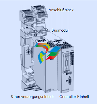
The basic hardware includes the controller unit, power supply component, bus modules, and associated cables.
- Easy expandability through a compact, modular design
- By selecting controller units with different performance characteristics, the system can be optimally adapted to each specific application.
- Decentralized programming via Ethernet network or serial channel
- I/O support for S200 I/O and S200L I/O centrally via serial I/O bus and decentrally via PROFIBUS-DP or ControlNet
- I/O support for S800 I/O decentrally via PROFIBUS-DP
- Communication capabilities with other control systems: MMS, SattLink, COMLI, SattBus, 3964R, and user-defined protocols (via serial channels)
- Units are connected to terminal blocks and connection blocks, which simplifies installation and increases reliability.
- Low installation and maintenance costs due to mounting on DIN-standard rails
- Mechanical coding prevents damage from incorrect installation
- CE
- ABB
## Software
The "Advant Control Builder" program provides the control system with a wide range of functions, such as logic functions, PID controllers, alarm processing functions, and communication capabilities with other control systems, human-machine interfaces (HMI), and systems from third-party manufacturers.
### Logic Functions
Logic functions, flip-flops, timers, and counters are included in accordance with IEC Standard 61131-3.
### PID Control
PID control functions are available in the controller system.
### Alarm Processing
Functions for alarm and event detection, as well as for alarm printing on local printers, are available.
### Communication
Communication with the programming tool is handled via a serial interface using the MMS protocol (SattLink).
Communication with other systems (e.g., HMI, SCADA, and control systems) can be handled
- via MMS or SattBus over Ethernet
- via the SattBus fieldbus
- via serial channels (RS232 or RS485). The available protocols include 3964R (as client), COMLI, and MMS (SattLink). User-defined protocols can also be used.
## Hardware
Up to 16 units can be connected to the Advant Controller 250, one of which is the controller itself, which can be selected from a range of models.
The units in the controller system and the I/O adapters of the central I/O system are interconnected via the controller bus.
All hardware units are equipped with LED indicators on the front panel, which display signal and error status, etc.
Each bus module can accommodate two hardware units. The connection blocks (200-BPP) are mounted on the bus modules, enabling easy signal connection.
### Controller Unit
The controller unit is a 32-bit high-performance single-board computer available in different models (PM253, PM254, and PM255). All controller units are equipped with a floating-point processor (FPU) to improve computing performance, as well as RAM memory and a real-time clock (both battery-buffered). In addition, all models are equipped with two serial RS232 channels and
a SattBus interface (except PM255, which has only one RS232 channel).
### Connection of Units
On the front of the unit, there is a start mode switch for setting different program modes and a reset button for the system.
The available controller models differ in terms of performance and memory configuration; further information can be found in the technical data.
### Power Supply Units
The power supply units of the Advant Controller 250 use an external 24V DC power supply, which provides isolated internal power for the controller and central I/O system.
#### 200-PSMG
200-PSMG is the master power supply unit, which also generates the clock frequency for the controller. The clock frequency is automatically set based on the actual system size.
#### 200-PSSG
200-PSSG is a slave power supply unit used in addition to 200-PSMG to improve power supply performance in larger system configurations.
### Communication Interface
External communication with the controller is conducted via interface units for Ethernet, SattBus, RS232, RS485, ControlNet, and PROFIBUS-DP.
The interface for all communication units is routed via the controller bus.
#### 200-CI232
200-CI232 is equipped with two non-isolated, asynchronous, serial RS232 channels with overvoltage protection. Connection is via connectors on the front or terminal blocks.
#### 200-CI485G
200-CI485G is equipped with two optically isolated, asynchronous, serial RS232 channels, which are tapped via terminal blocks.
Signals are galvanically isolated via optocouplers and converted to RS485 levels in the RS485 interface circuits. All signals are protected against overvoltage.
The unit can be used for both half-duplex two-wire connections and full-duplex four-wire connections.
An external 24V DC power supply is required for the two channels of the unit.
#### 200-CIE
200-CIE is equipped with an Ethernet channel according to IEEE 802.3 and performs all logic operations for communication.
The unit has an AUI port for connecting an external Ethernet transceiver (MAU) via a drop cable. The transceiver is powered via the AUI port.
200-CIE requires an external 24V DC power supply.
#### 200-CISB
Two galvanically isolated SattBus channels with supervisor function are available on the lower terminal block of the 200-CISB unit. Fieldbus communication for each SattBus channel is handled by a dedicated communication processor.
#### 200-CICN
200-CICN is an interface for the ControlNet network and is used for connecting the decentralized I/O system.
Each 200-CICN unit functions as an I/O scanner for decentralized I/O adapters of type 200-ACN. The decentralized I/O system is connected via coaxial cable or fiber optic cable.
200-CICN is connected to the ControlNet cable system via a 1m drop cable.
The unit is galvanically isolated from the ControlNet via a BNC connector on the front.
#### 200-CIPB/DP
200-CIPB/DP is an interface for the PROFIBUS-DP fieldbus and is used for connecting the decentralized I/O system.
200-CIPB/DP is a class 1 master unit and functions as an I/O scanner for decentralized I/O adapters of type 200-APB12.
The unit is connected to PROFIBUS-DP via a front-mounted connector.
### Empty Unit
#### 200-DU
The 200-DU empty unit is used in empty bus module slots in the controller system. It prevents mechanical and electrical damage to the controller bus.
### Bus Module
#### 200-BPN
200-BPN is used as a bus module for units of the Advant Controller 250. Each module has two slots in which units are secured with two snap locks.
The bus module is designed for mounting on DIN rails and can be fastened to the rail with an additional screw for use in environments with strong mechanical loads.
A maximum of 4 terminal blocks 200-BPP (2 for each hardware unit) can be mounted on the bus module.
Two mechanical rotary switches, each with 8 positions, prevent incorrect hardware units from being inserted and damaging the unit.
#### 200-BPP
200-BPP is a 12-pole terminal block for connecting power supply and communication signals to the controller system.
If the block is mounted above the hardware unit, the terminals are numbered from 13 to 24; when connected to the bottom, they are numbered from 1 to 12.
#### 200-BPT
200-BPT is a terminating resistor pair for terminating the controller bus.
### Cables
#### 200-CBA/L260, 200-CBA/L260V
These cables connect the controller bus module to the first central I/O adapter.
200-CBA/L260V is used for vertical mounting of the central I/O system. All required mounting parts are included.
### Miscellaneous
#### 200-BPF
200-BPF is a bus module connector used to connect two bus modules.
One bus module connector 200-BPF is supplied with each 200-BPN bus module.
### Decentralized I/O – ControlNet
#### I/O System
The ControlNet fieldbus can be operated via coaxial cable with a maximum length of 500 to 1000 m (3000 to 6000 m with repeater units), depending on the number of network nodes.
S200 and S200L I/O systems are used for the central I/O connection and can be mixed. S200, S200L, and S800 I/O systems can be used for the decentralized I/O connection.
When using fiber optic cables, a maximum distance of 7 km between two fiber optic repeater units can be bridged under certain circumstances. Additional fiber optic connections can be added.
Depending on the selected model, up to 512 I/O units can be connected to the Advant Controller 250.
The I/O adapters 200-ANN, 200-ACN, and 200-APB12 can each be operated with up to 8 I/O units. The I/O adapter CI830 can be operated with up to 24 I/O units. Up to seven additional rows of I/O units can be connected to the CI830 adapter via optical cables and optical interface units TB820.
The interface unit 200-CICN can be operated with a maximum of 248 I/O units (distributed across up to 15 adapters of type 200-ACN).
### Decentralized I/O – PROFIBUS-DP
The PROFIBUS-DP fieldbus can be operated with a maximum length of 100 to 1200 m, depending on the transmission speed. The interface unit 200-CIPB/DP can be operated with a maximum of 512 I/O units, distributed across up to 99 adapters 200-APB12 or up to 79 adapters CI830, or a combination thereof (total up to 99).
### Central I/O
The central I/O system is housed in the same control cabinet as the Advant Controller 250 and can be operated with a maximum of 48 I/O units (distributed across 6 adapters of type 200-ANN).
## Technical Data
### General Data
| Power Supply | +24 V (DC 19.2–30 V) including 5% ripple according to IEC Standard 61131-2 Type 1, i.e., +20%, -15% and max. 5% ripple |
|--------------|-----------------------------------------------------------------------------------------------------------------------|
| Temperatures | Operating: +5°C to +55°C; Non-operating: -25°C to +70°C |
| Humidity | Max 90%, no condensation |
| Protection Class / Approvals (if applicable) | IP20; CE mark; meets the requirements of EN 50082-2. Low Voltage Directive 73/23/EEC with amendment 93/68/EEC according to standards IEC 61131-2 (only applicable to units connected to AC 50–1000 V and/or DC 75–1500 V). UL approval for USA and Canada according to UL 508 (except 200-CIPB/DP) |
| Packaging Volume of Central System Units | 1–2 units: H 279 x W 360 x D 90 mm (9 dm³); 3–8 units: H 265 x W 265 x D 175 mm (12 dm³) |
### Controller Units
| Processor Type | |
|----------------|-----------------------------------------------------------------|
| PM253 | Motorola MC68020 |
| PM254 | Motorola MC68020 |
| PM255 | Motorola MC68060 |
| Clock Frequency | |
| PM253 | 16.7 MHz |
| PM254 | 28.8 MHz |
| PM255 | 50 MHz |
| Floating-Point Processor (FPU) | Yes |
| Memory and I/O Support for System and Application Program | |
| PM253V01 | 1 MB RAM, 32 I/O units |
| PM253V02 | 2 MB RAM, 64 I/O units |
| PM254V04 | 4 MB RAM, 128 I/O units |
| PM254V08 | 8 MB RAM, 256 I/O units |
| PM255V04 | 4 MB RAM, 256 I/O units |
| PM255V08 | 8 MB RAM, 512 I/O units |
| Status Indicators | |
|-------------------|-----------------------------------------------------------------|
| PM253 and PM254 / PM255 | Green LED indicators for power OK (PWR), SattBus signals (SB TD0, SB RD0), signals TD0, TD1, RD0, and RD1 of the serial channel; red LED indicators for errors and system stop. / Green LED indicators for power OK (PWR), and signals TD0 and RD0 of the serial channel; red LED indicators for errors and system stop; red/green LED for battery status. |
| Communication Channels | |
| Serial Channels Baud Rate | Max cable length: 15 m; 75, 110, 134, 150, 300, 600, 1200, 2400, 4800, 9600 (standard), 19200, and 38400 Baud |
| PM253 and PM254 | 2 RS232 channels. Channel 0: TD, RD, RTS, CTS, DCD, and DTR; Protocol: MMS (SattLink). Channel 1: RD and TD. Data bits: 7 or 8 (standard). Parity: odd, even, none. Stop bits: 1 (standard) or 2. Protocol: see 200-CI232. |
| PM255 | 1 RS232 channel. Channel 0: TD, RD, RTS, and CTS. Protocol: MMS (SattLink). |
| SattBus | 1 channel, supervisor function (not available for PM255). Protocol: see 200-CISB. |
| Real-Time Clock | Yes |
| Accuracy, Normal Mode | |
| PM253 and PM254 / PM255 | 10 ppm (approx. 6 min/year) / 100 ppm (approx. 60 min/year) |
| Accuracy, Battery-Buffered Mode | 50 ppm (approx. 0.2 s/year) |
| PM253 and PM254 | Lithium battery for memory retention and real-time clock (3.6 V; 1.75 Ah; type AA/R6/UM-3) including connection cable. |
| PM255 | Rechargeable NiMH battery for memory retention and real-time clock (4.8 V; 200 mAh; type 4 x V250H); buffer time approx. 1 hour. |
| Connections | One 200-BPP terminal block; one 9-pin D-SUB socket on the front. |
| Grounding | Directly via bus module 200-BPN |
| Power Supply | Via power supply unit 200-PSMG/PSSG |
| Internal Power Consumption (from 200-PSMG/PSSG) | Max 0.6 A |
| Bus Module Code | 5 |
| Weight | 0.430 kg without packaging; 0.500 kg with packaging |
| Dimensions | H 163 x W 45 x D 91 mm (excluding connections and snap locks) |
| Order Codes | PM253V01, PM253V02, PM254V04, PM254V08, PM255V04, PM255V08 |
### Power Supply Unit 200-PSMG
| Input | DC 24 V (19.2–30 V including max. 5% ripple); max. 1.3 A |
|---------------------|-------------------------------------------------------------------------|
| Input Protection | 2 A slow-blow, 250 V; IEC-127-3 microfuse TR5 |
| Inrush Current | Max 4 A for 10 ms |
| Voltage Drop Compensation | Max 0.3 ms |
| Output | DC 7–9 V; max. 2.2 A (1.8 A when additional 200-PSSG is used) |
| Clock Frequency | 4, 6, 8, and 12 MHz, automatically set based on system configuration size |
| Status Indicators | Green LED indicators for output voltage and clock output; Red LED indicators for initialization error and voltage error |
| Galvanic Isolation | AC 500 V effective between input and output |
| Connections | One 200-BPP terminal block |
| Grounding | Directly via bus module 200-BPN |
| Bus Module Code | 7 |
| Weight | 0.170 kg without packaging; 0.240 kg with packaging |
| Dimensions | H 163 x W 45 x D 91 mm (excluding connections and snap locks) |
| Order Code | 200-PSMG |
### Power Supply Unit 200-PSSG
| Input | DC 24 V (19.2–30 V including max. 5% ripple); max. 1.3 A |
|---------------------|-------------------------------------------------------------------------|
| Input Protection | 2 A slow-blow 250 V; IEC-127-3 microfuse TR5 |
| Inrush Current | Max 4 A for 10 ms |
| Output | DC 7–9 V; max. 1.8 A |
| Status Indicators | Green LED for output voltage; Red LED for voltage error |
| Galvanic Isolation | AC 500 V effective between input and output |
| Connections | One 200-BPP terminal block |
| Grounding | Directly via bus module 200-BPN |
| Bus Module Code | 7 |
| Weight | 0.170 kg without packaging; 0.240 kg with packaging |
| Dimensions | H 163 x W 45 x D 91 mm (excluding connections and snap locks) |
| Order Code | 200-PSSG |
### RS232 Communication Interface 200-CI232
| Number of Channels | 2 |
|--------------------------|-------------------------------------------------------------------------|
| Communication Protocols | COMLI (client and server), 3964R (client), MMS (SattLink) (client and server), and user-defined |
| Communication Interface | Asynchronous, serial RS232C communication for TD, RD, RTS, CTS, DCD, and DTR |
| Status Indicators | Green LED indicators for power OK and serial signals RD0, RD1, TD0, TD1, RTS0, and RTS1 |
| Galvanic Isolation | None |
| Transmission Speeds | 75, 110, 134, 150, 300, 600, 1200, 2400, 4800, 9600 (standard), 19200, and 38400 Baud; max. cable length: 15 m |
| Data Bits | 7 or 8 (standard) |
| Parity | Odd, even, none |
| Stop Bits | 1 (standard) or 2 |
| Max. Load on DTR | 5 mA |
| Power Supply | Via 200-PSMG/PSSG power supply units |
| Internal Power Consumption (from 200-PSMG/PSSG) | Max 0.2 A |
| Connections | Two 200-BPP terminal blocks; two 9-pin D-SUB sockets on the front |
| Bus Module Code | 8 |
| Weight | 0.200 kg without packaging; 0.270 kg with packaging |
| Dimensions | H 163 x W 45 x D 91 mm (excluding connections and snap locks) |
| Order Code | 200-CI232 |
### RS485 Communication Interface 200-CI485G
| Number of Channels | 2 |
|--------------------------|-------------------------------------------------------------------------|
| Number of Network Nodes | 32 per channel |
| Communication Protocols | COMLI (client and server), 3964R (client), MMS (SattLink) (client and server), and user-defined |
| Communication Interface | Asynchronous, serial RS485 communication for TD, RD, and RTS |
| Status Indicators | Green LED indicators for power OK and serial signals RD0, RD1, TD0, TD1, RTS0, and RTS1 |
| Galvanic Isolation | AC 500 V effective; channels are individually isolated from main logic and DC 24 V |
| Transmission Speeds | 75, 110, 134, 150, 300, 600, 1200, 2400, 4800, 9600 (standard), 19200, and 38400 Baud; max. cable length: 1200 m |
| Data Bits | 7 or 8 (standard) |
| Parity | Odd, even, none |
| Stop Bits | 1 (standard) or 2 |
| Power Supply | Via 200-PSMG/PSSG power supply units and external power supply (DC 24 V) |
| Internal Power Consumption (from 200-PSMG/PSSG) | Max 0.2 A |
| External Power Consumption | Max 0.1 A (from external DC 24 V) |
| Connections | Two 200-BPP terminal blocks |
| Bus Module Code | 8 |
| Weight | 0.220 kg without packaging; 0.290 kg with packaging |
| Dimensions | H 163 x W 45 x D 91 mm (excluding connections and snap locks) |
| Order Code | 200-CI485G |
### Ethernet Interface 200-CIE
| Number of Channels | 1 |
|--------------------------|-------------------------------------------------------------------------|
| Communication Standard | IEEE 802.3 (Ethernet) |
| Communication Protocols | SattBus (client and server), MMS (client and server) |
| Status Indicators | Green LED indicators for power OK, data transmit (TD0), data receive (RD0), and Ethernet traffic (NET); red error LED (software-controlled) |
| Galvanic Isolation | DC 500 V DC from 24 V DC power supply; according to IEEE 802.3 standard, the transceiver (MAU) must provide isolation between AUI cable and broadband coaxial medium. Any power supplied by the AUI must not exceed 0.5 A from the AUI voltage source. Further details can be found in ANSI/IEEE Std. 802.3 and SS-ISO 8802-3. |
| Transmission Speed / Access Method | 10 Mbit/s / CSMA/CD (Carrier Sense Multiple Access with Collision Detection) |
| Input Protection | 1.25 A slow-blow, IEC-127-3 microfuse TR5 |
| Power Supply | Via 200-PSMG/PSSG power supply unit and external power supply (DC 24 V) |
| Internal Power Consumption (from 200-PSMG/PSSG) | Max 0.25 A |
| External Power Consumption | Max 0.5 A at DC 19.2 V (typically 0.2 A) from external 24 V DC power supply (depending on transceiver type) |
| Connections | One 200-BPP terminal block; one front-mounted 15-pin D-SUB socket with slide lock |
| Bus Module Code | 8 |
| Weight | 0.340 kg without packaging; 0.410 kg with packaging |
| Dimensions | H 163 x W 45 x D 91 mm (excluding connections and snap locks) |
| Order Code | 200-CIE |
### SattBus Interface 200-CISB
| Number of Channels | 2 |
|--------------------------|-------------------------------------------------------------------------|
| Number of Network Nodes | 120 |
| Communication Protocol | SattBus (client and server) |
| Transmission Speed | 62.5 kBit/s |
| Access Method | Token passing |
| Status Indicators | Green LED indicators for power OK, data transmit (TD0, TD1), and data receive (RD0, RD1) |
| Galvanic Isolation | AC 500 V; channels are individually isolated via signal transformers |
| Connection | One 200-BPP terminal block |
| Power Supply | Via 200-PSMG/PSSG power supply unit |
| Internal Power Consumption (from 200-PSMG/PSSG) | Max 0.3 A |
| Bus Module Code | 8 |
| Weight | 0.250 kg without packaging; 0.320 kg with packaging |
| Dimensions | H 163 x W 45 x D 91 mm (excluding connections and snap locks) |
| Order Code | 200-CISB |
### ControlNet Interface 200-CICN
| Number of Channels | 1 |
|--------------------------|-------------------------------------------------------------------------|
| Communication Protocol | ControlNet |
| Access Method | CTDMA (Concurrent Time Division Multiple Access) |
| Galvanic Isolation | Isolation via signal transformers |
| Transmission Speed | 5 Mbit/s |
| Status Indicators | Green/red LED indicators for OK status and COM A and B (communication information); green LED for power OK |
| Power Supply | Via 200-PSMG/PSSG power supply unit |
| Internal Power Consumption (from 200-PSMG/PSSG) | Max 0.5 A |
| Connection | 75 Ω BNC on the front |
| Bus Module Code | 8 |
| Weight | 0.250 kg without packaging; 0.330 kg with packaging |
| Dimensions | H 163 x W 45 x D 91 mm (excluding connections and snap locks) |
| Order Code | 200-CICN |
### PROFIBUS-DP Interface 200-CIPB/DP
| Type | DP master class 1 |
|--------------------------|-------------------------------------------------------------------------|
| Number of Channels | 1 |
| Communication Protocol | PROFIBUS-DP |
| Transmission Speeds | 9.6; 19.2; 93.75; 187.5; 500; 1500; 3000; 6000; or 12000 kBit/s |
| Galvanic Isolation | None |
| Status Indicators | Green LED indicators for power OK, Ready, and Run; red error LED (for future use) |
| Power Supply | Via 200-PSMG/PSSG power supply unit |
| Internal Power Consumption (from 200-PSMG/PSSG) | Max 0.65 A |
| Connections | One 9-pin D-SUB socket |
| Bus Module Code | 8 |
| Weight | 0.270 kg without packaging; 0.330 kg with packaging |
| Dimensions | H 163 x W 45 x D 91 mm (excluding connections and snap locks) |
| Order Code | 200-CIPB/DP |
### Empty Unit 200-DU
| Bus Module Code | None |
|-------------------|-------------------------------------------------------------------------|
| Weight | 0.110 kg without packaging; 0.180 kg with packaging |
| Dimensions | H 163 x W 45 x D 91 mm |
| Order Code | 200-DU |
### Bus Module 200-BPN / Bus Module Terminating Resistor 200-BPT
| Number of Plugs (200-BPT) | One green start plug and one red stop plug |
|---------------------------|-------------------------------------------------------------------------|
| Internal Power Consumption (from 200-PSMG/PSSG) (200-BPT) | 0.2 A |
| Weight (200-BPT) | 0.010 kg |
| Dimensions (200-BPT) | H 32 x W 23 x D 17 mm |
| Order Code (200-BPT) | 200-BPT |
| Number of Slots (200-BPN) | 2 |
|---------------------------|-------------------------------------------------------------------------|
| Internal Power Consumption (from 200-PSMG/PSSG) (200-BPN) | Max 0.04 A; the power consumption is included in the specifications for central system units and does not need to be considered separately when calculating total power consumption. |
| Connections (200-BPN) | The number of 200-BPP terminal blocks depends on the installed units. 2 x 32-pin Euro connectors for electrical connection of bus module and units |
| Mounting (200-BPN) | On 35 x 7.5 mm rail according to DIN standard EN 50022 |
| Weight (200-BPN) | 0.170 kg without packaging; 0.240 kg with packaging |
| Dimensions (200-BPN) | Height: 239 mm with one terminal block; 163 mm without terminal block. Width: 91 mm excluding 5 mm wide connecting clip to next bus module. Depth: 43 mm (127 mm including unit with front connectors and DIN rail). |
| Order Code (200-BPN) | 200-BPN |
### Controller Bus Cable 200-CBA/L260
| Rail Distance (Center to Center) | Max 255 mm |
|----------------------------------|-------------------------------------------------------------------------|
| Weight | 0.092 kg |
| Order Code | 200-CBA/L260 |
### Controller Bus Cable 200-CBA/L260V
| Weight | 0.092 kg |
|--------------|-------------------------------------------------------------------------|
| Order Code | 200-CBA/L260V |
### Terminal Block 200-BPP
| Terminal Screws | 12 |
|-----------------|-------------------------------------------------------------------------|
| Cable | Solid or flexible 0.5–2.5 mm² (AWG 20–AWG 12) |
| Weight | 0.070 kg |
| Dimensions | H 60 (only 37 mm when installed) x W 45 x D 43 mm |
| Order Code | 200-BPP |
### Programming Cable 200-CPC (Optional)
| Connections | One 9-pin D-SUB socket |
|-------------|-------------------------------------------------------------------------|
| Weight | 0.125 kg |
| Length | 3.00 m |
| Order Code | 200-CPC |
ControlNet is a trademark of Allen-Bradley Company, Inc., a Rockwell International Company. Windows is a registered trademark of Microsoft Corporation.
-
 Basler Electric SGC-250. Synchronous Generator Controller
 -
 Basler Electric BE1-50/51 Plug and Play and Retrofit Relays
 -
 Basler Electric DECS-2100. Digital Excitation Control System
 -
 Basler Electric DECS-250E, Digital Excitation Control System
 -
 Basler Electric BE1-700V, Voltage Only Digital Protective Relay
 -
 Basler Electric DECS-250. Digital Excitation Control System
 -
 Basler Electric DECS-450. Digital Excitation Control System
 -
 Basler Electric DECS-150. Digital Excitation Control System
 -
 Basler Electric ES-49. Temperature Relay
 -
 Basler Electric ES-81O/U, ES-81O,ES-81U Overfrequency Relay
 -
Basler Electric ES-74V, DC Voltage Sensing Relay
-
Basler Electric ES-27/59. Under/Overvoltage Relay
-
 Basler Electric ES-27. Undervoltage Relay
 -
 Basler Electric ES-25. Sync-Check Relay
 -
 Basler Electric ES-47, ES-47N Phase Sequence Relay
 -
Basler Electric ES-37.ES-37/51 Undercurrent Relay
-
 Basler Electric ES-32. Reverse Power Relay
 -
Basler Electric ES-59. Overvoltage Relay
-
 Basler Electric ES-55. Power Factor Relay
 -
 Basler Electric DGC-2020HD, Digital Genset Controller
 -
 Basler Electric BE1-FLEX, Protection, Automation, and Control System
 -
 Schneider GUTOR OC0935 Power Factor Sampling Board
 -
 Schneider GUTOR OC0922 Analog Signal Isolation Board
 -
 Schneider GUTOR OC0908 Battery Voltage Detection Board
 -
Schneider GUTOR OC0947 Temperature / IGBT Sampling Board
-
 Schneider GUTOR OP2601 Communication Expansion Board
 -
 Schneider Electric GUTOR OP2312 bypass control board
 -
 Schneider Electric GUTOR OP2130 Cooling Fan Monitoring & Control Board
 -
 Schneider Electric GUTOR OP2010 Battery Test Board / Battery Management Diagnostic Card
 -
Schneider Electric GUTOR OP2552 Three-phase Power Connection Board Assembly
-
 Schneider Electric GUTOR OP1922A Parallel Control Board / Load-Sharing Synchronization Module
 -
 Schneider Electric GUTOR OP6290B Inverter Feedback Acquisition Board / Signal Scaling Module
 -
Schneider GUTOR OP6280 Basic Signal Board
-
Schneider Electric GUTOR OP2456 / OP2456B Main control board
-
 Schneider Electric GUTOR OP2452 Power Plug-in Panel
 -
 Schneider Electric GUTOR OP2450 Parallel Communication Board
 -
Schneider Electric GUTOR OP2406 Interface Fuse Monitoring Board
-
 Schneider Electric GUTOR OC0919 High-Power Semiconductor Module
 -
 Schneider Electric GUTOR OP6281A System Logic Interface Board
 -
 Schneider Electric GUTOR OP6285A Power Signal Acquisition Board
 -
 Schneider Electric GUTOR OP2438 Fan Monitor & Drive Protection Board
 -
Schneider Electric GUTOR OP2446 Main Control CPU Board
-
 ROLLS-ROYCE CE05-00 Steering Gear Control Module
 -
 ROLLS-ROYCE MARINE AS-BRATTVAAG WRC1021A CONTROLLER CARD
 -
ROLLS ROYCE DECK MACHINERY MPC-300-A7029099 TERMINAL CONTROLLER UNIT
-
 ROLLS-ROYCE HELICON THRUSTER CONTROL PANEL LF90S-01-06
 -
 Rolls-Royce PCC1030C Panel Controller Card
 -
 Rolls-Royce RRDIO15 Remote Digital Input/Output Module
 -
 Rolls-Royce TDI-11 Pitch & Direction Indicator Module
 -
 Rolls-Royce CCN 01 CANman Controller Network Module
 -
 Rolls-Royce SLIO 01 CANman Controller Network Module
 -
 Rolls-Royce MPC-210 Winch & Propulsion Control Module
 -
Rolls-Royce MTI-144 Engine Control Module
-
 Rolls-Royce Tenfjord FB10-002 Steering Gear Module (E-4500-40-1)
 -
 ROLLS ROYCE MARINE AS CIRCUIT BOARD (PCB) RRAI016
 -
 Rolls-Royce Marine AS PIP6-1 Marine Controller
 -
 ROLLS-ROYCE MPC-300 STARTER CONTROL UNIT A7029099
 -
 Rolls-Royce Data Respons MPCF1-10.4" Maritime Panel Computer
 -
 ROLLS-ROYCE MARINE OLC-40009 PCB CARD
 -
Rolls-Royce Marine Brattvaag WRC1021B Controller Board
-
 ROLLS-ROYCE CCN 01 & ROLLS-ROYCE SLIO 02 CANMAN CONTROLLER NETWORK
 -
.png) ROLLS-ROYCE ATC-3-A7033172 AQUAMASTER TURNING CONTROLLER
ROLLS-ROYCE ATC-3-A7033172 AQUAMASTER TURNING CONTROLLER -
 ROLLS-ROYCE POSCON V.3 JOYSTICK MODULE 6459
 -
.png) Rolls-Royce Marine 389-496-00 Joystick Remote Control Panel 6799-W, 389-996-00
Rolls-Royce Marine 389-496-00 Joystick Remote Control Panel 6799-W, 389-996-00 -
 Rolls-Royce data respons 10.4'' Panel Computer 98H010A0000I/R10I53S
 -
 Rolls-Royce H1127.0101 Marine Controller 000068308
 -
 Rolls-Royce CU40-0106-50 Steering Gear Control Panel
 -
 Beckhoff Polaris CP7011-1002-0010 operator operator HMI display 30.5 cm
 -
 Beckhoff AM8052-0JH1-0000 Servomotor 10.7 Nm (M0), F5 (104 mm)
 -
 Beckhoff BX5100-0000 CANopen Bus Terminal Controller
 -
 Beckhoff CX9020-0115 PLC Module CX90200115
 -
 Beckhoff module EJ7211-0010 EtherCAT plug-in module
 -
 BECKHOFF AX5203-0000 Servo Driver
 -
 BECKHOFF CP6201-0001-0020 24VDC UNMP
 -
 Beckhoff CX5120-0135 Embedded PC CPU Module
 -
 BECKHOFF C5240-0020/000224115 Plc Module
 -
 Beckhoff CP2918-0000 nelCP29xx-0000Pa | Multi-touch built-in Control Panel with DVI/USB Extended interface
 -
 Beckhoff CX2020-0122 Embedded PC Controller
 -
 Beckhoff C6640-0040 Control Cabinet Industrial PC 7-Slot
 -
 BECKHOFF CONTROL CABINET INDUSTRIAL PC - C6930-1062-0050
 -
 Beckhoff Automation EtherCAT Terminal EK1100 EK1122
 -
Beckhoff CP6533-0001-0060 IPC
-
 Beckhoff EK9500 | EtherNet/IP™ Bus Coupler
 -
 Beckhoff CP6202-1047-0050 - An industrial-grade embedded panel computer.
 -
 Beckhoff C6650-0040 Industrial PC
 -
 BECKHOFF CX5230-0185 / 000119805 PLC Module
 -
 BECKHOFF EL4732 | EtherCAT Terminal, 2-channel analog output, voltage, ±10 V, 16 bit, oversampling
 -
 Beckhoff CP6202-0001-0010 Economy Built-In Panel
 -
 Beckhoff AX5206-0000-0202 Digital Compact Servo Drives 2-channel
 -
 Beckhoff CP6606-0001-0020 7-inch Economy Panel PC
 -
 Beckhoff CPU basic module CX2020-0155 + power supply module CX2100-0004
 -
 Beckhoff CP2913-000 Multi-Touch Display
 -
 Beckhoff CP6500-1012-0060 14250369 Control Cabinet
 -
 Beckhoff CP7902-0001-0000 Economy Control Panel with DVI/USB Extended interface
 -
 Beckhoff C6920-0010 Control cabinet Industrial PC
 -
 BECKHOFF C3640-0050 Build-in Industrial PCs
 -
 Beckhoff KL6023-0000 KL6023 EnOcean Wireless-Adapter
 -
 Kollmorgen AKM54G-ANC2DB00 servo motor
 -
 Kollmorgen AKD-P00606-NBCN-0000 Servo Drive
 -
Kollmorgen S200 Series S20350-VTS SERVO DRIVE
-
 KOLLMORGEN AKD-P00606-NBCC-I000 SERVO DRIVE
 -
 Kollmorgen MV65WKS-CE310/22PB Servo Drive Control Module
 -
 Kollmorgen S20360-VTS-021 Servo Drive
 -
 KOLLMORGEN CR06550 High-precision digital servo amplifier
 -
 KOLLMORGEN DBL5N01050-03S-VV0-S40 3-Phase AC Synchronous Brushless Servo Motor
 -
 KOLLMORGEN S70301-NANANA-024 SERVO DRIVE
 -
 Kollmorgen S20360-VTS S200 Series Servo Drive
 -
 Kollmorgen RBE-03011-A00 Brushless Frameless Servo Motor
 -
 KOLLMORGEN AKD-T00306-NBAN-0000 INPUT SERVO DRIVE
 -
 KOLLMORGEN S700 Servo Controller S70302-NANANA
 -
 Kollmorgen AKD-P00607-NBEC-0000 400/480VAC 4.40KVA Servo Drive.
 -
 KOLLMORGEN S70102-NANANA SERVO DRIVE
 -
 KOLLMORGEN AKM21E-ANSNEH02 PM Servo Motor & PRD-AMPE25EB-00 Servo Drive Array
 -
 KollMorgen SC1R06260 Servo Drive 1.4/2.2 KVA 115230 Vac
 -
 Kollmorgen AKD-P00306-NBAN-0000 Servo Drive
 -
Kollmorgen TTB2-2042-3052-A DC Motor Industrial Drive 5.5A 185 oz/in
-
 KOLLMORGEN SERVOSTAR 610-AS SERVO AMPLIFIER_SERVOSTAR610AS_S61001
 -
 KOLLMORGEN PRD-0016400P-10 & PRD-0016600D-30 Axis Control System Modules
 -
KOLLMORGEN Seidel DBL5N01700-03S-000-S40 Servo Motor
-
 Hirschmann RS20-1600M2T1SDAEHH03.1.02 Rail Switch
 -
 Hirschmann BRS30-24TX Industrial Rail Switch
 -
 Hirschmann RSPM20-4T14T1EV9HHS999.9.99 Managed Ethernet Switch
 -
 Hirschmann BELDEN RS40-0009CCCCSDAPHH09.0.14 / RS400009CCCCSDAPHH09014
 -
Hirschmann RS40 Rail Switch RS40-0009CCCCSDAE
-
 Hirschmann BELDEN RS30-0802T1T1SDAP / RS300802T1T1SDAP Fully Managed Layer 2 Compact Rail Switch
 -
 Hirschmann BELDEN RS20-0800M2M2SDAUHH / RS200800M2M2SDAUHH
 -
 Hirschmann EAGLE30-04022O6TT999SCCY9HSE3F Industrial Firewall Router Switch
 -
 Hirschmann RS20-1600T1T1SDAEHH09.0.14 RS20 Rail Mount Ethernet Switch


