
rolls-royce User Manual Rolls-Royce Helicon X3 P&T Control System
Purpose
The purpose of the Helicon X3 User Manual is to provide the necessary information to
plan and perform a safe and correct operation of the installed delivered system, as well
as under-standing the basic functionality of the equipment. The User Manual covers
both operational and technical aspects of the system.
The personnel involved in using the system must have relevant experience and training
with regards to the use of such systems.
2 Warranty
The product has a limited warranty. Please note that the warranty will be void if the
equipment is misused or not handled in accordance to prescribed standards, for example
dismantling the equipment to a level greater than described.
3 Contents
This manual contains the following chapters:
Chapter Contents
1. Introduction This chapter specifies the purpose and target groups for the
manual. It also contains list of used abbreviations and a
specification of the document conventions.
2. Safety This chapter specifies safety instructions to follow when
operating and maintaining system.
3. System Description This chapter briefly describes the system components, the
system design and the functionality.
4. Delivery Specification This chapter specifies the delivered equipment.
5. Technical Data This chapter contains technical specifications and
performance data.
6. Operating Instructions This chapter describes how to use the Helicon X3 system.
7. Maintenance Instructions This chapter describes how to maintain the Helicon X3
system, including both preventive and corrective actions.
8. Trouble Shooting This chapter describes how to act when a malfunction occur
in the Helicon X3 system.
9. Contact Information This chapter contains contact information for Rolls-Royce
Marine, Dept. Propulsion Ulsteinvik and Rolls-Royce World
Wide Support Organization.
10. Spare Parts This chapter specifies recommended spare parts for the
Helicon X3 system.
11. Tools This chapter describes required and recommended tools for
the maintenance of the system to use during the installation.
12. Design Drawings This chapter consists of design drawings that serve as an
information source about the installed system for the
installation.
13. Revision This chapter contains the revision history for the total binder.
14. Subsuppliers Manuals This chapter contains documentation from other suppliers
than Rolls-Royce, if such has been delivered by RRM.
Target Groups
The User Manual is primarily intended for the user of the system. The user must be
properly trained in using and maintaining the system.
The installation of the system components must be made by yard mechanics with
experience in fitting marine electronic equipment. Cabling into the units, wire
termination and screen/shield termination should be made by yard electricians that have
a certificate of apprenticeship or equal qualification on ship electrical installation.
Commissioning and testing must be carried out by field service personnel from RollsRoyce Marine, Dept. Propulsion Ulsteinvik or qualified service engineers from RollsRoyce Marine Global Support Network (GSN).
5 Terms and Abbreviations
Abbreviation or term Description
AC/DC Alternating Current/ Direct Current
AQM Aquamaster
AZP Azipull Thruster
BC Backup Control
CAN Controller Area Network
CCW Counter Clock Wise
CW Clock Wise
DC/DC Direct Current/ Direct Current
ESD Electrostatic Discharge
EU European Union
GSN Global Support Network
GUI Graphical User Interface
I/O Input/Output
LCD Liquid Crystal Display
LED Light Emitting Diode
MP Main Propulsion
NC Normally Closed
PMS Power Management System
PTI Power Take In
PTO Power Take Out
RC Remote Control
RPM Revolutions Per Minute
RR Rolls-Royce
RRM Rolls-Royce Marine
RUP Running Up/Down Program
SAT Sea Trial Acceptance Test
STBD Starboard
TCNS Thruster Compass Nozzle Swing-Up
TT Tunnel Thruster
V Volt
Introduction
This chapter provides information regarding safety precautions that must be taken to
prevent injury to people and damage to equipment.
Whoever is responsible for the installation, operation or maintenance of this RollsRoyce system, is obliged to read this chapter and fully understand its content before any
installation, operation or maintenance of the system may take place.
2 Disclaimer
Undertaking any work envisaged by this document may either directly or indirectly
create risks to the safety and health of the person undertaking the work or the product
and/or its components while the work is being performed.
It is the responsibility of the user to protect the health and safety of the persons
undertaking the work as well as risk to the product and/or its components. Therefore the
user must ensure that appropriate controls and precautions are identified and taken in
relation to the work envisaged by this document in accordance with the relevant
statutory and legal and industrial requirements.
Neither this document, nor its use, in any way absolves the user from the responsibility
to ensure that the controls and precautions referred to above are implemented.
If any Rolls-Royce product design related features which could create risks to persons,
the product and/or its components are identified, Rolls-Royce should be contacted
immediately.
It is the user's responsibility to make all relevant hazard identifications and risk
assessments of all the activities associated with the use of this document.
It is the user's responsibility to design and implement safe systems of work and to supply
safe equipment (including, without limitation, safety equipment) and training
(including, without limitation, health and safety training) to anyone using this document
to work on products to which it relates.
A user without relevant experience of working in accordance with this document, or
with products to which it relates, should seek appropriate advice to identify the health
and safety controls and precautions that need to be taken while working.
Technical assistance can be sought from Rolls-Royce and will be subject to RollsRoyce's terms and conditions.
3 Safety Instructions
This Rolls-Royce system is a remote control system that is controlling propulsion units
on the vessel. By operating the system, the thrusts direction and pitch/speed
performance can be controlled.
The operator must at all times be aware of:
• Consequences of operating the system to prevent injury to people, damage of
equipment, damage to the vessel operated and damage to the surroundings.
3.1 Safety Functions
A number of safety functions are included in the system. These functions will become
operative if a failure should occur in the propeller control system itself, or in external
systems connected to the propeller control system.
Note: The backup control system has only interface to the control levers. The
backup control system does not have interface to external control
systems like Dynpos, Joystick or Autopilot
Note: No azimuth restrictions or load control functions are included in the
backup system. When operating using the backup system, the operator
must be careful not to overload the engine or the propeller system. If a
load control system is included in the Rpm Drive, this will still be in
operation.
Note: The safety functions described underneath will only be available if the
thruster(s)/gear(s) have got the described function in the first place.
3.1.1 Pitch Control
The pitch control is one of the redundant functions in the control system. The backup
control system will automatically be engaged if a serious failure occurs in the normal
control system. This includes loss of power supply to the normal control system, halt in
the normal control cpu, failure on the normal control order potentiometer in the lever on
the manoeuvre station currently in command, failure on the normal control field bus and
failure on the normal control feedback potentiometer. Alarm will be given in the control
system and in the ship's alarm system.
3.1.2 RPM Control Electric Engine
The RPM control is a redundant function in the control system. The backup control
system will automatically be engaged if a serious failure occurs in the normal control
system. This includes loss of power supply to the normal control system, halt in the
normal control cpu, failure on the normal control order potentiometer in the lever on the
manoeuvre station currently in command and failure on the normal control field bus.
Alarm will be given in the control system and in the ship's alarm system.
3.1.3 Azimuth Control
The azimuth control is a redundant function in the control system. The backup control
system will automatically be engaged if a serious failure occurs in the normal control
system. This includes loss of power supply to the normal control system, halt in the
normal control cpu, failure on the normal control order potentiometer in the lever on the
manoeuvre station currently in command, failure on the normal control field bus and
failure on the normal control feedback potentiometer. Alarm will be given in the control
system and in the ship's alarm system.
3.1.4 Dynpos and Joystick
If operating using an external Dynpos or Joystick system and a failure occurs either on
the pitch order, the rpm order or the azimuth order signal from the external system, the
external system is disengaged and the propeller responds to the control lever order on
the manoeuvre station in command. Alarm will be given in the control system and in the
ship's alarm system.
3.1.5 Autopilot
If operating using an external autopilot system and the azimuth lever order on the
manoeuvre station in command is changed more than the adjustable limit, normally 20
degrees, the autopilot is disengaged and the thruster will respond to the control lever.
This is indicated by blinking the Autopilot button, and the buzzer will sound until the
Autopilot button is pressed to acknowledge the mode change back to lever control.
Safety Messages
Safety messages in this manual are always accompanied by a safety alert symbol and a
signal word. The safety alert symbol is used to alert the reader about a potential risk of
personal injury or damage to the equipment.
The following types of safety messages are used within this manual:
Warning: Risk of... Indicates the presence of a hazard which could result in death or
personal injury.
Caution: Indicates the presence of a hazard which could result in damage to
equipment or property and seriously impact the function of the equipment.
Note: Alerts the reader to relevant factors and conditions which may impact the
function of the equipment.
General
This chapter provides an overview of the Helicon X3 system and a technical description
of the main components that give the required knowledge about the system.The figures,
drawings and text in this chapter are general and may not comply to the actual
installation on the vessel. For details on the delivered equipment, see chapter 4 Delivery
Specification.
2 System Overview
The Helicon X3 remote control system is a micro-processor-based system, controlling
the propulsion units on the vessel. The following main functions are included:
• Combinator control, allowing accurate and reliable control of the propeller pitch and
motor speed (RPM). The combinator curve optimises the pitch/speed performance to
give the best operational conditions and fuel economy.
• Pitch control, allowing accurate and reliable control of the thruster pitch.
• Speed control, allowing accurate and reliable control of the motor speed (RPM).
• Direction control, allowing accurate and reliable control of the thrust direction.
• Follow-up backup control from control levers.
Helicon X3 consists of the following main components:
• Instruments, screens, levers and Viewcon on the bridge (1).
• Electrical cabinets in the instrument room (2) and thruster room (4).
• Instruments, screens and levers in the engine control room (3).
Helicon X3 may interface several external systems (5), like Dynamic positioning
systems and Autopilots.
Design
3.1 Lever
Each thruster has its own lever. Their main functions are:
• Control of pitch, RPM and azimuth direction (dependant of application)
• In operation
• Command transfer
• Lever in command
• Back-up control
• Alarm
The control lever has integrated buttons and indication lamps for command transfer,
backup system on/off, alarm indication/buzzer and push button for reset of buzzer. The
display in the base shows set command (pitch and direction) from the lever.
The lever contains two redundant electronic circuits, one for the normal control system
and one for the backup system.
Control Panel
The control panel (touch screen) is the main user interface for the operator and gives an
overview of all the thrusters on the vessel. It shows the status of the system, indicates
thruster forces, displays alarms, and shows selected modes. The flat button on the top of
the screen is for dimming the illumination of the LCD display.
The screen is divided in two areas: a menu area in the left part of the screen, and a bigger
command area to the right. The menu buttons to the left selects the content of the
command area.
There is one command page for each thruster, in addition to one system overview page
and one alarm page. The overview page shows the most essential information for all
thrusters, but to activate functions or to view all available information for a thruster, the
particular thrusters' page must be selected.
The graphical design is based on the following principles:
• All functions pages are only one click away
• Large and simple buttons which are easy to read.
• Same design theme for all clickable objects.
• To avoid unintentional activation of functions, all function activation buttons require
press on the accept button to proceed.
Colour on button Function
A ring around the button The button is push able
Blue Indicates current status
Green Start
Red Stop
2 buttons flashing Select function
1 button flashing The button has been activated and will flash until the function
has started/stopped
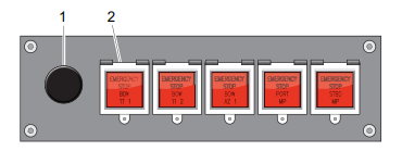
Emergency stop and dimmer panel (optional)
The emergency stop is used to shut down the thrusters immediately.
There is one button per thruster unit.
The wheel (1) is used for dimming the background light on the indicators situated on the
same control station.
The dimmer may be delivered in a separate panel, if the emergency stop buttons are not
part of the delivery scope.
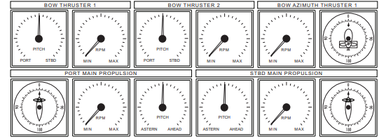
Indicators
The indicators give feedback on various data and can be found on the bridge and in the
engine control room.
There are three main types of indicators:
• Azimuth indicator
• RPM indicator
• Pitch indicator
In addition a bridge order indicator may be delivered on some vessels.
Viewcon
Network cabinet
The network cabinet(s) contains several switches. The network cabinet(s) connects the
panel PCs and the controller cabinets.
Network
Operator stations and electronic units are linked together in an Ethernet network. The
network is single and may contain several separate switches.
(CAN bus is the internal communication between levers, I/O modules and Marine
Controller.)
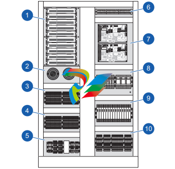
1. Rolls-Royce Marine Controller (Normal)
2. Rolls-Royce Marine Controller (Backup)
3. I/O modules
4. Power distribution
5. Network switches and terminals
6. Signal isolation amplifiers (optional)
7. Power Distribution
8. Main power supply (AC) / fuses
9. Backup power supply (DC) / fuses
3.7 I/O Cabinet
The I/O cabinet is often located in the thruster room near sensors and actuators. This
cabinet distributes signals to the different propulsion/thruster units. There is one I/O unit
per propeller/thruster.
The I/O cabinet sends signals to the actuators on the propellers/thrusters and receives
signals from the sensors. There is CAN bus communication between each I/O and
controller cabinet.
Normal Control
The output from the pitch controller is computed on the basis of the input signals from
pitch lever and the actuator position feedback.
Lever and feedback signals are scaled and checked against adjustable limits, with
corresponding alarm for exceeding the normal range. The levers have one set of
adjustments (minimum, zero and maximum) for each manoeuvre station. Multiple sets
of feedback adjustments (minimum, zero and maximum) are available for various
engine power take-outs.
In combined mode the lever signal is modified in a Combinator program, see chapter
Pitch and RPM Combinatory (combined Control).
4.1.2 Backup Control
The Backup Control system consists of closed loop control identical to the Normal
Control system. The Backup Control is a separate system, and is independent of the
Normal Control system. A system failure in the Normal Control system will
automatically switch to and engage the Backup Control.
Lever order signals and feedback are monitored and verified against adjustable alarm
limits. If the signals exceed the limits this will release an alarm to the alarm plant and
both visual and audible system failure alarm will be actuated at the manoeuvre stations.
4.1.3 Backup Control Operation
If a failure occurs on important parts of the Normal Control for the Pitch, Azimuth or
RPM Control function, the control will automatically be switched over to the Backup
Control system. A system failure audible and visible alarm will be activated on each of
the control panels.
The thruster control will continue to follow the lever in command and transfer is done
by using the common in command buttons. The command can be transferred between
all bridge position and the bridge control levers will continue to work as in normal
control.
A failure that occurs on important parts of the Backup Control for the Pitch, Azimuth or
RPM Control function will not affect the Normal Control system. If a system failure
occurs on the Backup Control an audible and visible alarm will be activated on each of
the control panels.
4.1.4 Backup Control Limitations
The Backup Control system has only interface to the control levers. The Backup Control
system does not have interface to External Control systems like Dynamic positioning
systems, Joysticks or Autopilots.
No pitch reduction or load function are included in the Backup system.
When operating using the backup system, the operator must be careful not to overload
the engine or the propeller system.
4.1.5 Local Control
If both the Remote Control system and the Backup Control should fail it is possible to
operate the propeller pitch locally from the pitch control valve.
4.1.6 Pitch Indication
The Pitch Indication system is independent of the Normal Pitch Control system by
means of separate transmitters and electronic circuits. The pitch indicators are connected
in series and are driven from the Backup Control system.
4.1.7 Pitch Order Scaling
The system may need to reduce the pitch order for different reasons. The pitch reduction
can either be activated from a digital or anlogue input signal.
To reserve engine power to heavy consumers as alternators, fire pumps, etc., it may be
necessary to reduce the available propeller output power. This is normally done by
means of a fixed propeller pitch reduction.
If the drive motor is a diesel engine the system is prepared to handle a fuel limiter
contact, from the RPM governor (i.e. high scavange air pressure). If the contact is closed
the pitch order will stop increasing to a higher value, only decrease of pitch order against
zero is possible.
For azimuth thrusters, a pitch reduction will be activated if the azimuth order is changed
faster then the thruster azimuth servo can follow.
4.2 Thruster Azimuth Control
The azimuth control function is to obtain the correct thruster azimuth position in
accordance to the control lever order. Valve controlled hydraulic motors or frequency
controlled electro motors perform the positioning of the thruster azimuth.
Detailed information regarding the hydraulic system or motor data is available in the
Thruster Instruction manual.
Note: Test point angle signals are ranged +/- 100%, representing +/- 180 degrees.
Some test points are named with degrees, displaying the angle in degrees
(+/- 180 degrees).
4.2.1 Normal Control
The azimuth controller computes the thruster position and order on the basis of signals
from the thruster feedback and control levers. A two-wiper linear potentiometer
provides two outputs with 90 degrees of phase shift named cosine and sine phase
respectively.
The lever order signals and feedback signals are monitored and verified against alarm
limits. If the signals exceed the limits this will release an alarm to the alarm plant with
a visual and audible system failure alarm on the manoeuvre stations.
4.2.2 Backup Control
The Backup Control system consists of closed loop control identical to the normal
control system. The Backup Control is a separate system, and is independent of the
Normal Control system. A system failure in the Normal Control system will
automatically switch to and engage the Backup Control.
Lever order signals and feedback are monitored and verified against adjustable alarm
limits. If the signals exceed the limits this will release an alarm to the alarm plant with
a visual and audible system failure alarm on the manoeuvre stations.
4.2.3 Backup Control Operation
If a failure occurs on important parts of the Normal control for the Pitch/Azimuth/RPM
control function, the control will automatically be switched over to the backup control
system. A system failure audible and visible alarm will be activated on each of the
control panels.
The thruster control will continue to follow the lever in command, and command
transfer is done by using the common in command buttons. The command can be
transferred between all bridge position and the bridge control levers will continue to
work as in Normal Control.
A failure that occurs on important parts of the Backup control for the Pitch/Azimuth/
RPM control function, will not affect the Normal control system. If a system failure
occurs on the Backup Control an audible and visible alarm will be activated on each of
the control panels.
4.2.4 Backup Control Limitations
The backup control system has only interface to the control levers. The backup control
system does not have interface to external control systems like Dynpos, Joystick or
Autopilot.
Note: No azimuth restrictions or load control functions are included in the
backup system.
When operating using the backup system, the operator must be careful not to overload
the engine or the propeller system.
4.2.5 Local Control
Local control is used if both the normal control and the backup control fail to operate the
thruster azimuth. The thruster azimuth can be operated locally on the actuator unit. The
Control System must first be disconnected from the actuator unit. This can be done by
means of the Local Control switch mounted in front of the Actuator Interface Unit, or
by disconnecting the plug from the actuator unit. If frequency converter used, operate
service switch inside converter cabinet.
The Thruster Instruction Manual will give more details for Local Control operation.
4.2.6 Azimuth Indication
The azimuth indication system independent of the normal control system by means of
separate transmitters and electronic circuits. The Azimuth indicators are connected in
series, and are driven from the Backup Control system.
RPM Control
The RPM Control function system controls the speed signal to the frequency converter
for electrical drives or the engine governor for diesel or gas engines.
4.3.1 RPM Control Electric Drive Motor
The RPM Control system includes selection of different operational modes:
• Separate Mode
• Combined Mode
Selection between modes is possible by means of push buttons. RPM Control can be
managed from engine control room only or from additional control panels.
4.3.2 External RPM Control
External RPM order signals from system as DP/Joystick/Auxiliary systems can be
connected to the rpm controller.
The external rpm signal are checked against adjustable preset limits. Any error
conditions on the rpm input signal will initiate a warning to the alarm plant and an error
message will be displayed on the control panel.
4.3.3 RPM Order Output
The output signal from the controller is scaled to meet the actuator signal range from idle
to full rpm, and then fed to external governor, IP converter or frequency converter. The
output will follow a linear curve between idle and full rpm order.
The RPM output rate of change is adjustable and can be adapted to the engine/frequency
converter reversing speed from idle to full rpm (increasing order) and vice versa
(decreasing order).
4.3.4 Propeller/Shaft RPM Indication
The propeller/shaft RPM indicators are connected in series and are driven from the
Backup Control system.
4.4 Command Transfer
The term Command transfer is used to describe the procedure performed when the
control is transferred between manoeuvre stations without acceptance on either of the
stations. This is normally the procedure between wheelhouse (bridge) stations.
5 Location of Manufacturing Number
5.1 Marking Locations
Electrical cabinets and junction boxes are physically marked with a unique tag, and also
on all applicable drawings. The I/O cabinets are marked with the Rolls-Royce logotype
in the upper left corner.
The Rolls-Royce logotype is imprinted in remote control panels, alarm panels and cabin
panels.
Cables are marked with a cable tag at both ends.
5.1.1 Company Identification
The Rolls-Royce Company Identification sticker shows where the product has been
produced and is found on discrete places on all delivered items, e.g. on the inside of the
cabinet doors.
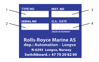
Pos Denomination Meaning
1 TYPE NO Corresponding drawing number with the revision letter in
closed brackets
2 SERIAL NO Production order number
3 INST. NO Installation number
4 Q.A. DATE Date and signature by test responsible
Technical Specification
Propulsion & Thruster Control System
Project no. : 20-12-00136
Version : -
Vessel type (design) : UT535E
Customer Project no. : RRM STO – P12/7210
Shipowner :
Shipyard :
Yard no. :
Rolls-Royce Marine
Propulsion Ulstein Unit nos : 2xTT CP (bow), 2xUS FP (main)

-
 HIRSCHMANN MSM20-M2M2M2M2SY9HH9E Ethernet media modul
 -
 HIRSCHMANN SPIDER-PL-20-05T1999999TWVHHHH Industrial Ethernet Rail Switch
 -
 Hirschmann SPIDER-PL-20-07T1M2M299TWVHHHH Industrial ETHERNET Rail Switch
 -
.png) Hirschmann (Belden) RS20-1600M2M2SDAEHC09.1.00 DIN-rail managed industrial Fast Ethernet switch
Hirschmann (Belden) RS20-1600M2M2SDAEHC09.1.00 DIN-rail managed industrial Fast Ethernet switch -
 Hirschmann (Belden) RS30-1602O6O6TDAPHC09.1.00 DIN-rail managed industrial Ethernet switch
 -
 Hirschmann (Belden) RS30-2402O6T1SDAPHH09.0.13 DIN-rail industrial Ethernet switch
 -
Hirschmann (Belden) SPIDER-PL-20-04T1S29999TY9HHHH Ethernet DIN-rail switch
-
 HIRSCHMANN RS20-1600T1T1SDAUHX Switch
 -
 HIRSCHMANN BRS42-0012OOOO-SPCZ99HHSES industrial switch
 -
 Hirschmann RS20-0800S2S2TDHPHH09.0.14 Fast Ethernet DIN rail switch.
 -
 HIRSCHMANN MM20-Z6Z6M2M2SAHH Hybrid Fast Ethernet Media Module
 -
 HIRSCHMANN MM20-Z6Z6T1T1SAHH hot-swappable hybrid Fast Ethernet Media Module
 -
 HIRSCHMANN MM20-P9P9T1T1SAHH Hybrid Fast Ethernet Media Module
 -
 HIRSCHMANN MM20-M4T1T1T1SAHH Hybrid Fast Ethernet Media Module
 -
 HIRSCHMANN MM20-M4M4T1T1SAHH Hybrid Fast Ethernet Media Module
 -
 HIRSCHMANN MM20-M2M2M2M2SZHH Ethernet media module
 -
HIRSCHMANN MM20-M2M2M2M2SAHH Ethernet media module
-
 HIRSCHMANN MM20-T1T1T1T1EBH 4-port Fast Ethernet Copper Cable Media Module
 -
HIRSCHMANN MM20-T1T1T1T1SAHH 4-port Fast Ethernet Copper Cable Media Module
-
HIRSCHMANN MM20-T1T1T1T1SAHH 4-port Fast Ethernet Copper Cable Media Module
-
 HIRSCHMANN MM20-Z6Z6EBH Hot-swappable fast Ethernet media module
 -
 HIRSCHMANN MM20-Z6Z6SAHH Ethernet media module
 -
HIRSCHMANN MM20-Z6Z6Z6Z6EBH Industrial Media Module
-
 MSM40-T1T1T1TZ9HH9E99.9.99 HIRSCHMANN Switch
 -
 HIRSCHMANN MS20-0800SAAEHC / MS20-0800SAAEHC0 8-port modular Layer 2 management Ethernet switch
 -
 Hirschmann RSPM20-4T14T1SZ9HHS9 Switch RSPM20-4T14T1SZ9HHS9
 -
 HIRSCHMANN RS20-1600M2M2SDAEHH09.1. RS20/30/40 Managed Switch configurator
 -
HIRSCHMANN RS20-1600M2M2SDAEHX09.0.00 Ethernet switch
-
 HIRSCHMANN BELDEN SPIDER-PL-20-07T1M2M299TY9HHHH / SPIDERPL2007T1M2M299TY9HHHH
 -
HIRSCHMANN MM3-1FXS2/3TX1 Switching Board Module
-
 HIRSCHMANN RSPE30-24044O7T99-ECCP999HHSE2A08.1.00 Industrial-grade fanless management-type Ethernet switch
 -
 HIRSCHMANN RS30-1602OOZZSDAEHC09.1.00 DIN-rail-mounted managed Layer 2 Ethernet switch
 -
 HIRSCHMANN MACH104-20TX-F Managed 24-port Full Gigabit 19" Switch
 -
 HIRSCHMANN Switch RS20-0800M4M4SDAE
 -
Hirschmann RS30-1602O6O6SDAEHH09.1. Management-type Ethernet switch
-
 Hirschmann RS30-1602OOZZSDAEHC09.0.10 Open rack-style Ethernet switch
 -
 HIRSCHMANN RSPE30-24044O7T99-SCCV999HHSI2SXX.X.XX High-Availability Seamless Redundancy
 -
HIRSCHMANN RSPE30-24044O7T99-SCCZ999HHSE2A DIN-rail Ethernet switch
-
HIRSCHMANN MM2-4TX1-EEC switch
-
HIRSCHMANN MSM40-T1T1T1T1TZ9HH9E99.9.99 Module
-
 HIRSCHMANN RS20 Rail Switch RS20-0400S4T1SDAEHC07.1.01
 -
 HIRSCHMANN M4-FAST8-SFP Fast Ethernet media module
 -
 HIRSCHMANN RS20-0400M2T1SDAP Managed Fast-Ethernet-Switch
 -
 HIRSCHMANN BELDEN SPIDER II 8TX/1FX EEC Industrial Ethernet Rail Switch
 -
HIRSCHMANN MM3-2FXS2/2TX1
-
 HIRSCHMANN RS2-4TX/1FX EEC Industrial Ethernet Rail Switch
 -
 RS30-0802O6O6SDAEHC09.0.10 HIRSCHMANN Switch
 -
 HIRSCHMANN m4-8TP-RJ45 Ethernet Media Module
 -
 HIRSCHMANN MSP30-24040SCZ9URHHE3A switch
 -
 Hirschmann rack MS30-1602SAAPHC
 -
 HIRSCHMANN RS2-FX/FX Industrial Switch Module
 -
Rs1txfx - Hirschmann - Rs1-Tx/Fx Rail Switch
-
RS20-0800S2S2SDAEHC09.1.00 HIRSCHMANN Commutator
-
 Hirschmann EAGLE20 TX/TX Industrial Security Router
 -
 Hirschmann SPIDER-SL-20-04T1S29999SY9HHHH Industrial Switch
 -
 HIRSCHMANN MAR1040-4C4C4C4C9999SMMHRHHXX.X. Gigabit Ethernet Switch configurator
 -
 Hirschmann MAR1040 Industrial Switch
 -
 HIRSCHMANN BELDEN RS30-1602O6O6SDAE
 -
Hirschmann RS20-1600M2M2SDAUHC Ethernet DIN rail switch
-
 HIRSCHMANN OCTOPUS 24M industrial switch
 -
 HIRSCHMANN RS20-1600T1T1SDAE Management-type Ethernet switch
 -
 HIRSCHMANN RS20-1600T1T1SDAUHH industrial switch
 -
HIRSCHMANN RS20-0800M2M2SDAPHC09.0.04 switch
-
 Hirschmann MR 8-03 24V DC Industrial Modular Bridge/Router
 -
 HIRSCHMANN RS20-0400M2T1SDAPHC08.0.01 Managed Switch
 -
 MACH1130 Hirschmann Industrial Switch
 -
 HIRSCHMANN 943824-002 SPIDER 5TX Industrial Ethernet Switch
 -
 HIRSCHMANN RS30-0802O6O6SDAEHC09.1.00 Managed Industrial Switch
 -
 HIRSCHMANN RS20-0400M2M2TDAEHC04.0.01 Industrial Switch
 -
 HIRSCHMANN BRS20-0600Z6Z6-STCZ99HHSES Industrial Switch
 -
 HIRSCHMANN MACH104-20TX-FR-L3P Industrial Ethernet Switch
 -
 HIRSCHMANN RS40-0009CCCCEDBPHH06.0.01 Industrial Switch
 -
 HIRSCHMANN RS2-3TX/2FX EEC Industrial Ethernet Switch
 -
 Hirschmann MACH 1020/1030 Fast/Gigabit Rack Mount Switches
 -
HIRSCHMANN RS20-0800M2M2SDAPHC09.0.14 Industrial Switch
-
 HIRSCHMANN RS20-1600T1T1SDAEHC09.0.04 Industrial Switch
 -
 HIRSCHMANN RSB20-0800T1T1EAABHH Industrial Switch
 -
 HIRSCHMANN MACH4002-48+4G-L3E Industrial Backbone Switch
 -
 HIRSCHMANN RS20-0400S2T1SDAE Industrial Managed Switch
 -
HIRSCHMANN RS20-0800S2T1SDAUHC Industrial Switch
-
 HIRSCHMANN RS20-2400S4S4SDAEHC09.0.14 industrial switch
 -
 HIRSCHMANN OS20-001200T5T5T5- TBBZ999HHNE3S 08.1.00 industrial switch
 -
HIRSCHMANN OS20-001200T5T5T5- TBBZ999HHNE3S 08.1.00 industrial switch
-
 HIRSCHMANN RS40-0009CCCCSDAEHH09.0.14 switch
 -
 Hirschmann RS20-1600T1T1SDAUHC Management-type Ethernet Switch
 -
 Hirschmann M1-8SFP Switche
 -
Hirschmann Industrial Ethernet Ruggedized Switch MACH1000 Family
-
 Basler Electric, Solid State Protective Relay, BE1-60
 -
BASLER ELECTRIC SR4A-2B15B3A Static Voltage Regulator
-
.png) BASLER ELECTRIC EXCITER DIODE MONITOR EDM-200
BASLER ELECTRIC EXCITER DIODE MONITOR EDM-200 -
.png) BASLER ELECTRIC DECS125-15-B2C5 DIGITAL EXCITATION CONTROL SYSTEM V 2.0.9
BASLER ELECTRIC DECS125-15-B2C5 DIGITAL EXCITATION CONTROL SYSTEM V 2.0.9 -
 BASLER ELECTRIC BE1-851 OVERCURRENT PROTECTION RELAY MECHANISM
 -
 Basler Electric BE1-51A / BE151A
 -
 Basler Electric BE1-40Q Loss of Excitation Relay
 -
 Basler Electric BE1-87G Variable Percentage Differential Relay
 -
 Basler Electric BE1-11 Protection System I5A3M2P2N0EA00
 -
 BASLER ELECTRIC DECS-200-1C Digital Excitation Control System
 -
 Basler Electric / Kohler BE1-11g Generator Protection Relay G5A3M2J2N0E000
 -
BASLER ELECTRIC DECS125-15 DIGITAL EXCITATION CONTROL SYSTEM
-
 BASLER ELECTRIC BE1-951 OverCurrent Protecton System
 -
Basler Electric DECS-200-1L Digital Excitation Control System
-
 Basler Electric DGC-2020HD-5NS1DNSBA Digital Genset Controller -
 -
 BASLER ELECTRIC BE1-81T1EE1WA0N1F / BE181T1EE1WA0N1F
 -
 BASLER ELECTRIC BE1-25M1EA6PN5R1F / BE125M1EA6PN5R1F
 -
 BASLER ELECTRIC DECS-250-LN1SN1N DIGITAL EXCITATION CONTROL SYSTEM
 -
Basler Electric DECS-250-CN2CN 1N Digital Excitation Control System Unit
-
 BASLER ELECTRIC DECS-300-C0N0 DIGITAL EXCITATION CONTROL SYSTEM
 -
 BASLER ELECTRIC BE1-87T-A1E-A1J-D0S1F / BE187TA1EA1JD0S1F
 -
BASLER ELECTRIC BE1-11-G6D1M0J2P0E000 Protection System
-
 BASLER ELECTRIC BE1-GPS100-E4N1H1N GENERATOR PROTECTION SYSTEM
 -
 Jaquet Relay card (Auxiliary module) FTV 3090 377Z-03985
 -
 Jaquet Trip Chain Control card FTBU 3034 377Z-05030
 -
 Jaquet with input card -E04 FTFU 3024 -E04 377Z-05855
 -
 Jaquet with input card -E03 FTFU 3024- E03 377Z-03983
 -
 Jaquet FTFU 3024- E02 377Z-03982 with input card -E02
 -
 Jaquet FTFU 3024-E01 377Z-03981 with input card -E01
 -
 Hirschmann RS20-2400T1T1SDAE Industrial Managed Ethernet Switch
 -
 Hirschmann BELDEN EAGLE30-04022O6TT999SCCV9HSE3F
 -
 Hirschmann MM3-2FXS2/2TX MICE Media Module
 -
 Hirschmann RS20-1600M2M2SDAPHC08.0.05 Industrial Managed Switch
 -
 Hirschmann OZD Profi 12M G12-1300 PRO Fieldbus Repeater
 -
Hirschmann SPIDER 4TX/1FX-ST EEC Industrial Ethernet Switch
-
 Hirschmann MM2-2FXM3/2TX1 MICE Media Module
 -
 Hirschmann RS20-2400M2M2SDAPHC09.0.14 Industrial Switch
 -
 Hirschmann RS20-0400M2M2SDAEHC07.1.05 OpenRail Switch
 -
 Hirschmann OZD Profi 12M G12-EEC Fieldbus Repeater
 -
HIRSCHMANN MDA422-1/2-3.5c-23/46 sensor
-
Hirschmann RS30-2402T1T1SDAUHC Managed Industrial Switch


