
ABB DCS800 Drives
Safety instructions
What this chapter contains
This chapter contains the safety instructions which you must follow when installing,
operating and servicing the drive. If ignored, physical injury or death may follow, or
damage may occur to the drive, the motor or driven equipment. Read the safety instructions
before you work on the unit.
To which products this chapter applies
The information is valid for the whole range of the product DCS800, the converter modules DCS800-S0x size D1 to D7, field exciter units DCF80x, etc. like the Rebuild Kit DCS800-R00-9xxx.
Use of warnings and notes
There are two types of safety instructions throughout this manual: warnings and notes. Warnings caution you about conditions which can result in serious injury or death and/or damage to the equipment. They also tell you how to avoid the danger. Notes draw attention to a particular condition or fact, or give information on a subject. The warning symbols are used as follows:
Dangerous voltage warning warns of high voltage which can cause physical injury and/or damage to the equipment. General danger warning warns about conditions, other than those caused by electricity, which can result in physical injury or death and/or damage to the equipment. Electrostatic sensitive discharge warning warns of electrostatic discharge which can damage the equipment.
Installation and maintenance work
These warnings are intended for all who work on the drive, motor cable or motor. Ignoring the instructions can cause physical injury or death and/or damage to the equipment..
• Only qualified electricians are allowed to install and maintain the drive!
• Never work on the drive, motor cable or motor when main power is applied. Always ensure by measuring with a multimeter (impedance at least 1 Mohm) that: 1. Voltage between drive input phases U1, V1 and W1 and the frame is close to 0 V. 2. Voltage between terminals C+ and D- and the frame is close to 0 V.
• Do not work on the control cables when power is applied to the drive or to the external control circuits. Externally supplied control circuits may cause dangerous voltages inside the drive even when the main power on the drive is switched off. • Do not make any insulation resistance or voltage withstand tests on the drive or drive modules.
• Isolate the motor cables from the drive when testing the insulation resistance or voltage withstand of the cables or the motor.
• When reconnecting the motor cable, always check that the C+ and D- cables are connected with the proper terminal. Note:
• The motor cable terminals on the drive are at a dangerously high voltage when the main power is on, regardless of whether the motor is running or not.
• Depending on the external wiring, dangerous voltages (115 V, 220 V or 230 V) may be present on the relay outputs of the drive system (e.g. SDCS-IOB-2 and RDIO).
• DCS800 with enclosure extension: Before working on the drive, isolate the whole drive from the supply
These instructions are intended for all who are responsible for the grounding of the drive. Incorrect grounding can cause physical injury, death and/or equipment malfunction and increase electromagnetic interference.
WARNING!
• Ground the drive, motor and adjoining equipment to ensure personnel safety in all circumstances, and to reduce electromagnetic emission and pick-up.
• Make sure that grounding conductors are adequately sized and marked as required by safety regulations. • In a multiple-drive installation, connect each drive separately to protective earth (PE ).
• Minimize EMC emission and make a 360° high frequency grounding (e.g. conductive sleeves) of screened cable entries at the cabinet lead-through plate.
• Do not install a drive equipped with an EMC filter to an ungrounded power system or a high resistance-grounded (over 30 ohms) power system. Note:
• Power cable shields are suitable as equipment grounding conductors only when adequately sized to meet safety regulations.
• As the normal leakage current of the drive is higher than 3.5 mA AC or 10 mA DC (stated by EN 50178, 5.2.11.1), a fixed protective earth connection is required.
Printed circuit boards and fiber optic cables
These instructions are intended for all who handle the circuit boards and fiber optic cables. Ignoring the following instructions can cause damage to the equipment.
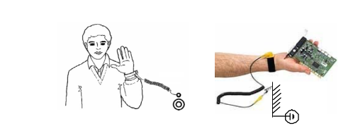
WARNING! The printed circuit boards contain components sensitive to electrostatic discharge. Wear a grounding wrist band when handling the boards. Do not touch the boards unnecessarily
Use grounding strip:
WARNING! Handle the fiber optic cables with care. When unplugging optic cables, always grab the connector, not the
cable itself. Do not touch the ends of the fibers with bare hands as the fiber is extremely sensitive to dirt. The minimum
allowed bend radius is 35 mm (1.4 in.).
Mechanical installation
These notes are intended for all who install the drive. Handle the unit carefully to avoid damage and injury.
WARNING!
• DCS800 sizes D4 ... D7: The drive is heavy. Do not lift it alone. Do not lift the unit by the front cover. Place units D4, D4+ and D5 only on their back. DCS800 sizes D5 ... D7: The drive is heavy. Lift the drive by the lifting lugs only. Do not tilt the unit. The unit will overturn from a tilt of about 6 degrees.
-
 AEROTECH SM Series High-Performance Stepper Motors
 -
 AEROTECH BLMSC Series Linear Motors
 -
 AEROTECH Custom Linear Motors
 -
 AEROTECH BMS Series Brushless, Slotless Rotary Motors
 -
 AEROTECH BM Series Brushless Rotary Motors
 -
 AEROTECH BLMX Series Linear Motors
 -
 AEROTECH BLMH Series Linear Motors
 -
 AEROTECH BLM Series Linear Motors
 -
 AEROTECH BLMC Series Linear Motors
 -
 AEROTECH BLMUC-143 Linear motor forcer with thermistor
 -
AEROTECH BLMUC-111 Linear motor forcer with thermistor
-
AEROTECH BLMUC-95 Linear motor forcer with thermistor
-
AEROTECH BLMUC-79 Linear motor forcer with thermistor
-
AEROTECH BLMUC Series Linear Motors
-
 AEROTECH Automation1 FLEX Distributed Amplifier Multi-Axis Servo Control System
 -
 AEROTECH Automation1 HXA4 6-Axis Hexapod Servo Drive
 -
 AEROTECH Automation1 iHXA4 6-Axis Hexapod Servo Drive with Motion Controller
 -
 AEROTECH Modular System Control Console
 -
 AEROTECH TV Series Transformers
 -
 AEROTECH TM Series Transformers
 -
 AEROTECH UFM Noise Filter Module
 -
 AEROTECH MFM Motor Filter Module
 -
 AEROTECH MPG Handwheel Pendant
 -
 AEROTECH Automation1 Multi-Axis Joystick
 -
 AEROTECH ETM Enhanced Throughput Module
 -
 AEROTECH Automation1 XL4s High-Speed, Single-Phase Linear Servo Drive
 -
 AEROTECH Automation1 XL2e Enhanced, Compact Linear Servo Drive
 -
 Automation1 iXL2e Enhanced, Compact Linear Servo Drive with Motion Controller
 -
 AEROTECH Automation1 XL5e Enhanced, Linear Servo Drive
 -
 AEROTECH Automation1 iXL5e Enhanced Linear Servo Drive with Motion Controller
 -
 AEROTECH Automation1 GI4 Laser Scan Head Controller
 -
 AEROTECH Automation1 SI4 Stepper Interface
 -
AEROTECH Automation1 XI4 Servo Interface
-
 AEROTECH AEROTECH Automation1 iXI4 Servo Interface with Motion Controller
 -
 AEROTECH Automation1 XC6e Enhanced, High-Power PWM Servo Drive
 -
 AEROTECH Automation1 iXC6e Enhanced, High-Power PWM Servo Drive with Motion Controller
 -
 AEROTECH Automation1 XC2 Compact PWM Servo Drive
 -
 AEROTECH Automation1 XC4 PWM Servo Drive
 -
 AEROTECH Automation1 GL4 Galvo Laser Scan Head Linear Drive
 -
 AEROTECH Automation1 XC2e Enhanced, Compact Servo Drive with PWM+
 -
 AEROTECH Automation1 XC4e Enhanced, PWM Servo Drive
 -
 AEROTECH Automation1 XR3 Multi-Axis Servo Drive Rack
 -
 AEROTECH Automation1 iXR3 Multi-Axis Servo Drive Rack with Motion Controller
 -
 AEROTECH Automation1 iXC2 Compact PWM Servo Drive with Motion Controller
 -
 AEROTECH Automation1 iXC2e Enhanced, Compact PWM+ Servo Drive with Motion Controller
 -
 AEROTECH Automation1 iXC4 PWM Servo Drive with Motion Controller
 -
 AEROTECH Automation1 iXC4e Enhanced, PWM Servo Drive with Motion Controller
 -
 AEROTECH Automation1 iPC Industrial PC with Motion Controller
 -
 AEROTECH EPICS & TANGO Drivers for Distributed Control Systems
 -
 AEROTECH .NET, C, Python & LabVIEW APIs Custom Application Develotpmen
 -
 AEROTECH Automation1 Industrial Ethernet Support
 -
 AEROTECH Automation1 iSMC Intelligent, Software-Based Motion Controller
 -
 AEROTECH Automation1 iXA4 1- 2- or 4-Axis PWM Servo Drive with Motion Controller
 -
 AEROTECH Automation1 XA4 1- 2- or 4-Axis PWM Servo Drive
 -
 CTI 2500-ADP2-DISC Discrete Wiring Adapter for Series 500
 -
 CTI 2500-ADP1 Analog Wiring Adapter for Series 500
 -
 CTI 2500C-RADP-RS485 Remote Base Controller Adapter for Series 500
 -
 CTI 2500C-RADP-RBC Profibus RBC Adapter for Series 500
 -
 CTI 2500C-PADP-120V 120VAC 50W Power Supply for Series 500
 -
 CTI 2500-RADP RBC Adapter for Series 500
 -
 CTI 2500-R4500 520/530/DBC Adapter for Series 500 - MATURE
 -
 CTI 2500-PADP Power Supply Adapter for Series 500
 -
 CTI 2500-IADP I/O Adapter for Series 500
 -
 CTI 2500-VP15A-N4-W7 15" Flat-Panel PC with Windows® 7 Embedded
 -
 CTI 2500S-27-1750 Slice I/O, Ethernet, RS232/485. 900MHz, 2DIO / 4UAI / 2AI
 -
 CTI 2500S-26-1750 Slice I/O, Ethernet, RS232/485. 900MHz, 8DIO / 2UAI
 -
 CTI 2500S-23-1750 Slice I/O, Ethernet, RS232/485. 900MHz, 4DI / 4DO / 2UAI / 2AO
 -
 CTI 2500S-27-1550 Slice I/O, RS232/485. 2DIO / 4UAI / 2AI
 -
 CTI 2500S-26-1550 Slice I/O, RS232/485. 8DIO / 2UAI
 -
 CTI 2500S-23-1550 Slice I/O, RS232/485. 4DI / 4DO / 2UAI / 2AO
 -
 CTI 2500S-27-1050 Slice I/O, Ethernet, 2DIO / 4UAI / 2AI
 -
 CTI 2500S-26-1050 Slice I/O, Ethernet, 8DIO / 2UAI
 -
 CTI 2500S-23-1050 Slice I/O, Ethernet, 4DI / 4DO / 2UAI / 2AO
 -
 CTI 2500C-32F-CJC 32-Pin Field Wiring Connector with Cold Junction Compensation
 -
 CTI 2500C-32F 32-Pin Field Wiring Connector
 -
 CTI 2500C-8-TC Eight Thermocouple Inputs
 -
 CTI 2500C-8-RTD Eight RTD Inputs
 -
 CTI 2500C-8-RL-FC 8 Form-C Relay Outputs
 -
 CTI 2500C-8-IDO-24V 8 Isolated 24VDC Outputs
 -
 CTI 2500C-8-IDO-120V 8 Isolated 120VAC Outputs
 -
 CTI 2500C-16-DO-24V Sixteen 24VDC Digital Outputs
 -
 CTI 2500C-16-DO-120V Sixteen 120VAC Digital Outputs
 -
.png) CTI 500C-16-IDI-24V Sixteen Isolated 24V AC/DC Digital Inputs
CTI 500C-16-IDI-24V Sixteen Isolated 24V AC/DC Digital Inputs -
 CTI 2500C-16-IDI-120V Sixteen Isolated 120V AC/DC Digital Inputs
 -
 CTI 2500C-16-DIDO-SIM Sixteen Digital Input and Output SImulator
 -
 CTI 2500C-16-DI-24V Sixteen 24V AC/DC Digital Inputs
 -
 CTI 2500C-16-DI-120V Sixteen 120V AC/DC Digital Inputs
 -
 CTI 2500C-RBC-RS485 RS485 Remote Base Controller
 -
 CTI 2500C-RBC-PRF Profibus Remote Base Controller
 -
 CTI 2500C-PS-24V-35 35-Watt DC Power Supply
 -
 CTI 2500C-PS-120V-35 35-Watt AC Power Supply
 -
 CTI 2500C-R8 Eight-Slot Base
 -
 CTI 2500C-R4 Four-Slot Base
 -
 CTI 2500C-R16 Sixteen-Slot Base
 -
 CTI 2500C-2572-B Fast Ethernet TCP/IP Adapter
 -
 CTI 2500C-J750 Compact Janus PAC with 3MB Project Memory
 -
 CTI 2500C-C300 CPU with 512K User Memory
 -
 CTI 2500C-C200 CPU with 256K User Memory
 -
 CTI 2500C-C100 CPU with 128K User Memory
 -
 CTI 2500C-8-AO 8 Analog Outputs
 -
 CTI 2500C-8-AI 8 Analog Inputs
 -
 CTI 2559-FCAL Precision Calibration Connector
 -
 CTI 2559-FPC 40-Position Screw-Terminal Connector
 -
 CTI 2500-RFC PLC to RF Modem Cable
 -
 CTI 2500-40F 40-Position Standard Screw-Terminal Connector
 -
 CTI 2505 Vibration Sensor Interface Module
 -
 CTI 2554-A 4-Channel Isolated High Speed Counter Module
 -
 CTI 2553-A 2-Channel Mag Meter Input Module
 -
 CTI 2502 2-Channel High Speed Counter Input Module
 -
 CTI 2559-TC 8-Channel Thermocouple Input Module
 -
 CTI 2556-A 16-Channel Isolated Thermocouple Input Module
 -
 CTI 2556 16-Channel Isolated Thermocouple Input Module
 -
 CTI 2551-A 8-Channel Isolated Thermocouple Input Module
 -
 CTI 2559-RTD 8-Channel RTD Input Module
 -
 CTI 2557-A 16-Channel RTD Input Module
 -
 CTI 2557 16-Channel RTD Input Module
 -
 CTI 2552-A 8-Channel Isolated RTD Input Module
 -
 CTI 2534 8-Point Form-C Relay Output Module
 -
 CTI 2532 16-Point Form-A Relay Output Module
 -
 CTI 2531 32-Point Form-A Relay Output Module
 -
 CTI 2530 8-Point Form-C Relay Output Module
 -
 CTI 2562 8-Channel Analog Output Module
 -
 CTI 2560-A 8-Channel Isolated Analog Output Module
 -
 CTI 2501 8in/4out Analog Module
 -
 CTI 2558 8-Channel Analog Input Module
 -
 CTI 2555-A 16-Channel Analog Input Module
 -
 CTI 2550-A 8-Channel Isolated Analog Input Module
 -
 CTI 2599 8/16/32-Point AC Output Module


