
ABB DCS800 Drives
Safety instructions
What this chapter contains
This chapter contains the safety instructions which you must follow when installing,
operating and servicing the drive. If ignored, physical injury or death may follow, or
damage may occur to the drive, the motor or driven equipment. Read the safety instructions
before you work on the unit.
To which products this chapter applies
The information is valid for the whole range of the product DCS800, the converter modules DCS800-S0x size D1 to D7, field exciter units DCF80x, etc. like the Rebuild Kit DCS800-R00-9xxx.
Use of warnings and notes
There are two types of safety instructions throughout this manual: warnings and notes. Warnings caution you about conditions which can result in serious injury or death and/or damage to the equipment. They also tell you how to avoid the danger. Notes draw attention to a particular condition or fact, or give information on a subject. The warning symbols are used as follows:
Dangerous voltage warning warns of high voltage which can cause physical injury and/or damage to the equipment. General danger warning warns about conditions, other than those caused by electricity, which can result in physical injury or death and/or damage to the equipment. Electrostatic sensitive discharge warning warns of electrostatic discharge which can damage the equipment.
Installation and maintenance work
These warnings are intended for all who work on the drive, motor cable or motor. Ignoring the instructions can cause physical injury or death and/or damage to the equipment..
• Only qualified electricians are allowed to install and maintain the drive!
• Never work on the drive, motor cable or motor when main power is applied. Always ensure by measuring with a multimeter (impedance at least 1 Mohm) that: 1. Voltage between drive input phases U1, V1 and W1 and the frame is close to 0 V. 2. Voltage between terminals C+ and D- and the frame is close to 0 V.
• Do not work on the control cables when power is applied to the drive or to the external control circuits. Externally supplied control circuits may cause dangerous voltages inside the drive even when the main power on the drive is switched off. • Do not make any insulation resistance or voltage withstand tests on the drive or drive modules.
• Isolate the motor cables from the drive when testing the insulation resistance or voltage withstand of the cables or the motor.
• When reconnecting the motor cable, always check that the C+ and D- cables are connected with the proper terminal. Note:
• The motor cable terminals on the drive are at a dangerously high voltage when the main power is on, regardless of whether the motor is running or not.
• Depending on the external wiring, dangerous voltages (115 V, 220 V or 230 V) may be present on the relay outputs of the drive system (e.g. SDCS-IOB-2 and RDIO).
• DCS800 with enclosure extension: Before working on the drive, isolate the whole drive from the supply
These instructions are intended for all who are responsible for the grounding of the drive. Incorrect grounding can cause physical injury, death and/or equipment malfunction and increase electromagnetic interference.
WARNING!
• Ground the drive, motor and adjoining equipment to ensure personnel safety in all circumstances, and to reduce electromagnetic emission and pick-up.
• Make sure that grounding conductors are adequately sized and marked as required by safety regulations. • In a multiple-drive installation, connect each drive separately to protective earth (PE ).
• Minimize EMC emission and make a 360° high frequency grounding (e.g. conductive sleeves) of screened cable entries at the cabinet lead-through plate.
• Do not install a drive equipped with an EMC filter to an ungrounded power system or a high resistance-grounded (over 30 ohms) power system. Note:
• Power cable shields are suitable as equipment grounding conductors only when adequately sized to meet safety regulations.
• As the normal leakage current of the drive is higher than 3.5 mA AC or 10 mA DC (stated by EN 50178, 5.2.11.1), a fixed protective earth connection is required.
Printed circuit boards and fiber optic cables
These instructions are intended for all who handle the circuit boards and fiber optic
cables. Ignoring the following instructions can cause damage to the equipment.
WARNING! The printed circuit boards contain components sensitive to electrostatic discharge. Wear a grounding wrist band when handling the boards. Do not touch the boards unnecessarily
Use grounding strip:

WARNING! Handle the fiber optic cables with care. When unplugging optic cables, always grab the connector, not the
cable itself. Do not touch the ends of the fibers with bare hands as the fiber is extremely sensitive to dirt. The minimum
allowed bend radius is 35 mm (1.4 in.).
Mechanical installation
These notes are intended for all who install the drive. Handle the unit carefully to
avoid damage and injury.
WARNING!
• DCS800 sizes D4 ... D7: The drive is heavy. Do not lift it alone. Do not lift the unit by the front cover. Place units D4, D4+ and D5 only on their back. DCS800 sizes D5 ... D7: The drive is heavy. Lift the drive by the lifting lugs only. Do not tilt the unit. The unit will overturn from a tilt of about 6 degrees.
• Make sure that dust from drilling does not enter the drive when installing. Electrically conductive dust inside the unit may cause damage or lead to malfunction.
• Ensure sufficient cooling.
• Do not fasten the drive by riveting or welding.
These warnings are intended for all who plan the operation of the drive or operate the drive. Ignoring the instructions can cause physical injury or death and/or damage to the equipment.
• Before adjusting the drive and putting it into service, make sure that the motor and all driven equipment are suitable for operation throughout the speed range provided by the drive. The drive can be adjusted to operate the motor at speeds above and below the base speed.
• Do not control the motor with the disconnecting device (disconnecting mains); instead, use the control panel keys and , or commands via the I/O board of the drive.
• Mains connection You can use a disconnect switch (with fuses) to disconnect the electrical components of the drive from the mains for installation and maintenance work. The type of disconnect switch used must be as per EN 60947-3, Class B, so as to comply with EU regulations, or a circuit-breaker type which switches off the load circuit by means of an auxiliary contact causing the breaker's main contacts to open. The mains disconnect must be locked in its "OPEN" position during any installation and maintenance work.
• EMERGENCY STOP buttons must be installed at each control desk and at all other control panels requiring an emergency stop function. Pressing the STOP button on the control panel of the drive will neither cause an emergency stop of the motor, nor will the drive be disconnected from any dangerous potential. To avoid unintentional operating states, or to shut the unit down in case of any imminent danger according to the standards in the safety instructions it is not sufficient to merely shut down the drive via signals "RUN", "drive OFF" or "Emergency Stop" respectively "control panel" or "PC tool".
• Intended use The operating instructions cannot take into consideration every possible case of configuration, operation or maintenance. Thus, they mainly give such advice only, which is required by qualified personnel for normal operation of the machines and devices in industrial installations. If in special cases the electrical machines and devices are in-tended for use in non-industrial installations - which may require stricter safety regulations (e.g. protection against contact by children or similar) - these additional safety measures for the installation must be provided by the customer during assembly. Note:
• When the control location is not set to Local (L not shown in the status row of the display), the stop key on the control panel will not stop the drive. To stop the drive using the control panel, press the LOC/REM key and then the stop key .
Chapter overview
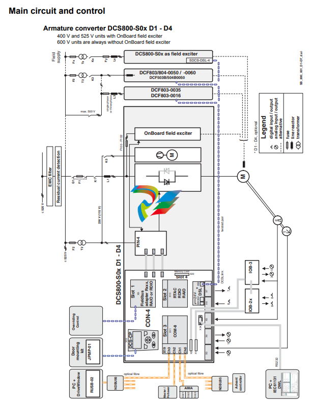
This chapter describes briefly the operating principle and construction of the
converter modules in short.
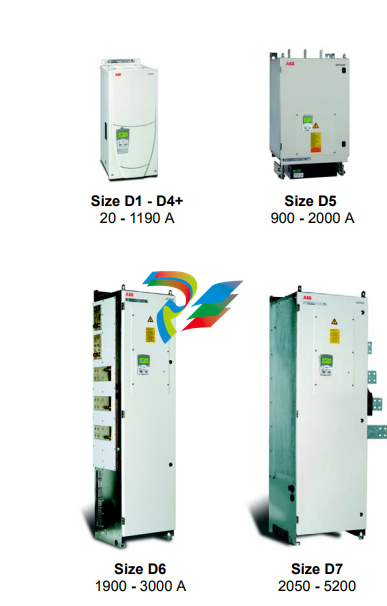
The DCS800
The DCS800-S size D1 - D7 are intended for controlling DC motors.
Mechanical installation
Chapter overview This chapter describes the mechanical installation of the DCS800.
Unpacking the unit
• Open the box,
• take out shock dampers,
• separate manual and accessories.Attention: Do not lift the drive by the cover!
Delivery check
Check that there are no signs of damage. Before attempting installation and
operation, check the information on the nameplate of the converter module to verify
that the unit is of the correct type. The label includes an IEC rating, cULus, C-tick
(N713) and CE markings, a type code and a serial number, which allow individual
identification of each unit. The remaining digits complete the serial number so that
there are no two units with the same serial number.
See an example nameplate below
Before installation
Install the drive in an upright position with the cooling section facing a wall. Check the installation site according to the requirements below. Refer to chapter Dimensions and weights for frame details. Requirements for the installation site See chapter Technical data for the allowed operation conditions of the drive. Wall The wall should be as close to vertical as possible, of non-flammable material and strong enough to carry the weight of the unit. Check that there is nothing on the wall to inhibit the installation. Floor The floor or material below the installation should be non-flammable. Free space around the unit Around the unit free space is required to enable cooling airflow, service and maintenance see chapter Dimensions and weights.
Cabinet installation.
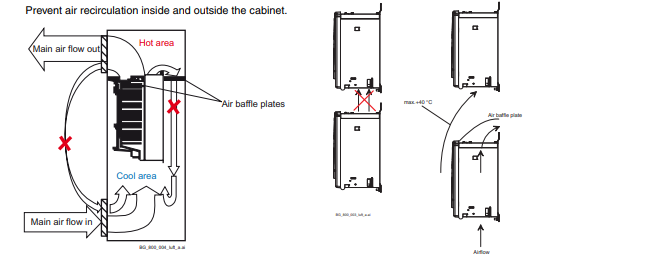
The required distance between parallel units is five millimetres (0.2 in.) in installations without the front cover. The cooling air entering the unit must not exceed +40 °C (+104 °F).
Preventing cooling air recirculation Unit above another
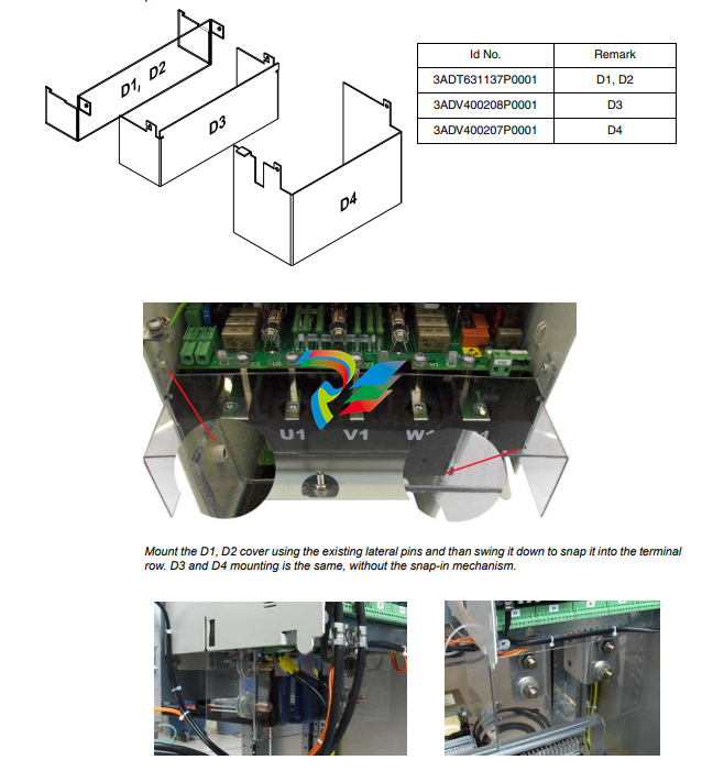
Terminal cover according to VBG 4 regulations For converter modules size D1 - D4 shrouds for protection against contact are provided.
Connecting the external control unit of a D7 module (+P906)
During installation the SDCS-CON-4 needs to be connected with the SDCS-PIN-51 using two shielded 16 pole flat cables. These cables connect terminals X12 with each other, as well as terminals X13. For easier access to the terminals in the control unit, connecting boards SDCS-CCB-4 or SDCS-CCB-5 are placed close to the lower end of the metal frame. When connecting X12 and X13 make sure the flat cables are marked at both ends, one with X12, the other with X13. Worst case put stickers on! Wedge the blank screen of the flat cable in position using the screen clamp, then place the plug into its socket.
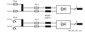
Fuses F3.2 and F3.3 are used as line protectors and cannot protect the field supply unit. Only pure HRC fuses or miniature circuit-breakers must be used. Semiconductor fuses will be tripped, for example, by the transformer’s inrush current.
Semiconductor fuses (F1) and fuse holders for armature circuit The converters are subdivided into two groups:
• Unit sizes D1, D2, D3 and D4 with rated currents up to 1000 A require external fuses.
• In unit sizes D4+, D5, D6 and D7 with rated currents from 900 A to 5200 A, branch fuses are internally installed (no additional external AC or DC fuses are needed). The fourth column of the table below assigns the AC fuse to the unit. In case the converter should be equipped with DC fuses, use the same type of fuse as on the AC side
EMC filters (E1) Filter in a grounded line (earthed TN or TT network) The filters are suitable for grounded lines only, for example in public European 400 VAC lines. According to EN 61800-3 filters are not needed in insulated industrial networks with own supply transformers. Furthermore they could cause safety risks in such floating lines (IT networks). According to EN 61800-3 filters are not needed in industrial zone (Second Environment) for DCS800 drives above 100 ADC rated current. For rated currents below 100 ADC the filter requirement is identical to Light Industry (First Environment). Three-phase filters EMC filters are necessary to fulfil the standard for emitted interference if a converter shall be run at a public low voltage line, in Europe for example with 400 VAC. Such lines have a grounded neutral conductor. ABB offers suitable three-phase filters for 400 VAC. For 440 VAC public low voltage lines outside Europe 500 VAC filters are available. Optimize the filters for the real motor currents: IFilter = 0.8 • IMOT max; the factor 0.8 respects the current ripple. Lines with 500 VAC up to 1000 VAC are not public. There are local networks inside factories, and they do not supply sensitive electronics. Therefore converters do not need EMC filters if they shall run with 500 VAC and more.
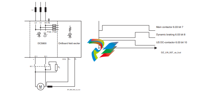
Converters size D4+ - D7 configuration using external field exciters DCF803, DCF804 Wiring the drive according to this diagram offers the highest degree of monitoring functions done by the drive. Field converters DCF803 / DCF804 are equipped with their own synchronization and must be supplied from independent mains supply voltage max. 500 V (single-phase or 3-phase).
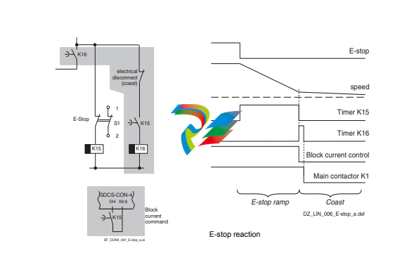
Start, Stop and E-Stop control The relay logic is splitted into four parts: 1: Generation of the On / Off and Start / Stop command: The commands represented by K20 and K21 (latching interface relay) can also be generated by a PLC and transferred to the terminals of the converter either by relays, using galvanic isolation or directly via 24 V signals. There is no need to use hardwired signals. Transfer these commands via serial communication. Even a mixed solution can be realized by selecting different possibilities for the one or the other signal (see parameter group 11). 2: Generation of control and monitoring signals: Control the main contactor K1 for the armature circuit by the dry contact of DO8 located on the SDCS-PIN-4 or SDCS-POW-4. The status of motor (K6) and converter (K8) fans can be monitored by means of MotFanAck (10.06) and ConvFanAck (10.20). 3: Off2 (Coast Stop) and Off3 (E-stop): Beside On / Off and Start / Stop the drive is equipped with two additional stop functions Off2 (Coast Stop) and Off3 (E-stop) according to Profibus standard. Off3 (E-stop) is scalable via E StopMode (21.04) to perform stop category 1. Connect this function to the E-stop push button without any time delay. In case of E StopMode (21.04) = RampStop the K15 timer relay must be set longer than E StopRamp (22.04). For E StopMode (21.04) = Coast the drive opens the main contactor immediately. Off2 (Coast Stop) switches the DC current off as fast as possible and prepares the drive to open the main contactor or drop the mains supply. For a normal DC motor load the time to force the DC current to zero is below 20 ms. This function should be connected to all signals and safety functions opening the main contactor. This function is important for 4-Q drives. Do not open main contactor during regenerative current. The correct sequence is: 1. switch off regenerative current 2. then open the main contactor In case the E-stop push button is hit, the information is transferred to the converter via DI5. In case E StopMode (21.04) = RampStop or TorqueLimit the converter will decelerate the motor and then open the main contactor. If the drive has not finished the function within the K15 timer setting, the drive must get the command to switch off the current via K16. After the K16 timer has elapsed, the main contactor is opened immediately, independent of the drive's status.
-
 Beckhoff Polaris CP7011-1002-0010 operator operator HMI display 30.5 cm
 -
 Beckhoff AM8052-0JH1-0000 Servomotor 10.7 Nm (M0), F5 (104 mm)
 -
 Beckhoff BX5100-0000 CANopen Bus Terminal Controller
 -
 Beckhoff CX9020-0115 PLC Module CX90200115
 -
 Beckhoff module EJ7211-0010 EtherCAT plug-in module
 -
 BECKHOFF AX5203-0000 Servo Driver
 -
 BECKHOFF CP6201-0001-0020 24VDC UNMP
 -
 Beckhoff CX5120-0135 Embedded PC CPU Module
 -
 BECKHOFF C5240-0020/000224115 Plc Module
 -
 Beckhoff CP2918-0000 nelCP29xx-0000Pa | Multi-touch built-in Control Panel with DVI/USB Extended interface
 -
 Beckhoff CX2020-0122 Embedded PC Controller
 -
 Beckhoff C6640-0040 Control Cabinet Industrial PC 7-Slot
 -
 BECKHOFF CONTROL CABINET INDUSTRIAL PC - C6930-1062-0050
 -
 Beckhoff Automation EtherCAT Terminal EK1100 EK1122
 -
Beckhoff CP6533-0001-0060 IPC
-
 Beckhoff EK9500 | EtherNet/IP™ Bus Coupler
 -
 Beckhoff CP6202-1047-0050 - An industrial-grade embedded panel computer.
 -
 Beckhoff C6650-0040 Industrial PC
 -
 BECKHOFF CX5230-0185 / 000119805 PLC Module
 -
 BECKHOFF EL4732 | EtherCAT Terminal, 2-channel analog output, voltage, ±10 V, 16 bit, oversampling
 -
 Beckhoff CP6202-0001-0010 Economy Built-In Panel
 -
 Beckhoff AX5206-0000-0202 Digital Compact Servo Drives 2-channel
 -
 Beckhoff CP6606-0001-0020 7-inch Economy Panel PC
 -
 Beckhoff CPU basic module CX2020-0155 + power supply module CX2100-0004
 -
 Beckhoff CP2913-000 Multi-Touch Display
 -
 Beckhoff CP6500-1012-0060 14250369 Control Cabinet
 -
 Beckhoff CP7902-0001-0000 Economy Control Panel with DVI/USB Extended interface
 -
 Beckhoff C6920-0010 Control cabinet Industrial PC
 -
 BECKHOFF C3640-0050 Build-in Industrial PCs
 -
 Beckhoff KL6023-0000 KL6023 EnOcean Wireless-Adapter
 -
 Kollmorgen AKM54G-ANC2DB00 servo motor
 -
 Kollmorgen AKD-P00606-NBCN-0000 Servo Drive
 -
Kollmorgen S200 Series S20350-VTS SERVO DRIVE
-
 KOLLMORGEN AKD-P00606-NBCC-I000 SERVO DRIVE
 -
 Kollmorgen MV65WKS-CE310/22PB Servo Drive Control Module
 -
 Kollmorgen S20360-VTS-021 Servo Drive
 -
 KOLLMORGEN CR06550 High-precision digital servo amplifier
 -
 KOLLMORGEN DBL5N01050-03S-VV0-S40 3-Phase AC Synchronous Brushless Servo Motor
 -
 KOLLMORGEN S70301-NANANA-024 SERVO DRIVE
 -
 Kollmorgen S20360-VTS S200 Series Servo Drive
 -
 Kollmorgen RBE-03011-A00 Brushless Frameless Servo Motor
 -
 KOLLMORGEN AKD-T00306-NBAN-0000 INPUT SERVO DRIVE
 -
 KOLLMORGEN S700 Servo Controller S70302-NANANA
 -
 Kollmorgen AKD-P00607-NBEC-0000 400/480VAC 4.40KVA Servo Drive.
 -
 KOLLMORGEN S70102-NANANA SERVO DRIVE
 -
 KOLLMORGEN AKM21E-ANSNEH02 PM Servo Motor & PRD-AMPE25EB-00 Servo Drive Array
 -
 KollMorgen SC1R06260 Servo Drive 1.4/2.2 KVA 115230 Vac
 -
 Kollmorgen AKD-P00306-NBAN-0000 Servo Drive
 -
Kollmorgen TTB2-2042-3052-A DC Motor Industrial Drive 5.5A 185 oz/in
-
 KOLLMORGEN SERVOSTAR 610-AS SERVO AMPLIFIER_SERVOSTAR610AS_S61001
 -
 KOLLMORGEN PRD-0016400P-10 & PRD-0016600D-30 Axis Control System Modules
 -
KOLLMORGEN Seidel DBL5N01700-03S-000-S40 Servo Motor
-
 Hirschmann RS20-1600M2T1SDAEHH03.1.02 Rail Switch
 -
 Hirschmann BRS30-24TX Industrial Rail Switch
 -
 Hirschmann RSPM20-4T14T1EV9HHS999.9.99 Managed Ethernet Switch
 -
 Hirschmann BELDEN RS40-0009CCCCSDAPHH09.0.14 / RS400009CCCCSDAPHH09014
 -
Hirschmann RS40 Rail Switch RS40-0009CCCCSDAE
-
 Hirschmann BELDEN RS30-0802T1T1SDAP / RS300802T1T1SDAP Fully Managed Layer 2 Compact Rail Switch
 -
 Hirschmann BELDEN RS20-0800M2M2SDAUHH / RS200800M2M2SDAUHH
 -
 Hirschmann EAGLE30-04022O6TT999SCCY9HSE3F Industrial Firewall Router Switch
 -
 Hirschmann RS20-1600T1T1SDAEHH09.0.14 RS20 Rail Mount Ethernet Switch
 -
 Hirschmann EAGLE0200T1T1TDDY90000HHE05.3.03 Industrial Security Router
 -
Hirschmann - BELDEN MIPP-AD-1L9P
-
 HIRSCHMANN RSPM20-4Z64Z6TV9HHS9 942 106-999 RAIL SAFETY SWITCH
 -
 HIRSCHMANN FIBEROPTIC MODULE FIP P/N: OZDFIPG3T
 -
 HIRSCHMANN RS20-1600M2M2SDAUHH Ethernet rack-mounted switch
 -
 HIRSCHMANN BELDEN RS20-0400T1T1SDAEHH04.0.01 / RS200400T1T1SDAEHH04001
 -
HIRSCHMANN MM2-4FXM3 MICE Media Module
-
HIRSCHMANN RS20-0800M2M2SDAE Industrial Ethernet Rail Switch
-
 Hirschmann RS20-2400T1T1SDAP / RS20-2400T1T1SDAPHH05.0.02
 -
 GE MLJ1005B010H00C MLJ Digital Synchromism Check
 -
 ALSTOM MICROTECH DX21-M2 Digital Excitation Controller
 -
HIRSCHMANN BRS20-1200ZZZZ-STCY99HHSES
-
 HIRSCHMANN MM3-4FXM2 MICE Media Module
 -
Hirschmann RSB20-0800T1T1SAABHH 8Port ENet Rail Switch RSB20
-
 Hirschmann MACH102-8TP Ethernet Switch
 -
 SAACKE DDZ-M marine steam pressure atomizer
 -
 SAACKE SKV-A marine rotary cup atomizer
 -
 SAACKE Seavis HMI05e
 -
 Kollmorgen MMC-SD-2.0-230 Servo Drive 100-240VAC 2KW 10A Output 3PH 100-240VAC
 -
 Kollmorgen Servo drive CR10550
 -
 Kollmorgen AKD-P01207-NACN-0054 Servo Driver
 -
 Kollmorgen S406M-CA-036 Servostar
 -
.png) Kollmorgen AKD-B02407-NAAN-0000 Digital Servo Drive
Kollmorgen AKD-B02407-NAAN-0000 Digital Servo Drive -
 Kollmorgen SERVOSTAR S406AM-CA Digital Servo Drive
 -
 KOLLMORGEN SERVOSTAR 603-AS SERVO AMPLIFIER_SERVOSTAR603AS_S60301
 -
Kollmorgen S700 Servo Controller (S70602-NANANA-NA)
-
 Kollmorgen MPK411 controller
 -
 KOLLMORGEN MMC-SD-1.3-460-D Smart Drive
 -
 KOLLMORGEN AKM21C-CKB2AA-00 / AKM21CCKB2AA00 Servomotor
 -
 BECKHOFF AX5106-0000-0200 | Digital Compact Servo Drives 1-channel
 -
 BECKHOFF C3620-0000 INDUSTRIAL COMPUTER (MOTORSHELVES)
 -
 Beckhoff EK1960-0000 TwinSAFE Compact Controller
 -
 Beckhoff C6930-0050 Control Cabinet Industrial PC
 -
 Beckhoff CP7711-0001-0030 Industrial Computer Detection
 -
 Beckhoff CX1001-0111 Embedded PC CPU Module
 -
 Beckhoff C6017-0020 | Ultra-compact Industrial PC
 -
 Beckhoff EK1322 | 2-port EtherCAT P junction with feed-in
 -
 Beckhoff CP2219-0010 Panel
 -
 BECKHOFF C6015-0020 ULTRA COMPACT INDUSTRIAL PC
 -
 BECKHOFF CX2030-0120/Standard CPU Module Embedded PC Windows PLC controller
 -
 Beckhoff CP7721-1090-0020 Panel PC
 -
 Beckhoff PC CPU Module CX5130-0175
 -
 Beckhoff C6920-0050 Control Cabinet
 -
 Beckhoff EL6631 EtherCAT 2-Port Communication Interface, Profinet RT Controller
 -
 Beckhoff CP6202-0001-0060 touch screen panel PC
 -
 Beckhoff CP3916-1002-0000 Multi-Touch Control Panel
 -
 Beckhoff EP1809-0021 | EtherCAT Box, 16-channel digital input, 24 V DC, 3 ms, M8Preferred type
 -
 Beckhoff CX8190 PLC Embedded Industrial PC Ethernet Controller
 -
 Beckhoff CX2100-0914 Power Supply for External
 -
 Beckhoff Automation CP6906-0001-0000 HMI
 -
 Beckhoff EP7342-0002 Module
 -
 Beckhoff CX1020-0112 / CX1100-0910 / CX1020-N010 / CX1100-0003 Windows CPU
 -
 Beckhoff EP7211-0034 EtherCAT Box 1 Channel Motion Interface
 -
 Beckhoff C6240-0030 Control cabinet Industrial PC
 -
 beckhoff motherboard CB1052-0004 CB1052-0004
 -
 Beckhoff AX2006-AS Servo Drive / Variable Frequency Drive
 -
BECKHOFF CP6207-0001-0020 NSMP
-
 Beckhoff C6930-1142-0060 Industrial Computer
 -
 Beckhoff FC7501-0000 interface card
 -
 Beckhoff CX5140-0175 Embedded PC PLC CPU CX5140 Industrial Controller
 -
 Beckhoff CP7802-1100-0010: High-End IP65 Control Panel with DVI/USB Extended Interface
 -
BECKHOFF CP3716-1058-0010 CONTROL PANEL
-
 Beckhoff AX8108-0000 Single-Axis Module
 -
 Beckhoff CU8851-0000 | USB extension, USB Extended 2.0 receiver box
 -
Beckhoff C6017-0030 | Ultra-compact Industrial PC
-
 Beckhoff CX1001-0120/CX10010120.cx1000-n001.cx1000-n000 System Overview
 -
 Beckhoff CPU Module CX5140-0155/4GB CPU Module


