Summary of DCS800 TYRAK L Upgrade and Installation Manual

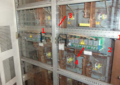
# Summary of DCS800 TYRAK L Upgrade and Installation Manual ## I. Product Positioning and Scope of Application The DCS800 Rebuild Kit for TYRAK L is an ABB DC drive upgrade kit specifically designed for TYRAK L DC drive systems with a current range of **950 A to 3000 A**. It is used to upgrade old TYRAK L drives to modern digital control systems. The kit is available in **2-Quadrant (2-Q)** and **4-Quadrant (4-Q)** versions, adapting to two large cabinet sizes of TYRAK L (950A~1400A and >1600A). By reusing existing components such as cabinets and power stacks, it achieves cost-effective upgrades while improving system reliability and communication capabilities. ## II. Safety Instructions 1. **Core Safety Requirements** - **High Voltage Protection**: Installation and maintenance must be performed by qualified electricians. After power-off, a multimeter (with impedance ≥1MΩ) must be used to confirm that the voltage between input phases, armature terminals, and the cabinet is close to 0V to avoid live operations . - **Grounding Specifications**: Drives, motors, and auxiliary equipment must be reliably grounded; grounding conductors must comply with safety standards. In multi-drive systems, each drive must be individually connected to protective earth (PE), and shielded cables must have 360° high-frequency grounding . - **Electrostatic Protection**: When handling printed circuit boards (e.g., SDCS-CON-4, SDCS-PIN-48), a grounding wristband must be worn, and a dedicated grounding strip (order number 3ADV050035P0001) should be used . - **Mechanical Safety**: Large drives (D4~D7) are heavy and require multiple people for handling; lifting by the front cover is prohibited. During installation, prevent drilling dust from entering the equipment and ensure sufficient heat dissipation . 2. **Operational Safety** - Emergency Stop: The "STOP" key on the control panel does not function as an emergency stop. Separate emergency stop buttons compliant with standards (e.g., DIN 57100) must be configured . - Power Disconnection: For maintenance, an isolating switch compliant with EN 60947-3 Class B must be used and locked in the "OPEN" position . ## III. Product Identification and Technical Data 1. **Model Identification** - TYRAK L drive models start with "YGMP" (single converter) or "YHMP" (double converter). For example, YGMP620-1400 indicates a single converter with a rated DC voltage of 620V and a rated current of 1400A . - Upgrade kit models: The 2-Q version is 3ADT220164R0001, and the 4-Q version is 3ADT220164R0002 . 2. **Technical Parameters** - **Environmental Conditions**: Operating temperature 0~55°C; storage temperature -40~70°C; humidity 5%~95% (non-condensing); current derating is required for altitudes >1000m (e.g., 50% current at 5000m) . - **Power Requirements**: Three-phase voltage 230~1000V (±10% continuous, ±15% short-term); frequency 50/60Hz (±2% static deviation) . - **Compliance**: Complies with EU Machinery Directive (98/37/EEC), Low Voltage Directive (73/23/EEC), and EMC Directive (89/336/EEC); UL certified (certificate No. E196914) for ≤600V systems in North America . ## IV. Hardware Composition ### Core Kit Components 1. **Pre-assembled Parts** - TYRAK L control cabinet door (without hinges, lock, and emergency stop button, which need to be reused from the old door). - Electronic housing (DCS800-R00-0000-00) containing control board SDCS-CON-4, power board SDCS-POW-4, drive interface board SDCS-DSL-4, and control panel . 2. **Loose Parts** - Measurement board SDCS-PIN-51, pulse transformer board SDCS-PIN-41A, and interface board SDCS-REB-1. - Cable set: The 2-Q version includes 1 20-core shielded flat cable (3m), 2 16-core shielded flat cables (5m), and 6 trigger wires; the 4-Q version includes 2 20-core cables, 2 16-core cables, and 12 trigger wires . 3. **Additional Mechanical Accessories** - Mounting brackets: Such as PIN48 mounting kit (3ADT783049R0001 for 4-Q high-current drives), DCF803 exciter mounting kit (3ADT783049R0003), and TYRAK L cabinet bracket (3ADT783052R0001), used to adapt to existing cabinet structures . ## V. Installation Steps ### Basic Process 1. **Cabinet Door Replacement** - Remove hinges, lock, and emergency stop button from the old door and install them on the new pre-assembled door; ensure the grounding cable of the lower hinge is reliably connected . - Connect the flat cable between the control board (SDCS-CON-4) and measurement board (SDCS-PIN-51); use metal clamps for shielding if the length exceeds 3m . 2. **Field Exciter Installation** - Select the mounting kit based on the exciter model: DCF803-0016 uses kit 3ADT783049R0003, DCF803-0035 uses kit 3ADT783050R0002, and DCF503-0050B can be directly installed on existing DIN rails or using TYRAK L brackets . 3. **Installation of Measurement and Trigger Boards** - The length of the trigger cable between SDCS-PIN-48 and thyristors must be <1m; 4-Q high-current drives (>1600A) require the PIN48 mounting kit (3ADT783049R0001) to fix the board in the middle of the power stack, ensuring reliable grounding . - SDCS-PIN-51 is recommended to be installed near SDCS-PIN-48 with a 3m cable between them; a SDCS-REB-2 relay board is required for longer distances . 4. **I/O Interface Modification** - Remove old I/O boards and install new I/O boards (SDCS-IOB-2x/3) using a custom card holder (3ADT783046R0001); drill holes in the aluminum rail for fixing and remove the rail during drilling to prevent metal debris from entering the equipment . ## VI. Communication Upgrade - **From Master-Field-Bus to DDCS**: Replace with the SDCS-COM-8 optical interface and use the PE1354B protocol converter to enable communication between MP200 and DCS800. MP200 must be reprogrammed to match the new data format . - **Hardware Support**: Up to 9 drives can be connected via the NDBU-95 branching unit, with a maximum fiber cable length of 30m (POF cable) or 200m (HCS cable) . ## VII. Appendix Key Points - **MP200 Upgrade Conditions**: Ensure MP200 spare parts are intact, application source code is available, and TYRAK has no uniquely customized software; upgrades require ABB professional engineers to debug communication drivers and DCS800 parameters . - **Kit Advantages**: Reuses existing power stacks, cabinets, and other components to reduce upgrade costs; supports IEC 61131-3 programming to enhance flexibility and functional expandability . Document version: 3ADW000416R0101 Rev A (April 2012). Technical parameters are subject to change. For further support, contact ABB regional centers.


