
ABB OTM_C_Summary of 21D Automatic Transfer Switch
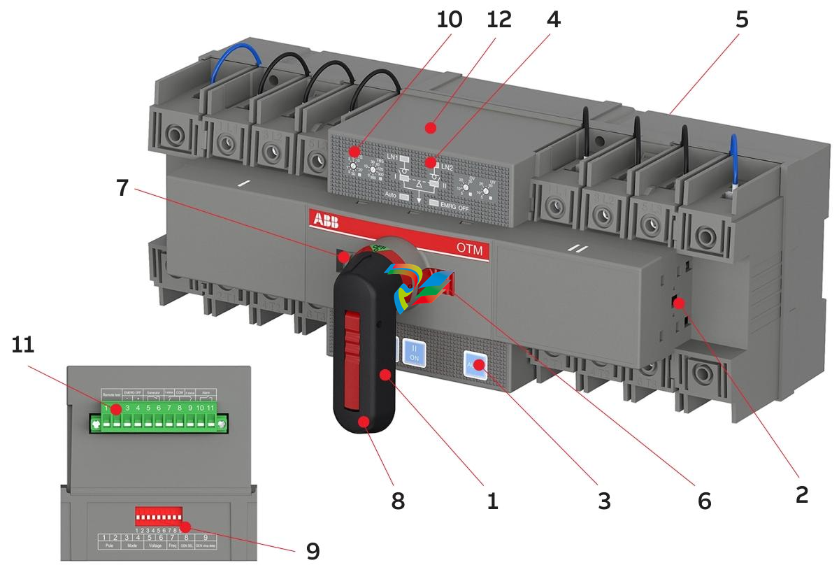
# Summary of ABB OTM_C_21D Automatic Transfer Switch ## I. Product Overview The OTM_C_21D is an automatic transfer switch launched by ABB, suitable for power source switching scenarios in three-phase or single-phase electrical networks. Its core functions include monitoring power abnormalities (no voltage, phase loss, overvoltage, undervoltage), enabling automatic/manual power switching, supporting generator start/stop control and remote testing, and achieving communication capabilities through an optional Modbus RTU module . The standard package includes an automatic transfer switch, an operating handle, a handle storage clip, a terminal plug, and an installation kit. It supports three operating modes: **Line 1 priority mode (default)**, no line priority mode, and manual return mode, meeting the power supply reliability requirements of different scenarios . ## II. Core Functions and Operating Modes ### 1. Switching Logic - **Line 1 Priority Mode**: Under normal conditions, Line 1 (primary power supply) is used. When an anomaly occurs on Line 1, it switches to Line 2 (backup power supply) after a transfer delay (Ts). When Line 1 recovers, it switches back to Line 1 after a return delay (TBs), and triggers a generator stop delay (Gs) simultaneously . - **No Line Priority Mode**: There is no priority between primary and backup power supplies. When an anomaly occurs on either line, it switches to the other line. It does not automatically return after the line recovers and only switches when the current line has an anomaly . - **Manual Return Mode**: It automatically switches to Line 2 when Line 1 is abnormal, but manual operation is required to return after Line 1 recovers, suitable for scenarios requiring manual confirmation . ### 2. Control Methods - **Manual Operation**: Inserting the handle automatically enters manual mode, disabling automatic switching. The switch can be toggled to positions I (Line 1), O (open), and II (Line 2) via the handle . - **Automatic Operation**: Pull out the handle and press the "AUTO" button; the LED lights up to indicate entry into automatic mode, with switching performed automatically according to preset logic . - **Testing Functions**: - **Local Test**: Manually trigger a switching cycle via the panel "I/O/II" buttons in automatic mode . - **Remote Test**: Short-circuit the remote test signal (≥100ms), and the switch simulates the switching process before returning to the initial position. The test can be canceled by pressing the "AUTO" button . ## III. Interfaces and Parameter Settings ### 1. Hardware Interfaces - **Buttons and Indicators**: Includes buttons "I (Line 1 closing)", "O (opening)", "II (Line 2 closing)", and "AUTO (automatic mode switching)"; LED indicators show power status (LN1/LN2), switch position (I/II), automatic mode (AUTO), and emergency stop (EMRG OFF) . - **Terminals**: There are 11 terminals in total, supporting remote test signal input, 24V DC emergency stop signal input, generator start/stop signal output, switch status feedback, and alarm signal output (dry contact, requiring external power supply) . - **DIP Switches and Knobs**: - 9-bit DIP switch: Sets the number of poles (2P/3P/4P), operating mode, rated voltage (220/380V, etc.), frequency (50/60Hz), generator enable, and stop delay (30s/240s) . - Rotary knobs: Adjust transfer delay (Ts: 0~30s), return delay (TBs: 0~900s), overvoltage threshold (OV: 5%~30%), and undervoltage threshold (UV: 5%~30%) . ### 2. Communication Function (Optional Modbus RTU Module) - **Parameters**: Address 1~32 (default 1), baud rate 4800~38400bps (default 9600bps), parity Even (default), stop bit 1 (default) . - **Function Codes**: Supports 03 (Read Holding Registers), 04 (Read Input Registers), 06 (Write Single Register), etc., enabling reading of switch status, voltage, alarm information, remote control of switching, and parameter configuration . - **Security Tips**: Firewalls, authentication measures, etc., need to be deployed to protect network communication; the Modbus protocol does not provide data encryption or authentication . ## IV. Technical Parameters and Installation ### 1. Technical Parameters | Item | Specification | |---------------------|-----------------------------------------------| | Rated Voltage | Single-phase 220~240V AC; Three-phase 380/400/415V AC | | Frequency | 50/60Hz | | Operating Voltage Range | 0.7~1.3 Ue | | Measurement Accuracy | ±3% | | Transfer Time | Total transfer time ≤2.5s, opening time 0.6~0.7s | | Output Relay Capacity | 3A AC1, 250V AC/24V DC | | Protection Class | IP20 (front panel) | | Operating Temperature | -25~55°C | | Altitude | Maximum 2000m | ### 2. Installation Requirements - **Installation Methods**: Supports screw fixing (M4 screws, torque 2Nm) or DIN rail mounting (requires locking clips to prevent falling off) . - **Dimensions**: 3-pole 233mm×130mm×95mm, 4-pole 286mm×130mm×95mm (length×width×height) . - **Wiring**: Terminals support a maximum of 70mm² wires, with up to 2 wires per terminal. Phase wires and neutral wires must be distinguished to avoid incorrect connection leading to faults . ## V. Maintenance and Troubleshooting ### 1. Maintenance Recommendations - Perform a switching test every 3 months to confirm that automatic/manual functions are normal . - Regularly check terminal connections, indicator lights, and mechanical component status, and clean dust . ### 2. Common Troubleshooting | Fault Phenomenon | Possible Cause | Solution | |-----------------------------------|-----------------------------------|-------------------------------------------| | LED not on despite normal power supply | Control unit not powered | Check and connect the power cord | | "AUTO" light not on or unresponsive | Handle not pulled out or electronic lock not released | Pull out the handle or remove the padlock, press "AUTO" to reset | | No automatic switching when power is abnormal | Not in automatic mode or dual power supplies faulty simultaneously | Confirm it is in automatic mode and troubleshoot power faults | | Emergency stop (EMRG OFF) function invalid | Signal not 24V DC or duration less than 1s | Connect the correct signal and extend the trigger time | | "AUTO" light blinking | Invalid DIP switch settings or generator enabled in no-priority mode | Correct DIP switch configuration and turn off the generator in no-priority mode | | Modbus unable to control or modify parameters | In local monitoring mode | Switch to remote control mode (set register 33 to 1) | ## VI. Optional Accessories and Safety Tips - **Optional Accessories**: Bridging bars (OMZC03/04), terminal shrouds (OTS125T), auxiliary contact blocks (OA7G10, etc.), Modbus RTU communication module . - **Safety Tips**: - Only qualified electricians are allowed to install and maintain; disconnect power and verify no voltage before operation . - The emergency stop signal must be connected to 24V DC; only manual operation is supported after triggering, and press "AUTO" to exit after canceling the signal . - Locking function: Supports padlocking to lock electrical operation (any position) or manual operation (only O position) to prevent misoperation . Document version: 34OTM_C_21D rev. E (November 2021). Technical parameters are subject to change. For more support, visit abb.com/lowvoltage .
-
 Basler Electric SGC-250. Synchronous Generator Controller
 -
 Basler Electric BE1-50/51 Plug and Play and Retrofit Relays
 -
 Basler Electric DECS-2100. Digital Excitation Control System
 -
 Basler Electric DECS-250E, Digital Excitation Control System
 -
 Basler Electric BE1-700V, Voltage Only Digital Protective Relay
 -
 Basler Electric DECS-250. Digital Excitation Control System
 -
 Basler Electric DECS-450. Digital Excitation Control System
 -
 Basler Electric DECS-150. Digital Excitation Control System
 -
 Basler Electric ES-49. Temperature Relay
 -
 Basler Electric ES-81O/U, ES-81O,ES-81U Overfrequency Relay
 -
Basler Electric ES-74V, DC Voltage Sensing Relay
-
Basler Electric ES-27/59. Under/Overvoltage Relay
-
 Basler Electric ES-27. Undervoltage Relay
 -
 Basler Electric ES-25. Sync-Check Relay
 -
 Basler Electric ES-47, ES-47N Phase Sequence Relay
 -
Basler Electric ES-37.ES-37/51 Undercurrent Relay
-
 Basler Electric ES-32. Reverse Power Relay
 -
Basler Electric ES-59. Overvoltage Relay
-
 Basler Electric ES-55. Power Factor Relay
 -
 Basler Electric DGC-2020HD, Digital Genset Controller
 -
 Basler Electric BE1-FLEX, Protection, Automation, and Control System
 -
 Schneider GUTOR OC0935 Power Factor Sampling Board
 -
 Schneider GUTOR OC0922 Analog Signal Isolation Board
 -
 Schneider GUTOR OC0908 Battery Voltage Detection Board
 -
Schneider GUTOR OC0947 Temperature / IGBT Sampling Board
-
 Schneider GUTOR OP2601 Communication Expansion Board
 -
 Schneider Electric GUTOR OP2312 bypass control board
 -
 Schneider Electric GUTOR OP2130 Cooling Fan Monitoring & Control Board
 -
 Schneider Electric GUTOR OP2010 Battery Test Board / Battery Management Diagnostic Card
 -
Schneider Electric GUTOR OP2552 Three-phase Power Connection Board Assembly
-
 Schneider Electric GUTOR OP1922A Parallel Control Board / Load-Sharing Synchronization Module
 -
 Schneider Electric GUTOR OP6290B Inverter Feedback Acquisition Board / Signal Scaling Module
 -
Schneider GUTOR OP6280 Basic Signal Board
-
Schneider Electric GUTOR OP2456 / OP2456B Main control board
-
 Schneider Electric GUTOR OP2452 Power Plug-in Panel
 -
 Schneider Electric GUTOR OP2450 Parallel Communication Board
 -
Schneider Electric GUTOR OP2406 Interface Fuse Monitoring Board
-
 Schneider Electric GUTOR OC0919 High-Power Semiconductor Module
 -
 Schneider Electric GUTOR OP6281A System Logic Interface Board
 -
 Schneider Electric GUTOR OP6285A Power Signal Acquisition Board
 -
 Schneider Electric GUTOR OP2438 Fan Monitor & Drive Protection Board
 -
Schneider Electric GUTOR OP2446 Main Control CPU Board
-
 ROLLS-ROYCE CE05-00 Steering Gear Control Module
 -
 ROLLS-ROYCE MARINE AS-BRATTVAAG WRC1021A CONTROLLER CARD
 -
ROLLS ROYCE DECK MACHINERY MPC-300-A7029099 TERMINAL CONTROLLER UNIT
-
 ROLLS-ROYCE HELICON THRUSTER CONTROL PANEL LF90S-01-06
 -
 Rolls-Royce PCC1030C Panel Controller Card
 -
 Rolls-Royce RRDIO15 Remote Digital Input/Output Module
 -
 Rolls-Royce TDI-11 Pitch & Direction Indicator Module
 -
 Rolls-Royce CCN 01 CANman Controller Network Module
 -
 Rolls-Royce SLIO 01 CANman Controller Network Module
 -
 Rolls-Royce MPC-210 Winch & Propulsion Control Module
 -
Rolls-Royce MTI-144 Engine Control Module
-
 Rolls-Royce Tenfjord FB10-002 Steering Gear Module (E-4500-40-1)
 -
 ROLLS ROYCE MARINE AS CIRCUIT BOARD (PCB) RRAI016
 -
 Rolls-Royce Marine AS PIP6-1 Marine Controller
 -
 ROLLS-ROYCE MPC-300 STARTER CONTROL UNIT A7029099
 -
 Rolls-Royce Data Respons MPCF1-10.4" Maritime Panel Computer
 -
 ROLLS-ROYCE MARINE OLC-40009 PCB CARD
 -
Rolls-Royce Marine Brattvaag WRC1021B Controller Board
-
 ROLLS-ROYCE CCN 01 & ROLLS-ROYCE SLIO 02 CANMAN CONTROLLER NETWORK
 -
.png) ROLLS-ROYCE ATC-3-A7033172 AQUAMASTER TURNING CONTROLLER
ROLLS-ROYCE ATC-3-A7033172 AQUAMASTER TURNING CONTROLLER -
 ROLLS-ROYCE POSCON V.3 JOYSTICK MODULE 6459
 -
.png) Rolls-Royce Marine 389-496-00 Joystick Remote Control Panel 6799-W, 389-996-00
Rolls-Royce Marine 389-496-00 Joystick Remote Control Panel 6799-W, 389-996-00 -
 Rolls-Royce data respons 10.4'' Panel Computer 98H010A0000I/R10I53S
 -
 Rolls-Royce H1127.0101 Marine Controller 000068308
 -
 Rolls-Royce CU40-0106-50 Steering Gear Control Panel
 -
 Beckhoff Polaris CP7011-1002-0010 operator operator HMI display 30.5 cm
 -
 Beckhoff AM8052-0JH1-0000 Servomotor 10.7 Nm (M0), F5 (104 mm)
 -
 Beckhoff BX5100-0000 CANopen Bus Terminal Controller
 -
 Beckhoff CX9020-0115 PLC Module CX90200115
 -
 Beckhoff module EJ7211-0010 EtherCAT plug-in module
 -
 BECKHOFF AX5203-0000 Servo Driver
 -
 BECKHOFF CP6201-0001-0020 24VDC UNMP
 -
 Beckhoff CX5120-0135 Embedded PC CPU Module
 -
 BECKHOFF C5240-0020/000224115 Plc Module
 -
 Beckhoff CP2918-0000 nelCP29xx-0000Pa | Multi-touch built-in Control Panel with DVI/USB Extended interface
 -
 Beckhoff CX2020-0122 Embedded PC Controller
 -
 Beckhoff C6640-0040 Control Cabinet Industrial PC 7-Slot
 -
 BECKHOFF CONTROL CABINET INDUSTRIAL PC - C6930-1062-0050
 -
 Beckhoff Automation EtherCAT Terminal EK1100 EK1122
 -
Beckhoff CP6533-0001-0060 IPC
-
 Beckhoff EK9500 | EtherNet/IP™ Bus Coupler
 -
 Beckhoff CP6202-1047-0050 - An industrial-grade embedded panel computer.
 -
 Beckhoff C6650-0040 Industrial PC
 -
 BECKHOFF CX5230-0185 / 000119805 PLC Module
 -
 BECKHOFF EL4732 | EtherCAT Terminal, 2-channel analog output, voltage, ±10 V, 16 bit, oversampling
 -
 Beckhoff CP6202-0001-0010 Economy Built-In Panel
 -
 Beckhoff AX5206-0000-0202 Digital Compact Servo Drives 2-channel
 -
 Beckhoff CP6606-0001-0020 7-inch Economy Panel PC
 -
 Beckhoff CPU basic module CX2020-0155 + power supply module CX2100-0004
 -
 Beckhoff CP2913-000 Multi-Touch Display
 -
 Beckhoff CP6500-1012-0060 14250369 Control Cabinet
 -
 Beckhoff CP7902-0001-0000 Economy Control Panel with DVI/USB Extended interface
 -
 Beckhoff C6920-0010 Control cabinet Industrial PC
 -
 BECKHOFF C3640-0050 Build-in Industrial PCs
 -
 Beckhoff KL6023-0000 KL6023 EnOcean Wireless-Adapter
 -
 Kollmorgen AKM54G-ANC2DB00 servo motor
 -
 Kollmorgen AKD-P00606-NBCN-0000 Servo Drive
 -
Kollmorgen S200 Series S20350-VTS SERVO DRIVE
-
 KOLLMORGEN AKD-P00606-NBCC-I000 SERVO DRIVE
 -
 Kollmorgen MV65WKS-CE310/22PB Servo Drive Control Module
 -
 Kollmorgen S20360-VTS-021 Servo Drive
 -
 KOLLMORGEN CR06550 High-precision digital servo amplifier
 -
 KOLLMORGEN DBL5N01050-03S-VV0-S40 3-Phase AC Synchronous Brushless Servo Motor
 -
 KOLLMORGEN S70301-NANANA-024 SERVO DRIVE
 -
 Kollmorgen S20360-VTS S200 Series Servo Drive
 -
 Kollmorgen RBE-03011-A00 Brushless Frameless Servo Motor
 -
 KOLLMORGEN AKD-T00306-NBAN-0000 INPUT SERVO DRIVE
 -
 KOLLMORGEN S700 Servo Controller S70302-NANANA
 -
 Kollmorgen AKD-P00607-NBEC-0000 400/480VAC 4.40KVA Servo Drive.
 -
 KOLLMORGEN S70102-NANANA SERVO DRIVE
 -
 KOLLMORGEN AKM21E-ANSNEH02 PM Servo Motor & PRD-AMPE25EB-00 Servo Drive Array
 -
 KollMorgen SC1R06260 Servo Drive 1.4/2.2 KVA 115230 Vac
 -
 Kollmorgen AKD-P00306-NBAN-0000 Servo Drive
 -
Kollmorgen TTB2-2042-3052-A DC Motor Industrial Drive 5.5A 185 oz/in
-
 KOLLMORGEN SERVOSTAR 610-AS SERVO AMPLIFIER_SERVOSTAR610AS_S61001
 -
 KOLLMORGEN PRD-0016400P-10 & PRD-0016600D-30 Axis Control System Modules
 -
KOLLMORGEN Seidel DBL5N01700-03S-000-S40 Servo Motor
-
 Hirschmann RS20-1600M2T1SDAEHH03.1.02 Rail Switch
 -
 Hirschmann BRS30-24TX Industrial Rail Switch
 -
 Hirschmann RSPM20-4T14T1EV9HHS999.9.99 Managed Ethernet Switch
 -
 Hirschmann BELDEN RS40-0009CCCCSDAPHH09.0.14 / RS400009CCCCSDAPHH09014
 -
Hirschmann RS40 Rail Switch RS40-0009CCCCSDAE
-
 Hirschmann BELDEN RS30-0802T1T1SDAP / RS300802T1T1SDAP Fully Managed Layer 2 Compact Rail Switch
 -
 Hirschmann BELDEN RS20-0800M2M2SDAUHH / RS200800M2M2SDAUHH
 -
 Hirschmann EAGLE30-04022O6TT999SCCY9HSE3F Industrial Firewall Router Switch
 -
 Hirschmann RS20-1600T1T1SDAEHH09.0.14 RS20 Rail Mount Ethernet Switch


