GEMVME51005E Single Board Computer Installation and Use
modules, can be extremely sensitive to electrostatic discharge (ESD). After
removing the component from its protective wrapper or from the system, place
the component on a grounded, static-free, and adequately protected working
surface. Do not slide the component over any surface. In the case of a Printed
Circuit Board (PCB), place the board with the component side facing up.
If an ESD station is not available, you can avoid damage resulting from ESD by
wearing an antistatic wrist strap (available locally) that is attached to an active
electrical ground.
Note A system chassis may not be a suitable grounding source if it is unplugged.
Preparation
This section includes subsections on hardware configuration that may need to be performed
immediately before and after board installation. It includes a brief reminder on setting bits in
control registers, setting jumpers for the appropriate configuration, and other VME data
considerations.
Hardware Configuration
To produce the desired board configuration and to ensure proper operation of the MVME5100, it
may be necessary to perform certain modifications before and after installation. The following
paragraphs discuss the preparation of the MVME5100 hardware components prior to installing
them into a chassis and connecting them.
A software readable header/ switch register (S1) is available on the MVME5100. This switch is not
defined by the hardware and it is shipped in the OFF position, as are all the switches on this board.
This S1 switch is available for user-specific configuration needs via the control registers.
The MVME5100 provides software control over most of its options by setting bits in control
registers. After installing it in a system, you can modify its configuration. For additional
information on the board’s control registers, refer to the MVME5100 Single Board Computer
Programmer's Reference Guide listed in Appendix D, Related Documentation.
It is important to note that some options are not software-programmable. These specific options
are controlled through manual installation or removal of jumpers, and in some cases, the addition
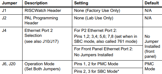
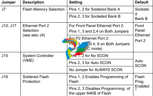
of other interface modules on the MVME5100. The following table lists the manually configured
jumpers on the MVME5100, and their default settings.
If you are resetting the board jumpers from their default settings, it is important to verify that all
settings are reset properly. For example, the SBC mode requires setting jumpers 4, 10 and 17 for
rear Ethernet functions, but it also requires resetting jumpers J6 and J20. Neglecting to reset J6 and
J20 could damage or destroy subsequent PMCs or PrPMCs installed on the base board at power-up.

Table 1-1. Manually Configured Headers/Jumpers (continued)

Introduction
This chapter provides information on hardware preparation and installation for the MVME5100
Series of Single Board Computers.
Note Unless otherwise specified, the designation “MVME5100” refers to all models of the
MVME5100-series Single Board Computers.
Getting Started
The following subsections include information helpful in preparing your equipment. It includes and
overview of the MVME5100, any equipment needed to complete the installation, and unpacking
instructions.
Overview and Equipment Requirements
The MVME5100 interfaces to a VMEbus system via its P1 and P2 connectors and contains two IEEE
1386.1 PCI Mezzanine Card (PMC) Slots. The PMC Slots are 64-bit and support both front and rear
I/O.
Additionally, the MVME5100 is user configurable by setting on-board jumpers. Two I/O modes are
possible: PMC mode or SBC mode (also called 761 or IPMC mode). The SBC mode uses the IPMC712
I/O PMC and the MVME712M Transiton Module, or the IPMC761 I/O PMC and the MVME761
Transition Module. The SBC mode is backwards compatible with the MVME761 transition card and
the P2 adapter card (excluding PMC I/O routing) used on the MVME2600/2700 product. This mode
is accomplished by configuring the on-board jumpers and by attaching an IPMC761 PMC in PMC
slot 1. Secondary Ethernet is configured to the rear.
PMC mode is backwards compatible with the MVME2300/MVME2400 and is accomplished by
simply configuring the on-board jumpers.
The following equipment list is appropriate for use in an MVME5100 system:
❏ PMCspan PCI expansion mezzanine module (mates with MVME5100)
❏ Peripheral Component Interconnect (PCI) Mezzanine Cards (PMCs) (installed on an
MVME5100 board)
❏ RAM500 memory mezzanine modules (installed on an MVME5100 board)
❏ VME system enclosure
❏ System console terminal
❏ Disk drives (and/or other I/O) and controllers
❏ Operating system (and/or application software)
Unpacking Instructions
Avoid touching areas of integrated circuitry; static discharge can damage these
circuits.
Note If the shipping carton(s) is/are damaged upon receipt, request that the carrier's agent be
present during the unpacking and inspection of the equipment.
Use ESD
Wrist Strap
Emerson strongly recommends that you use an antistatic wrist strap and a


