
LAUERfor the operating consoles PCS 009, PCS 090, PCS 095, PCS 095.1
for the operating consoles
PCS 009, PCS 090, PCS 095, PCS 095.1
The operating consoles PCStopline offer the
highest degree on perfection, unparalled in
design and function. PCStopline keeps everything under control - from the PCSmini to the
PCSmaxi, with a superior operating culture and
an unlimited setup freedom.
PCS, the first programmable operating console
with a large selection of "ready-to-use" operating functions or operating tools which are
simply selected via instructions. You can realize
even the most unuasal operating requests at
ease and in a minimum of time.
Today this way and tomorrow that way
One standard hardware for virtually thousands
of different operating situations. Without extensive wiring and dozens of I/O points.
PCS for operating. What else?
■ Machine operation using 8 (PCS 009, PCS 090) or 16 (PCS 095, PCS 095.1)
freely assignable keys. These F01 to F08/F16 labeled keys can be application
specifically inscribed and are provided to the controller as status bits.
■ Machine operation using 4 (PCS 009), 16 (PCS 090) or 32 (PCS 095, PCS
095.1) freely usable LEDs. These can be assigned the indicating states ON,
DARK, FLASHING, and INVERSE FLASHING. A green and a yellow LED is allocated
to each function key.
■ Display of fixed texts with integrated variable values. The values can be
represented selectably as numerical values or in text format.
■ Representation of the contents of 233 words as variables. In addition, 650
external variables can be defined. 9 variable formats (from bit to timer) are
available.
■ 3 text groups, 128 operating texts as menu and idle texts, 128 message texts
with up to 332 lines, 5 help texts with up to 32 lines.
■ 127 menus with 255 menu nodes each for any menu configurations.
■ 4 different deletion modes. For every message, 1 of 4 possible deletion modes
can be selected.
■ Modification of the content of any word within the transfer area. Using the
integrated editor all possible representation formats can be setup.
■ 7 priority levels for idle text up to help text, 3 message priorities Information,
Warning, Fault. This working-condition related management significantly offloads the programmable controller program.
■ Monitoring of rising or falling edges of 128 consecutive bits. The assignment
of texts, the manage-ment of 3 priority levels (Information, Warnings, and Faults),
keeping the timely sequence as much as possible, organization of the FIRST
MESSAGE, LAST MESSAGE, and CYCLIC DISPLAY, the individually settable deletion behaviour, and the representation formats NORMAL and FLASHING are tasks
which are managed by the PCS by itself.
■ Communication monitoring (wire-break, short circuit). A very efficient data
transfer is secured by the integrated priority management in connection with the
intelligent package length optimization, the high thruput rate and the fault tole
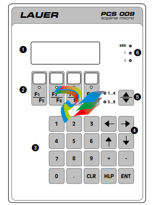
Operator Panel PCS 009
1 = LCD-Display, 4 lines each with 40 characters
2 = Function keys (also as soft keys) F1...F8 with a
greem message LED
3 = 10 key keyboard for nominal value input
4 = cursor and control keys for menus and nominal
value input
5 = Switch key (Shift key) for function keys (F1..F4,
F5..F9)
6 = Important information LEDs on the PCS status
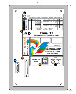
7 = Reset key
8 = DIL switch for the PCS 009
9 = Volume for acoustic signal
J = Serial interface RS 232/TTY for communication
K = Serial interface RS 422/RS 485 for communication
L = Operating voltage terminals
M = Fuse with reserve fuse
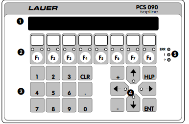
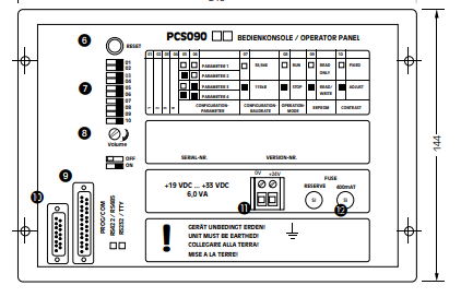
Operator Panel PCS 090
1 = LCD-display, 2 lines each with 40 characters
2 = Function keys (also as soft keys) F1...F8 with a
yellow and green message LED
3 = 10 key keyboard for nominal value input
4 = Cursor keys with LED and cursor control keys for
menus and nominal value input
5 = Important information LED's on the PCS status
6 = Reset key
7 = DIL-switch for the PCS 090
8 = Volume for acoustic signal
9 = Serial interface RS 232/TTY for the communication
J = Serial interface RS 422/RS 485 for the
communication
K = Operating voltage terminals
L = Fuse with reserve fuse
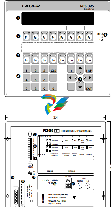
Operator Panel PCS 095/PCS 095.1
1 = LCD-display, 4 lines each with 40
characters
2 = Function keys (also soft keys) F1...F8
each with a yellow and a green
message LED
3 = Function keys F9...F16 each with a
yellow and a green mesage LED
4 = Ten key keyboard for nominal value
input
5 = Cursor key with LED and control key for
menu and nominal value input
6 = Important information LEDs on the PCS
status
7 = Reset key
8 = DIL switch for the PCS 095
9 = Volume for acoustic signals
J = Serial interface RS 232/TTY for the
communication
K = Serial interface RS 422/RS 485 for
the communication
L = Serial interface RS 232/TTY for the
programming and for the PCS 095.1
as Printer interface
M = Operating voltage terminals
N = Fuse with reserve fuse
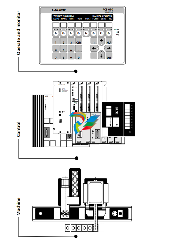
Communication between any PLC and the PCS occurs as follows:
The PCS writes in predetermined word areas of the PLC, functions or nominal values,
which the PLC then reads and interprets.
The PLC writes in predetermined word areas functions or actual values, which are
automatically read and interpreted by the PCS. Independently of the PLC there are
maximum 256 words of 16 bit, that is to say 4096 inputs / outputs for the PCS/PLC
communication available.
... and rapid set-up of a particular operational requirement
1 First define the specification and decide on the required PCS (PCS micro, PCS
mini, PCS midi or PCS maxi)
2 Allocate the word and bit number to variables (actual- and nominal values).
3 Create the texts for operational guidance and help functions as well as for
displays of machine conditions.
4 Determine the message texts and apply these words to them, subdivide the
message texts into 3 priority groups
■ Information
■ Warnings
■ Faults
and take into consideration the differing cancel modes, display and message
modes. Display and message modes can be altered by the PLC at any time.
5 Define the menus and the menu operating texts.
6 Transfer the data file (variables, texts, menus) which was made in the PC or PG
under MSDOS/DRDOS or compatible DOS-system, with the software PCSPRO
into the PCS.
7 Implement and parameterize the PLC specific operating software (PCS 91.nn,
see overall view of information) in the users' programme.
8 Connect the PCS via the adapter cable with the PLC. Test together the operation
and control of the PCS and PLC and adjust if necessary
Machines produce different parts. Therefore quick and selective alterations of finished
sizes and functions (variables) are especially important for increased flexibility.
The PCS features a convenient method of processing the variables. 650 external variables (freely definable) and 6 internal variables are supervised from the PCS.
The value of the external variables are stoped in the words
30...255. The PCS differentiates
between actual values and nominal values:
ACTUAL: The value in the word
is the actual value. The PCS can
only display the value.
NOMINAL: The standing value
in the word is the nominal value.
The value can be displayed and
changed by the PCS.
NOMINAL VALUE-P: The private value in the word is a nominal value. The PCS can display
the value. It can be changed only
if this is allowed by the word 14
bit 7 = log 1 (key switch or DILswitch 1...4 on the rear side of
the PCS). When the bit 7 of word
14 = log 0, the display of the
actual value follows.
Internal Variables
NAME CONTENTS FORMAT LENGTH ACTUAL/NOMINAL
ZP NUMBER OF INFORMATIONS BIN 3 ACTUAL
ZQ NUMBER OF WARNINGS BIN 3 ACTUAL
ZR NUMBER OF FAULTS BIN 3 ACTUAL
ZT MENU NUMBER BIN 2 ACTUAL
ZV SCROLL TIME BIN 2 NOMINAL
ZX INTERFACE FAULTS BIN 2 ACTUAL
External Variables
FORMAT, LENGTH
BIT variable max. length 40 characters
STRING variable max. length 40 characters
CSTRING variable max. length 40 characters
WORD variable KM, KH, KY: length: 17, 4, 7 characters
ASCII variable max. length 16 characters
BCD-1 variable max. length 4 digits
BCD0-1 variable *) max. length 4 digits
BCD-2 variable max. length 8 digits
BCD0-2 variable *) max. length 8 digits
BIN-1, BIN-A variable max. length 16 bits/11 digits
BIN0-1, BIN0-A variable *) max. length 16 bits/11 digits
BIN-2, BIN-B variable max. length 32 bits/11 digits
BIN0-2, BIN0-B variable *) max. length 32 bits/11 digits
VBIN-1, VBIN-A variable max. length 16 bits/11 digits + operational sign
VBIN0-1, VBIN0-A variable *) max. length 16 bits/11 digits + operational sign
VBIN-2,V BIN-B variable max. length 32 bits/11 digits + operational sign
VBIN0-2, VBIN0-B variable *) max. length 32 bits/11 digits + operational sign
Timer variable max. length 40 characters
*) BIN0...- and VBIN0... variable are only programmable with PCSPRO
The BIT variable
When two possibilities can be selected at an input, the descision is taken by the bit
variable. This is in the form of an ON/OFF switch.
Every switch position represents an inscription (text) which appears in the display.
Each bit variable occupies a bit. A data word can also take on up to 16 differing bit
variables or switches.
Example: A wood shavings vacuum absorption cleaner shall be switched on or off
in bit 2 data word 33.
The +/- switch selects the inscription or the switching position. The bit bears the value
of the inscription. The first inscription carries the value log 0, the second bears the
value log 1.
STRING variable
When two or more possibilities can be selected at an input, the decision is made by
the STRING variable. It corresponds to a selector switch.
With STRING variables, every switch position is classified with an inscribed text, which
appears in the display. Every STRING value carries a data word with up to 256 switch
positions. The switch position is deposited in low bytes of the data word.
Example: The frame material shall be selected in data word 40.
The inscription or switching position is selected with the +/- key. Acceptance follows
with the ENTER key.
CSTRING variable
The CSTRING variable corresponds to STRING variable. Acceptance follows directly
after using the +/- key without ENTER.
-
 HIRSCHMANN MSM20-M2M2M2M2SY9HH9E Ethernet media modul
 -
 HIRSCHMANN SPIDER-PL-20-05T1999999TWVHHHH Industrial Ethernet Rail Switch
 -
 Hirschmann SPIDER-PL-20-07T1M2M299TWVHHHH Industrial ETHERNET Rail Switch
 -
.png) Hirschmann (Belden) RS20-1600M2M2SDAEHC09.1.00 DIN-rail managed industrial Fast Ethernet switch
Hirschmann (Belden) RS20-1600M2M2SDAEHC09.1.00 DIN-rail managed industrial Fast Ethernet switch -
 Hirschmann (Belden) RS30-1602O6O6TDAPHC09.1.00 DIN-rail managed industrial Ethernet switch
 -
 Hirschmann (Belden) RS30-2402O6T1SDAPHH09.0.13 DIN-rail industrial Ethernet switch
 -
Hirschmann (Belden) SPIDER-PL-20-04T1S29999TY9HHHH Ethernet DIN-rail switch
-
 HIRSCHMANN RS20-1600T1T1SDAUHX Switch
 -
 HIRSCHMANN BRS42-0012OOOO-SPCZ99HHSES industrial switch
 -
 Hirschmann RS20-0800S2S2TDHPHH09.0.14 Fast Ethernet DIN rail switch.
 -
 HIRSCHMANN MM20-Z6Z6M2M2SAHH Hybrid Fast Ethernet Media Module
 -
 HIRSCHMANN MM20-Z6Z6T1T1SAHH hot-swappable hybrid Fast Ethernet Media Module
 -
 HIRSCHMANN MM20-P9P9T1T1SAHH Hybrid Fast Ethernet Media Module
 -
 HIRSCHMANN MM20-M4T1T1T1SAHH Hybrid Fast Ethernet Media Module
 -
 HIRSCHMANN MM20-M4M4T1T1SAHH Hybrid Fast Ethernet Media Module
 -
 HIRSCHMANN MM20-M2M2M2M2SZHH Ethernet media module
 -
HIRSCHMANN MM20-M2M2M2M2SAHH Ethernet media module
-
 HIRSCHMANN MM20-T1T1T1T1EBH 4-port Fast Ethernet Copper Cable Media Module
 -
HIRSCHMANN MM20-T1T1T1T1SAHH 4-port Fast Ethernet Copper Cable Media Module
-
HIRSCHMANN MM20-T1T1T1T1SAHH 4-port Fast Ethernet Copper Cable Media Module
-
 HIRSCHMANN MM20-Z6Z6EBH Hot-swappable fast Ethernet media module
 -
 HIRSCHMANN MM20-Z6Z6SAHH Ethernet media module
 -
HIRSCHMANN MM20-Z6Z6Z6Z6EBH Industrial Media Module
-
 MSM40-T1T1T1TZ9HH9E99.9.99 HIRSCHMANN Switch
 -
 HIRSCHMANN MS20-0800SAAEHC / MS20-0800SAAEHC0 8-port modular Layer 2 management Ethernet switch
 -
 Hirschmann RSPM20-4T14T1SZ9HHS9 Switch RSPM20-4T14T1SZ9HHS9
 -
 HIRSCHMANN RS20-1600M2M2SDAEHH09.1. RS20/30/40 Managed Switch configurator
 -
HIRSCHMANN RS20-1600M2M2SDAEHX09.0.00 Ethernet switch
-
 HIRSCHMANN BELDEN SPIDER-PL-20-07T1M2M299TY9HHHH / SPIDERPL2007T1M2M299TY9HHHH
 -
HIRSCHMANN MM3-1FXS2/3TX1 Switching Board Module
-
 HIRSCHMANN RSPE30-24044O7T99-ECCP999HHSE2A08.1.00 Industrial-grade fanless management-type Ethernet switch
 -
 HIRSCHMANN RS30-1602OOZZSDAEHC09.1.00 DIN-rail-mounted managed Layer 2 Ethernet switch
 -
 HIRSCHMANN MACH104-20TX-F Managed 24-port Full Gigabit 19" Switch
 -
 HIRSCHMANN Switch RS20-0800M4M4SDAE
 -
Hirschmann RS30-1602O6O6SDAEHH09.1. Management-type Ethernet switch
-
 Hirschmann RS30-1602OOZZSDAEHC09.0.10 Open rack-style Ethernet switch
 -
 HIRSCHMANN RSPE30-24044O7T99-SCCV999HHSI2SXX.X.XX High-Availability Seamless Redundancy
 -
HIRSCHMANN RSPE30-24044O7T99-SCCZ999HHSE2A DIN-rail Ethernet switch
-
HIRSCHMANN MM2-4TX1-EEC switch
-
HIRSCHMANN MSM40-T1T1T1T1TZ9HH9E99.9.99 Module
-
 HIRSCHMANN RS20 Rail Switch RS20-0400S4T1SDAEHC07.1.01
 -
 HIRSCHMANN M4-FAST8-SFP Fast Ethernet media module
 -
 HIRSCHMANN RS20-0400M2T1SDAP Managed Fast-Ethernet-Switch
 -
 HIRSCHMANN BELDEN SPIDER II 8TX/1FX EEC Industrial Ethernet Rail Switch
 -
HIRSCHMANN MM3-2FXS2/2TX1
-
 HIRSCHMANN RS2-4TX/1FX EEC Industrial Ethernet Rail Switch
 -
 RS30-0802O6O6SDAEHC09.0.10 HIRSCHMANN Switch
 -
 HIRSCHMANN m4-8TP-RJ45 Ethernet Media Module
 -
 HIRSCHMANN MSP30-24040SCZ9URHHE3A switch
 -
 Hirschmann rack MS30-1602SAAPHC
 -
 HIRSCHMANN RS2-FX/FX Industrial Switch Module
 -
Rs1txfx - Hirschmann - Rs1-Tx/Fx Rail Switch
-
RS20-0800S2S2SDAEHC09.1.00 HIRSCHMANN Commutator
-
 Hirschmann EAGLE20 TX/TX Industrial Security Router
 -
 Hirschmann SPIDER-SL-20-04T1S29999SY9HHHH Industrial Switch
 -
 HIRSCHMANN MAR1040-4C4C4C4C9999SMMHRHHXX.X. Gigabit Ethernet Switch configurator
 -
 Hirschmann MAR1040 Industrial Switch
 -
 HIRSCHMANN BELDEN RS30-1602O6O6SDAE
 -
Hirschmann RS20-1600M2M2SDAUHC Ethernet DIN rail switch
-
 HIRSCHMANN OCTOPUS 24M industrial switch
 -
 HIRSCHMANN RS20-1600T1T1SDAE Management-type Ethernet switch
 -
 HIRSCHMANN RS20-1600T1T1SDAUHH industrial switch
 -
HIRSCHMANN RS20-0800M2M2SDAPHC09.0.04 switch
-
 Hirschmann MR 8-03 24V DC Industrial Modular Bridge/Router
 -
 HIRSCHMANN RS20-0400M2T1SDAPHC08.0.01 Managed Switch
 -
 MACH1130 Hirschmann Industrial Switch
 -
 HIRSCHMANN 943824-002 SPIDER 5TX Industrial Ethernet Switch
 -
 HIRSCHMANN RS30-0802O6O6SDAEHC09.1.00 Managed Industrial Switch
 -
 HIRSCHMANN RS20-0400M2M2TDAEHC04.0.01 Industrial Switch
 -
 HIRSCHMANN BRS20-0600Z6Z6-STCZ99HHSES Industrial Switch
 -
 HIRSCHMANN MACH104-20TX-FR-L3P Industrial Ethernet Switch
 -
 HIRSCHMANN RS40-0009CCCCEDBPHH06.0.01 Industrial Switch
 -
 HIRSCHMANN RS2-3TX/2FX EEC Industrial Ethernet Switch
 -
 Hirschmann MACH 1020/1030 Fast/Gigabit Rack Mount Switches
 -
HIRSCHMANN RS20-0800M2M2SDAPHC09.0.14 Industrial Switch
-
 HIRSCHMANN RS20-1600T1T1SDAEHC09.0.04 Industrial Switch
 -
 HIRSCHMANN RSB20-0800T1T1EAABHH Industrial Switch
 -
 HIRSCHMANN MACH4002-48+4G-L3E Industrial Backbone Switch
 -
 HIRSCHMANN RS20-0400S2T1SDAE Industrial Managed Switch
 -
HIRSCHMANN RS20-0800S2T1SDAUHC Industrial Switch
-
 HIRSCHMANN RS20-2400S4S4SDAEHC09.0.14 industrial switch
 -
 HIRSCHMANN OS20-001200T5T5T5- TBBZ999HHNE3S 08.1.00 industrial switch
 -
HIRSCHMANN OS20-001200T5T5T5- TBBZ999HHNE3S 08.1.00 industrial switch
-
 HIRSCHMANN RS40-0009CCCCSDAEHH09.0.14 switch
 -
 Hirschmann RS20-1600T1T1SDAUHC Management-type Ethernet Switch
 -
 Hirschmann M1-8SFP Switche
 -
Hirschmann Industrial Ethernet Ruggedized Switch MACH1000 Family
-
 Basler Electric, Solid State Protective Relay, BE1-60
 -
BASLER ELECTRIC SR4A-2B15B3A Static Voltage Regulator
-
.png) BASLER ELECTRIC EXCITER DIODE MONITOR EDM-200
BASLER ELECTRIC EXCITER DIODE MONITOR EDM-200 -
.png) BASLER ELECTRIC DECS125-15-B2C5 DIGITAL EXCITATION CONTROL SYSTEM V 2.0.9
BASLER ELECTRIC DECS125-15-B2C5 DIGITAL EXCITATION CONTROL SYSTEM V 2.0.9 -
 BASLER ELECTRIC BE1-851 OVERCURRENT PROTECTION RELAY MECHANISM
 -
 Basler Electric BE1-51A / BE151A
 -
 Basler Electric BE1-40Q Loss of Excitation Relay
 -
 Basler Electric BE1-87G Variable Percentage Differential Relay
 -
 Basler Electric BE1-11 Protection System I5A3M2P2N0EA00
 -
 BASLER ELECTRIC DECS-200-1C Digital Excitation Control System
 -
 Basler Electric / Kohler BE1-11g Generator Protection Relay G5A3M2J2N0E000
 -
BASLER ELECTRIC DECS125-15 DIGITAL EXCITATION CONTROL SYSTEM
-
 BASLER ELECTRIC BE1-951 OverCurrent Protecton System
 -
Basler Electric DECS-200-1L Digital Excitation Control System
-
 Basler Electric DGC-2020HD-5NS1DNSBA Digital Genset Controller -
 -
 BASLER ELECTRIC BE1-81T1EE1WA0N1F / BE181T1EE1WA0N1F
 -
 BASLER ELECTRIC BE1-25M1EA6PN5R1F / BE125M1EA6PN5R1F
 -
 BASLER ELECTRIC DECS-250-LN1SN1N DIGITAL EXCITATION CONTROL SYSTEM
 -
Basler Electric DECS-250-CN2CN 1N Digital Excitation Control System Unit
-
 BASLER ELECTRIC DECS-300-C0N0 DIGITAL EXCITATION CONTROL SYSTEM
 -
 BASLER ELECTRIC BE1-87T-A1E-A1J-D0S1F / BE187TA1EA1JD0S1F
 -
BASLER ELECTRIC BE1-11-G6D1M0J2P0E000 Protection System
-
 BASLER ELECTRIC BE1-GPS100-E4N1H1N GENERATOR PROTECTION SYSTEM
 -
 Jaquet Relay card (Auxiliary module) FTV 3090 377Z-03985
 -
 Jaquet Trip Chain Control card FTBU 3034 377Z-05030
 -
 Jaquet with input card -E04 FTFU 3024 -E04 377Z-05855
 -
 Jaquet with input card -E03 FTFU 3024- E03 377Z-03983
 -
 Jaquet FTFU 3024- E02 377Z-03982 with input card -E02
 -
 Jaquet FTFU 3024-E01 377Z-03981 with input card -E01
 -
 Hirschmann RS20-2400T1T1SDAE Industrial Managed Ethernet Switch
 -
 Hirschmann BELDEN EAGLE30-04022O6TT999SCCV9HSE3F
 -
 Hirschmann MM3-2FXS2/2TX MICE Media Module
 -
 Hirschmann RS20-1600M2M2SDAPHC08.0.05 Industrial Managed Switch
 -
 Hirschmann OZD Profi 12M G12-1300 PRO Fieldbus Repeater
 -
Hirschmann SPIDER 4TX/1FX-ST EEC Industrial Ethernet Switch
-
 Hirschmann MM2-2FXM3/2TX1 MICE Media Module
 -
 Hirschmann RS20-2400M2M2SDAPHC09.0.14 Industrial Switch
 -
 Hirschmann RS20-0400M2M2SDAEHC07.1.05 OpenRail Switch
 -
 Hirschmann OZD Profi 12M G12-EEC Fieldbus Repeater
 -
HIRSCHMANN MDA422-1/2-3.5c-23/46 sensor
-
Hirschmann RS30-2402T1T1SDAUHC Managed Industrial Switch


