
GE Energy Mark* VIe Control Product Description
Introduction
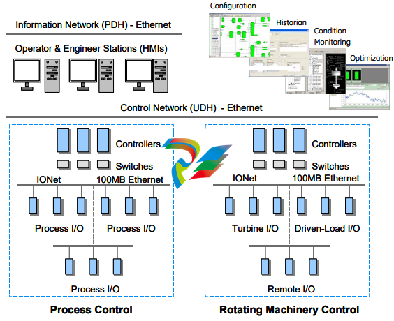
Mark* VIe is a flexible control system for multiple applications. It features highspeed, networked I/O for simplex, dual, and triple redundant systems. Industrystandard Ethernet communications are used for I/O, controllers, and supervisory
interface to operator and maintenance stations, and third-party systems.
ToolboxST* is used for Mark VIe and related controls as a common software
platform for programming, configuring I/O, trending, and analyzing diagnostics. It
provides a single source of quality, time-coherent data at the controller and plant
level for effectively managing equipment assets.
Architecture
A single-board controller is the heart of the system. It includes the main processor
and redundant Ethernet drivers for communicating with networked I/O and
additional Ethernet drivers for the control network. A QNX® real-time, multitasking
operating system is used for the main processor and I/O. Application software is
provided in a configurable control block language, and is stored in non-volatile
memory. It conforms to IEEE-854 32-bit floating-point format.
IONet is a dedicated, full-duplex, point-to-point protocol that provides a
deterministic, high-speed 100 MB communications network suitable for local or
remote I/O with a fiber interface. It provides communication between the main
processor(s) and networked I/O blocks, called I/O packs.
100 MB Ethernet is used for
communication to local and
remote I/O packs. The IONet
is available in single, dual,
and triple configurations.
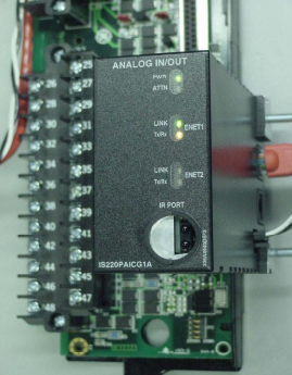
Each I/O pack is mounted on a board with barrier or box-type terminal blocks. The
I/O pack contains two Ethernet ports, a power supply, a local processor, and a data
acquisition board. Computation power grows as I/O packs are added to the control
system, enabling an overall control system frame rate of 10 ms in simplex, dual, or
triple redundant configuration. Some process sub-systems require even more
performance; therefore, the local processors in each I/O pack run algorithms at
higher rates as required for the application.
Redundancy
Every application has different requirements for redundancy depending on the
importance of the process. Mark VIe provides a wide range of redundancy options
that can be supplied in virtually any combination and mounted local or remote. Some
of these redundancy options include:
• Power sources and supplies single, dual, and triple
• Controllers (main processor) single, dual, and triple
• I/O network redundancy single, dual, and triple
• I/O packs per terminal board single, dual, and triple
• Ethernet Ports / I/O pack single or dual
System Architecture
Controllers are continuously online and read input data directly from IONet. Dual
redundant systems transmit inputs from one or redundant I/O packs on dual IONets
to dual controllers. Outputs are transmitted to an output I/O pack that selects either
the first healthy signal or the signal of choice. Three output packs can be provided to
vote output signals for mission-critical field devices.
Dual redundant systems can be configured for single, dual, and triple sensors. Their
dual internal networks and controllers keep the process online if a controller or
power supply fails. Triple redundant systems are available to protect against soft or
partial failures of devices that continue to run but with incorrect signals/data.
These systems out vote a failed component with a 2-out-of-3 selection of the signal.
Application software in all three controllers runs on the voted value of the signal
while diagnostics identify the failed device. These sophisticated diagnostics
minimize the mean-time-to-repair (MTTR) while the on-line repair capability
maximizes the mean-time-between-forced-outages (MTBFO). Field sensors for these
systems can be single, dual, or triple.
A second controller can be provided to separate the application software for different
pieces of equipment. For example, a core engine control for an air-fuel governor can
run in one controller while a second controller can be dedicated to auxiliary control.
Note Every I/O pack communicates directly on IONet, which enables each I/O pack
to be replaced individually without affecting any other I/O in the system. Also, the
I/O pack can be replaced without disconnecting any field wiring.
I/O Interface
One or multiple I/O packs are mounted on each board to digitize the sensor signal,
perform algorithms, and communicate with a separate controller that contains the
main processor. I/O packs have a local processor board that runs a QNX operating
system and a data acquisition board that is unique to the type of input device. Local
processors run algorithms at faster speeds than the overall control system.
An on-board temperature sensor
provides continuous monitoring of
the environment in remote
locations.
An infrared transceiver is useful for low-level diagnostics. I/O values can be
monitored, I/O pack host/function names can be programmed, and error statuses can
be checked. This requires a Windows®-based diagnostic tool on a laptop or a
handheld computer.
• Dual 100 MB Ethernet ports
• 100 MB full duplex ports
• Online repair per I/O pack
• Operation -30°C to 65°C (-22 °F to 149 °F)
• Accuracy -30°C to 65°C (-22 °F to 149 °F)
• I/O packs rated Class 1, Div. 2
• Ambient temperature sensor
• LEDs: power status and attention
• LEDs: Ethernet link-connected and communication-active
• LEDs: application-specific
• Processor: 32-bit RISC CPU 266 mHz
• Infrared Transceiver: Low level diagnostics, monitor I/O,
set host/function names, error status
• Power: 28 V dc (typical)
• Internal solid-state circuit breaker and soft start
The I/O Processor contains a temperature sensor that is accurate to within ±2°C
(±3.6 °F). Detection of an excessive temperature generates a diagnostic alarm, and
the logic is available in the database (signal space) to facilitate additional control
action or unique process alarm messages. In addition, the temperature is
continuously available in the database.
A power supply provides a regulated 28 V dc power feed to each I/O pack. The
negative side of the 28 V dc is grounded through the I/O pack metal enclosure and its
mounting base. The positive side has solid-state circuit protection built-into the I/O
pack with a nominal 2 A trip point. Online repair is possible by removing the
28 V dc connector, replacing the I/O pack, reinserting the power connector, and
downloading software from the software maintenance tools.
Note Every I/O pack communicates directly on IONet, which enables each I/O pack
to be replaced individually without affecting any other I/O in the system. Also, the
I/O pack can be replaced without disconnecting any field wiring
Terminal Blocks
Signal flow begins with a sensor connected to a terminal block on a board. There are
two types of boards available. T-type boards contain two 24 point, barrier-type,
removable, terminal blocks. Each point can accept two 3.0 mm2
(#12AWG) wires
with 300 V insulation per point with spade or ring type lugs. In addition, captive
clamps are provided for terminating bare wires. Screw spacing is 9.53 mm (0.375
inch) minimum, center-to-center.
A shield strip is provided next to each block, which is actually the left-hand side of
the metal base where the board is mounted. Wide and narrow boards are arranged in
vertical columns of high and low-level wiring that can be accessed from top and/or
bottom cable entrances. An example of a wide board is a board that contains
magnetic relays with fused circuits for solenoid drivers. T-type boards are normally
surface mounted, but can also be DIN-rail mounted.
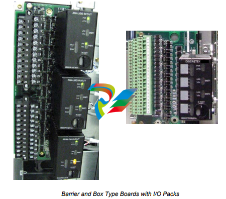
S-type boards have one I/O pack for simplex and dual redundant systems. They are
half the size of T-type boards and are DIN-rail or surface mounted. Two versions of
the boards are available, H1 and H3. H1 boards have fixed terminal blocks, and H3
boards have removable terminal blocks. A H2 version is available for mounting of
custom blocks such as spring-cage or insulation displacement.
S-type boards have box type terminal blocks that accept one 3.0 mm2
(#12AWG)
wire or two 2.0 mm2
(#14AWG) wires with 300 V insulation per point. Screw
spacing is 5.08 mm (0.2 inch) minimum, center-to-center. A shield strip is provided
to the left of each block. It can be connected to a metal base for immediate grounding
or floated to allow individual ground wires from each board to be wired to a
centralized, cabinet ground strip.
I/O Types
General purpose I/O is used for both turbine applications and process control.
Turbine-specific I/O is used for direct interface to the unique sensors and actuators
on turbines. This reduces or eliminates a substantial amount of interposing
instrumentation. As a result, many potential single point failures are eliminated in the
most critical area for improved running reliability and reduced long-term
maintenance. Direct interface to the sensors and actuators also enables the
diagnostics to directly interrogate the devices on the equipment for maximum
effectiveness. This data is used to analyze device and system performance. Also,
fewer spare parts are needed.
I/O Type - General Purpose Board
Redundant
Packs/Boards
24 DI (125 V dc, group isolated) 1 ms SOE TBCIH1 1 or 2 or 3
24 DI (24 V dc, group isolated) 1 ms SOE TBCIH2 1 or 2 or 3
24 DI (48 V dc, group isolated) 1 ms SOE TBCIH3 1 or 2 or 3
24 DI (115/230 V ac, 125 V dc, point isolated) 1 ms SOE on 125 V dc TBCIH1 1 or 2 or 3
24 DI (24 V dc, point isolated) TBCIH2 1 or 2 or 3
24 DI (24 V dc, group isolated) STCIH1 1
12 C mechanical relays w/6 solenoids, coil diagnostics (115/230 V ac, 24/125 V dc) TRLYH1B 1 or 3
12 C mechanical relays w/6 solenoids, voltage diagnostics (115/230 V ac, 125 V dc) TRLYH1C 1 or 3
12 C mechanical relays w/6 solenoids, voltage diagnostics (24 V dc) TRLYH2C
6 A mechanical relays for solenoids, solenoid impedance diagn. (24/125 V dc) TRLYH1D 1 or 3
12 A solid-state relays/inputs (115/230 V ac) TRLYH1E 1 or 3
12 A solid-state relays/inputs (125 V dc) TRLYH2E 1 or 3
12 A solid-state relays/inputs (24 V dc) TRLYH3E 1 or 3
36 mechanical relays, 12 voted form A outputs TRLYH1F 3
12 fused branches WPDFH1A
36 mechanical relays, 12 voted form B outputs TRLYH2F 3
12 fused branches WPDFH2A
10 AI (V/I inputs) and (2AO (4-20/0-200 mA outputs) TBAIH1C 1 or 2 or 3
10 AI (V/I inputs) and (2AO (4-20/0-200 mA outputs) STAIH1A 1 or 2 or 3
16 AO (4-20 mA outputs) 8 per I/O pack TBAOH1C 1 or 2
8 AO (4-20 mA outputs) STAOH1A 1
12 thermocouples TBTCH1B 1 or 2 or 3
24 thermocouples (12 per I/O pack) TBTCH1C 1 or 2
12 thermocouples STTCH1A 1
16 RTDs 3 wires/RTD (8 per I/O pack) TRTDH1C 1 or 2
8 RTDs 3 wires/RTD SRTDH1A 1
6 serial ports for I/O drivers RS-232, RS422, RS485 SSCAH1A 1
10/2 analog I/O - HART communications SHRAH1A 1
PROFIBus communications SPIDH1A 1
I/O Type - Turbine Board
Redundant
Packs/Boards
Mixed I/O: 4 speed inputs/pack, synchronizing, shaft V/I monitor TTURH1C 1 or 3
2 servo channels: up to 3 coils, 4 LVDTs/channel, includes excitation TSVCH1A 1 or 3
8 vibration (seismic, proximity, accel.), 4 position, 1 reference probe, buffered out TVBAH1A 1 or 2 or 3
Controller
Features
• Single board including:
Main Processor
Control Network Communications - Ethernet
IO Network Communications – Ethernet
USB and COM ports
• Processor: Freescale 8349, 667MHz
• Operating system: QNX
• Base mounting
• Status LEDs
Environment
• Operating temperature 0°C to +65 °C
• No fans required
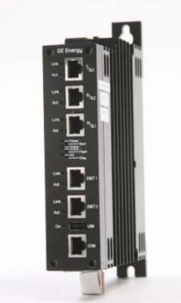
Mark VIe Controller
The single-board controller is a
compact and flexible design for
processing and network
communications.
The controller is a single board, which is base-mounted in the cabinet. For dual and
triple redundant systems, a second and third board can be mounted adjacent for a
compact packaging arrangement. An 8349, 667 MHz processor is provided with a
QNX operating system. The board is powered by 18-36 V dc, 12 watt source.
This rugged design is rated for an operating range of 0 to 65°C (32 to 149 °F) to
match the maximum operating temperature of the I/O modules. Also, it does not
require any cooling fans even at maximum temperature, and is suitable for NFPA
Class 1, Div. 2 applications.
Each controller has three 100 MB Ethernet drivers for the IONet, so that each
controller can communicate with up to three network switches. In redundant systems,
this allows each controller to monitor redundant inputs directly and compare them
for any potential discrepancies. Connectors are color-coded and labeled to simplify
maintenance.
Controllers also have two Ethernet drivers for the control network to communicate
peer-to-peer with other Mark VI, Mark VIe, and EX2100 generator excitation
controls, as well as operator and maintenance stations. Controllers can be
synchronized between units or to a local or remote time source for accurate plantwide sequence of events monitoring.
Switches manage the
communication traffic to
eliminate collisions and
increase network determinism
Communication between the controller and the I/O packs is performed with the
internal IONet. This is a 100 MB Ethernet network available in non-redundant, dual
redundant, and triple redundant configurations. Ethernet Global Data (EGD) and
other protocols are used for communication. EGD is based on the UDP/IP standard
(RFC 768). EGD packets are broadcast at the system frame rate from the controller
to the I/O packs, which respond with input data.
IONet conforms to the IEEE 802.3 standard. It is supplied as 100BaseTx and
100BaseFx (fiber) for greater distances, noise rejection, lightning immunity, and
ground immunity. A star topology is used with the controller on one end, a network
switch in the middle, and I/O packs at the end
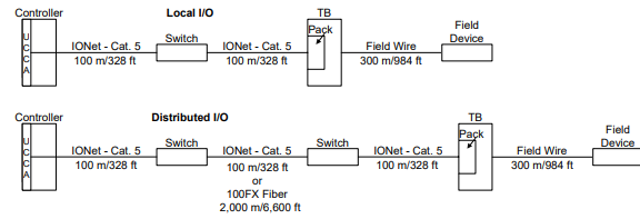
Maximum IONet Distances Including Field Devices
Industrial grade switches are used for the IONet that meet the codes, standards,
performance, and environmental criteria for industrial applications including an
operating temperature of -40°C to 85°C (-40 °F to 185 °F) and Class 1, Div. 2.
Switches have provision for redundant 10 to 30 V dc power sources (200/400 mA)
and are mounted on a DIN-rail. LEDs indicate the status of the IONet link, speed,
activity, and duplex.
100BaseTx 100BaseFx
IEEE specification 802.3u 802.3u
Wire speed 100 Mbps 100 Mbps
Cable type UTP Cat. 5 Fiber (multi-mode)
Connector type RJ-45 SC
Maximum length of a segment at full-duplex 100 m/328 ft 2 km/6,600 ft
Maximum taps per segment 2 2
Maximum I/O packs per network 199 199
Maximum number of switches 2 2
Topology Star Star
Operator and Maintenance Tools
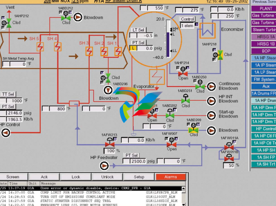
Operator Interface
The operator interface is commonly referred to as the Human-Machine Interface
(HMI). It is a computer with a Microsoft® Windows-based operating system,
client/server capability, a CIMPLICITY® graphics display system, and software
maintenance tools (ToolboxST). It can be applied as:
• Primary operator station for one unit or the entire plant
• Maintenance station gateway
• Engineers station
• Gateway for communications
All local and remote data in
the Mark VIe is accessible for
screens with high-resolution
time tags for alarms and
events.
The HMI can be re-initialized or replaced with the process running with no impact
on the control system. It communicates with the main processor board in the Mark
VIe controller(s) through the control network Unit Data Highway (UDH) and to
third-party control and monitoring systems through the information network Plant
Data Highway (PDH).
System (process) alarms for fault conditions are time-tagged at frame rate in the
controller(s) and transmitted to the HMI alarm management system. System events
are time-tagged at frame rate, and sequence of events (SOE) for contact inputs are
time-tagged at 1 ms in the I/O packs. Alarms can be sorted according to ID,
Resource, Device, Time, and Priority. Operators can add comments to alarm
messages or link specific alarm messages to supporting graphics.
A standard alarm/event log stores data for 30 days and can be sorted in chronological
order or according to the frequency of occurrence. In addition, a trip history is
provided that stores the key control parameters and alarms/events for the last 30
trips. This includes up to 200 alarms, 200 events, 200 SOE messages, and analog
data before and after the trip.
Data is displayed in English or Metric engineering units with a one-second update
rate and one second to repaint a typical display graphic. Operator commands can be
issued to increment/decrement a setpoint, or a numerical value can be entered for a
new setpoint.
Security for HMI users is important to restrict access to certain maintenance
functions, such as editors and tuning capability, and to limit certain operations.
A system called User Accounts is provided to limit access or use of particular HMI
features.
Software Maintenance Tools (ToolboxST)
The Mark VIe is a fully programmable control system. Application software is
maintained by factory software automation tools that select proven GE control and
protection algorithms and integrate them with the I/O, sequencing, and displays for
each application. Multiple block libraries are provided with general-purpose blocks,
math blocks, macros (user blocks), and application-specific blocks.
Changes to the application software can be made with multi-level password
protection and downloaded to the controller(s) while the system is running without
rebooting the main processors. In redundant control systems, the application
software in each controller is identical, and is represented as a single program to
maintenance personnel. Downloads of changes are automatically distributed to the
redundant controllers by the control system, and any discrepancies between the
controllers are monitored by diagnostics. All application software is stored in the
controller(s) in non-volatile memory.
Application software is run sequentially, and dynamic data displays in function block
and ladder diagram formats. Maintenance personnel can add, delete, or change
analog loops, sequencing, I/O assignments, and tuning constants. To simplify
editing, data points can be selected, dragged, and dropped on the screen from one
block to another. Points can also be dragged from the application software diagrams
onto trends. Other features include Boolean (digital) forcing, analog forcing, and
trending at the rate the application software is running, frame rate.
Application software documentation is created directly from source code and can be
compiled and printed at the site. This includes the application software diagram, I/O
assignments, the settings of tuning constants, and such. The software maintenance
tools are available for use in the HMI or as a separate software package on a
Windows-based computer.
Diagnostics
High/low (hardware) limit checking is provided for each analog input. These limits
are not configurable, and are selected to be outside the normal operating range but
inside the linear hardware operational range (before the hardware reaches saturation).
Diagnostic messages for hardware limit checks and all other hardware diagnostics
for the board can be accessed with the software maintenance tools. A composite
diagnostic alarm state is provided in the database for each I/O pack, and a separate
logic state is provided to indicate a high/low (hardware) limit fault of any analog
input or the associated communications for that signal.
Diagnostic and system (process) alarms are time-stamped in the controller(s) and
transmitted to operator and maintenance stations. Communication links to a plantdistributed control system (DCS) can contain both the software (system) diagnostics
and composite hardware diagnostics.
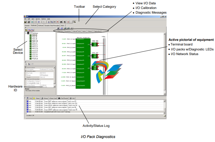
Diagnostic LEDs are provided on I/O packs as previously shown for the Analog I/O
pack. Standard LEDs indicate: power status, attention (abnormality detected),
Ethernet link connected, and Ethernet link communicating. LEDs on discrete I/O
packs also indicate the status of each point. All boards feature an electronic ID that
contains the board name, revision, and a unique serial number. When power is
applied to the I/O processor, it reads the ID of the terminal board, application board,
and itself. It then uses this information for a start permissive, diagnostics, and system
asset management. Since the terminal boards can be mounted remote at the
equipment, local temperature sensors monitor the temperature at each I/O pack.
Excessive temperature causes an alarm message. The alarm state and current
temperature value are available for display and for use in the application software
Plant level control systems integrate the diagnostic data from the individual turbine
and generator controls with the overall plant. This allows maintenance personnel to
quickly identify the defective control node, switch, or station and locate the
particular device needing service.
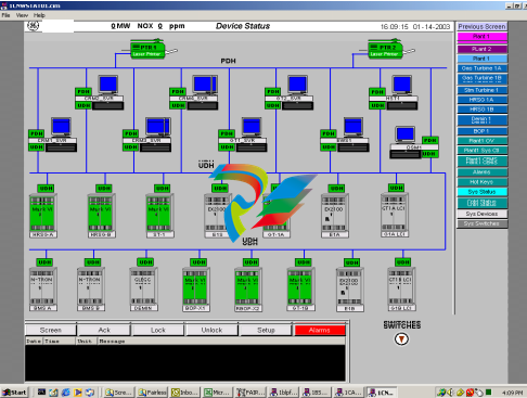
Network Diagnostics for:
z Operator Stations
z Maintenance Stations
z Engineers Stations
z Switches on:
- Plant Data Highway
- Unit Data Highway
- IONet
z Control Nodes
- Boards Within Nodes
- I/O Packs
-
 HIRSCHMANN MSM20-M2M2M2M2SY9HH9E Ethernet media modul
 -
 HIRSCHMANN SPIDER-PL-20-05T1999999TWVHHHH Industrial Ethernet Rail Switch
 -
 Hirschmann SPIDER-PL-20-07T1M2M299TWVHHHH Industrial ETHERNET Rail Switch
 -
.png) Hirschmann (Belden) RS20-1600M2M2SDAEHC09.1.00 DIN-rail managed industrial Fast Ethernet switch
Hirschmann (Belden) RS20-1600M2M2SDAEHC09.1.00 DIN-rail managed industrial Fast Ethernet switch -
 Hirschmann (Belden) RS30-1602O6O6TDAPHC09.1.00 DIN-rail managed industrial Ethernet switch
 -
 Hirschmann (Belden) RS30-2402O6T1SDAPHH09.0.13 DIN-rail industrial Ethernet switch
 -
Hirschmann (Belden) SPIDER-PL-20-04T1S29999TY9HHHH Ethernet DIN-rail switch
-
 HIRSCHMANN RS20-1600T1T1SDAUHX Switch
 -
 HIRSCHMANN BRS42-0012OOOO-SPCZ99HHSES industrial switch
 -
 Hirschmann RS20-0800S2S2TDHPHH09.0.14 Fast Ethernet DIN rail switch.
 -
 HIRSCHMANN MM20-Z6Z6M2M2SAHH Hybrid Fast Ethernet Media Module
 -
 HIRSCHMANN MM20-Z6Z6T1T1SAHH hot-swappable hybrid Fast Ethernet Media Module
 -
 HIRSCHMANN MM20-P9P9T1T1SAHH Hybrid Fast Ethernet Media Module
 -
 HIRSCHMANN MM20-M4T1T1T1SAHH Hybrid Fast Ethernet Media Module
 -
 HIRSCHMANN MM20-M4M4T1T1SAHH Hybrid Fast Ethernet Media Module
 -
 HIRSCHMANN MM20-M2M2M2M2SZHH Ethernet media module
 -
HIRSCHMANN MM20-M2M2M2M2SAHH Ethernet media module
-
 HIRSCHMANN MM20-T1T1T1T1EBH 4-port Fast Ethernet Copper Cable Media Module
 -
HIRSCHMANN MM20-T1T1T1T1SAHH 4-port Fast Ethernet Copper Cable Media Module
-
HIRSCHMANN MM20-T1T1T1T1SAHH 4-port Fast Ethernet Copper Cable Media Module
-
 HIRSCHMANN MM20-Z6Z6EBH Hot-swappable fast Ethernet media module
 -
 HIRSCHMANN MM20-Z6Z6SAHH Ethernet media module
 -
HIRSCHMANN MM20-Z6Z6Z6Z6EBH Industrial Media Module
-
 MSM40-T1T1T1TZ9HH9E99.9.99 HIRSCHMANN Switch
 -
 HIRSCHMANN MS20-0800SAAEHC / MS20-0800SAAEHC0 8-port modular Layer 2 management Ethernet switch
 -
 Hirschmann RSPM20-4T14T1SZ9HHS9 Switch RSPM20-4T14T1SZ9HHS9
 -
 HIRSCHMANN RS20-1600M2M2SDAEHH09.1. RS20/30/40 Managed Switch configurator
 -
HIRSCHMANN RS20-1600M2M2SDAEHX09.0.00 Ethernet switch
-
 HIRSCHMANN BELDEN SPIDER-PL-20-07T1M2M299TY9HHHH / SPIDERPL2007T1M2M299TY9HHHH
 -
HIRSCHMANN MM3-1FXS2/3TX1 Switching Board Module
-
 HIRSCHMANN RSPE30-24044O7T99-ECCP999HHSE2A08.1.00 Industrial-grade fanless management-type Ethernet switch
 -
 HIRSCHMANN RS30-1602OOZZSDAEHC09.1.00 DIN-rail-mounted managed Layer 2 Ethernet switch
 -
 HIRSCHMANN MACH104-20TX-F Managed 24-port Full Gigabit 19" Switch
 -
 HIRSCHMANN Switch RS20-0800M4M4SDAE
 -
Hirschmann RS30-1602O6O6SDAEHH09.1. Management-type Ethernet switch
-
 Hirschmann RS30-1602OOZZSDAEHC09.0.10 Open rack-style Ethernet switch
 -
 HIRSCHMANN RSPE30-24044O7T99-SCCV999HHSI2SXX.X.XX High-Availability Seamless Redundancy
 -
HIRSCHMANN RSPE30-24044O7T99-SCCZ999HHSE2A DIN-rail Ethernet switch
-
HIRSCHMANN MM2-4TX1-EEC switch
-
HIRSCHMANN MSM40-T1T1T1T1TZ9HH9E99.9.99 Module
-
 HIRSCHMANN RS20 Rail Switch RS20-0400S4T1SDAEHC07.1.01
 -
 HIRSCHMANN M4-FAST8-SFP Fast Ethernet media module
 -
 HIRSCHMANN RS20-0400M2T1SDAP Managed Fast-Ethernet-Switch
 -
 HIRSCHMANN BELDEN SPIDER II 8TX/1FX EEC Industrial Ethernet Rail Switch
 -
HIRSCHMANN MM3-2FXS2/2TX1
-
 HIRSCHMANN RS2-4TX/1FX EEC Industrial Ethernet Rail Switch
 -
 RS30-0802O6O6SDAEHC09.0.10 HIRSCHMANN Switch
 -
 HIRSCHMANN m4-8TP-RJ45 Ethernet Media Module
 -
 HIRSCHMANN MSP30-24040SCZ9URHHE3A switch
 -
 Hirschmann rack MS30-1602SAAPHC
 -
 HIRSCHMANN RS2-FX/FX Industrial Switch Module
 -
Rs1txfx - Hirschmann - Rs1-Tx/Fx Rail Switch
-
RS20-0800S2S2SDAEHC09.1.00 HIRSCHMANN Commutator
-
 Hirschmann EAGLE20 TX/TX Industrial Security Router
 -
 Hirschmann SPIDER-SL-20-04T1S29999SY9HHHH Industrial Switch
 -
 HIRSCHMANN MAR1040-4C4C4C4C9999SMMHRHHXX.X. Gigabit Ethernet Switch configurator
 -
 Hirschmann MAR1040 Industrial Switch
 -
 HIRSCHMANN BELDEN RS30-1602O6O6SDAE
 -
Hirschmann RS20-1600M2M2SDAUHC Ethernet DIN rail switch
-
 HIRSCHMANN OCTOPUS 24M industrial switch
 -
 HIRSCHMANN RS20-1600T1T1SDAE Management-type Ethernet switch
 -
 HIRSCHMANN RS20-1600T1T1SDAUHH industrial switch
 -
HIRSCHMANN RS20-0800M2M2SDAPHC09.0.04 switch
-
 Hirschmann MR 8-03 24V DC Industrial Modular Bridge/Router
 -
 HIRSCHMANN RS20-0400M2T1SDAPHC08.0.01 Managed Switch
 -
 MACH1130 Hirschmann Industrial Switch
 -
 HIRSCHMANN 943824-002 SPIDER 5TX Industrial Ethernet Switch
 -
 HIRSCHMANN RS30-0802O6O6SDAEHC09.1.00 Managed Industrial Switch
 -
 HIRSCHMANN RS20-0400M2M2TDAEHC04.0.01 Industrial Switch
 -
 HIRSCHMANN BRS20-0600Z6Z6-STCZ99HHSES Industrial Switch
 -
 HIRSCHMANN MACH104-20TX-FR-L3P Industrial Ethernet Switch
 -
 HIRSCHMANN RS40-0009CCCCEDBPHH06.0.01 Industrial Switch
 -
 HIRSCHMANN RS2-3TX/2FX EEC Industrial Ethernet Switch
 -
 Hirschmann MACH 1020/1030 Fast/Gigabit Rack Mount Switches
 -
HIRSCHMANN RS20-0800M2M2SDAPHC09.0.14 Industrial Switch
-
 HIRSCHMANN RS20-1600T1T1SDAEHC09.0.04 Industrial Switch
 -
 HIRSCHMANN RSB20-0800T1T1EAABHH Industrial Switch
 -
 HIRSCHMANN MACH4002-48+4G-L3E Industrial Backbone Switch
 -
 HIRSCHMANN RS20-0400S2T1SDAE Industrial Managed Switch
 -
HIRSCHMANN RS20-0800S2T1SDAUHC Industrial Switch
-
 HIRSCHMANN RS20-2400S4S4SDAEHC09.0.14 industrial switch
 -
 HIRSCHMANN OS20-001200T5T5T5- TBBZ999HHNE3S 08.1.00 industrial switch
 -
HIRSCHMANN OS20-001200T5T5T5- TBBZ999HHNE3S 08.1.00 industrial switch
-
 HIRSCHMANN RS40-0009CCCCSDAEHH09.0.14 switch
 -
 Hirschmann RS20-1600T1T1SDAUHC Management-type Ethernet Switch
 -
 Hirschmann M1-8SFP Switche
 -
Hirschmann Industrial Ethernet Ruggedized Switch MACH1000 Family
-
 Basler Electric, Solid State Protective Relay, BE1-60
 -
BASLER ELECTRIC SR4A-2B15B3A Static Voltage Regulator
-
.png) BASLER ELECTRIC EXCITER DIODE MONITOR EDM-200
BASLER ELECTRIC EXCITER DIODE MONITOR EDM-200 -
.png) BASLER ELECTRIC DECS125-15-B2C5 DIGITAL EXCITATION CONTROL SYSTEM V 2.0.9
BASLER ELECTRIC DECS125-15-B2C5 DIGITAL EXCITATION CONTROL SYSTEM V 2.0.9 -
 BASLER ELECTRIC BE1-851 OVERCURRENT PROTECTION RELAY MECHANISM
 -
 Basler Electric BE1-51A / BE151A
 -
 Basler Electric BE1-40Q Loss of Excitation Relay
 -
 Basler Electric BE1-87G Variable Percentage Differential Relay
 -
 Basler Electric BE1-11 Protection System I5A3M2P2N0EA00
 -
 BASLER ELECTRIC DECS-200-1C Digital Excitation Control System
 -
 Basler Electric / Kohler BE1-11g Generator Protection Relay G5A3M2J2N0E000
 -
BASLER ELECTRIC DECS125-15 DIGITAL EXCITATION CONTROL SYSTEM
-
 BASLER ELECTRIC BE1-951 OverCurrent Protecton System
 -
Basler Electric DECS-200-1L Digital Excitation Control System
-
 Basler Electric DGC-2020HD-5NS1DNSBA Digital Genset Controller -
 -
 BASLER ELECTRIC BE1-81T1EE1WA0N1F / BE181T1EE1WA0N1F
 -
 BASLER ELECTRIC BE1-25M1EA6PN5R1F / BE125M1EA6PN5R1F
 -
 BASLER ELECTRIC DECS-250-LN1SN1N DIGITAL EXCITATION CONTROL SYSTEM
 -
Basler Electric DECS-250-CN2CN 1N Digital Excitation Control System Unit
-
 BASLER ELECTRIC DECS-300-C0N0 DIGITAL EXCITATION CONTROL SYSTEM
 -
 BASLER ELECTRIC BE1-87T-A1E-A1J-D0S1F / BE187TA1EA1JD0S1F
 -
BASLER ELECTRIC BE1-11-G6D1M0J2P0E000 Protection System
-
 BASLER ELECTRIC BE1-GPS100-E4N1H1N GENERATOR PROTECTION SYSTEM
 -
 Jaquet Relay card (Auxiliary module) FTV 3090 377Z-03985
 -
 Jaquet Trip Chain Control card FTBU 3034 377Z-05030
 -
 Jaquet with input card -E04 FTFU 3024 -E04 377Z-05855
 -
 Jaquet with input card -E03 FTFU 3024- E03 377Z-03983
 -
 Jaquet FTFU 3024- E02 377Z-03982 with input card -E02
 -
 Jaquet FTFU 3024-E01 377Z-03981 with input card -E01
 -
 Hirschmann RS20-2400T1T1SDAE Industrial Managed Ethernet Switch
 -
 Hirschmann BELDEN EAGLE30-04022O6TT999SCCV9HSE3F
 -
 Hirschmann MM3-2FXS2/2TX MICE Media Module
 -
 Hirschmann RS20-1600M2M2SDAPHC08.0.05 Industrial Managed Switch
 -
 Hirschmann OZD Profi 12M G12-1300 PRO Fieldbus Repeater
 -
Hirschmann SPIDER 4TX/1FX-ST EEC Industrial Ethernet Switch
-
 Hirschmann MM2-2FXM3/2TX1 MICE Media Module
 -
 Hirschmann RS20-2400M2M2SDAPHC09.0.14 Industrial Switch
 -
 Hirschmann RS20-0400M2M2SDAEHC07.1.05 OpenRail Switch
 -
 Hirschmann OZD Profi 12M G12-EEC Fieldbus Repeater
 -
HIRSCHMANN MDA422-1/2-3.5c-23/46 sensor
-
Hirschmann RS30-2402T1T1SDAUHC Managed Industrial Switch


