
STOBERDESCRIZIONE Il regolatore indicatore Serie SG65 è adatto al controllo di variabili fisiche quali temperatura, pressione e livello di liquidi, gas e vapori negli impianti industriali o di processo. Il valore misurato della variabile fisica viene
be disconnected from the power and, with the MDS 5xxx/L series, the 24 V power must be turned off. Remember the discharge
times (≥ 5 min.) for the DC link.
CAUTION
Immediately after the power is turned off, the DC link is still charged. Wait > 5 min. for the DC link to discharge
after turning off the power voltage. To prevent damage to device and accessory parts, install the accessory
afterwards.
CAUTION
Danger of electrostatic charges damaging the PCB!
Perform potential equalization before you touch a PCB (option module 1 and 2).
3.3.1 Option module 1 (fieldbus)
3.3.1.1 CANopen DS-301 (CAN5000) / PROFIBUS DP-V1 (DP5000)
Installation is the same for both modules.
• Make sure that the device is without power. Wait ≥ 5 min. for the DC link capacitors to discharge after turning off the power
supply voltage.
• Disconnect the cover plate by removing the two screws (E).
• Remove the prepunched area (A) for the sub D plug connector on the plate.
• Mount the plate on the board with the included UNC bolts (B).
• Slide the fieldbus board (C) with the gold-contacted terminal surfaces (D) into the black terminal block.
CAUTION
Be sure not to touch the gold contact surface with your fingers (danger of fouling and corrosion).
• Check correct position of the board.
• Secure the board with the two included screws (E).
• Then apply included labels (nameplate and adhesive label for switch setting (CAN)) to the cover plate.
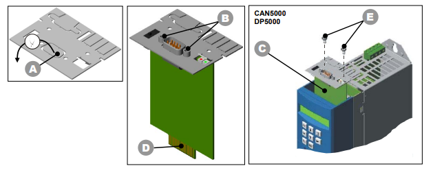
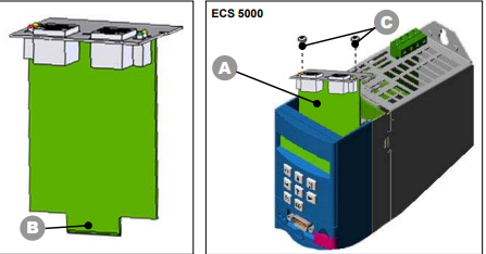
3.3.1.2 EtherCAT (ECS 5000)
• Make sure that the device is without power. Wait ≥ 5 min. for the DC link capacitors to discharge after turning off the power
supply voltage.
• Disconnect the cover plate by removing the two screws (C).
• Slide the EtherCAT board (A) with the gold-contacted terminal surfaces (B) into the black terminal block.
CAUTION
Be sure not to touch the gold contact surface with your fingers (danger of fouling and corrosion).
• Check correct position of the board.
• Secure the board with the two included screws (C).
• Then apply included labels (nameplate) to the cover plate.
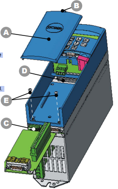
3.3.2 Option module 2 (terminals)
• Standard (SEA 5000, SEA 5001)
• Expanded (XEA 5001)
• Resolver (REA 5000)
Installation is the same for all modules.
• Make sure that the device is without power.
• Before installation, remove the blue plastic cover (A) below the serial interface
(terminal X3).
• Make sure that the device is without power.
• Unlock the snap-on lock (B) directly below terminal X3 and, on the snap-on
lock, pull the cover towards the front.
• To completely unhook the cover, pull this in the direction of the operator panel.
• Push the I/O terminal module with the gold-contacted terminal surface (C)
into the black terminal block (D).
CAUTION
Be sure not to touch the gold contact surface with your fingers
(danger of fouling and corrosion).
• Check correct position of the board.
• Secure the board with the two included screws (E).
• Now hook the plastic cover (A) with the two catches into the plastic housing.
• Press the plastic cover (A) against the plastic housing until the snap-on lock
(B) snaps in.
POSIDRIVE® MDS 5000 – Mounting Instructions STÖBER ANTRIEBSTECHNIK
4. Electrical Installation
15
4 ELECTRICAL INSTALLATION
This chapter gives you complete information on the subject of electrical installation.
Only specialized personnel who are qualified for this task may install, commission and control the device.
4.1 EMC
This chapter contains general information on EMC-suitable installation. These are only recommendations. Depending on the
application, the ambient conditions and the legal requirements, measures in addition to the following recommendations may be
required.
• Mount device or Bottom Brake Resistor on conductive surface (unpainted).
• Install the power cables in spatially separately from the signal lines (encoder, analog/digital signal lines).
• Use only shielded cable for motor lines (corresponding cabels can be ordered from STÖBER ANTRIEBSTECHNIK.).
• Apply shield of the motor cable over a large surface in the immediate vicinity of the MDS 5000. The EMC shield plate (EM
5000) for mounting on the bottom of the device is available as an accessory (see chap. 3.2.3 and chap. 7.1).
• With asynchronous machines, apply the shield to the terminal block over a large surface (e.g. PG shield screw connection).
• Use output deraters for motor lines > 50 m.
• When an additional transfer plug connector is to be installed in the motor cable, the cable shield may not be interrupted.
• When the brake line is installed in the motor cable, the brake line must be shielded separately.
• When the length of the cable for connection of a brake resistor is longer than 30 cm, this must be shielded and the shield
must be applied over a large surface in the immediate vicinity of the MDS 5000.
-
 HIRSCHMANN MSM20-M2M2M2M2SY9HH9E Ethernet media modul
 -
 HIRSCHMANN SPIDER-PL-20-05T1999999TWVHHHH Industrial Ethernet Rail Switch
 -
 Hirschmann SPIDER-PL-20-07T1M2M299TWVHHHH Industrial ETHERNET Rail Switch
 -
.png) Hirschmann (Belden) RS20-1600M2M2SDAEHC09.1.00 DIN-rail managed industrial Fast Ethernet switch
Hirschmann (Belden) RS20-1600M2M2SDAEHC09.1.00 DIN-rail managed industrial Fast Ethernet switch -
 Hirschmann (Belden) RS30-1602O6O6TDAPHC09.1.00 DIN-rail managed industrial Ethernet switch
 -
 Hirschmann (Belden) RS30-2402O6T1SDAPHH09.0.13 DIN-rail industrial Ethernet switch
 -
Hirschmann (Belden) SPIDER-PL-20-04T1S29999TY9HHHH Ethernet DIN-rail switch
-
 HIRSCHMANN RS20-1600T1T1SDAUHX Switch
 -
 HIRSCHMANN BRS42-0012OOOO-SPCZ99HHSES industrial switch
 -
 Hirschmann RS20-0800S2S2TDHPHH09.0.14 Fast Ethernet DIN rail switch.
 -
 HIRSCHMANN MM20-Z6Z6M2M2SAHH Hybrid Fast Ethernet Media Module
 -
 HIRSCHMANN MM20-Z6Z6T1T1SAHH hot-swappable hybrid Fast Ethernet Media Module
 -
 HIRSCHMANN MM20-P9P9T1T1SAHH Hybrid Fast Ethernet Media Module
 -
 HIRSCHMANN MM20-M4T1T1T1SAHH Hybrid Fast Ethernet Media Module
 -
 HIRSCHMANN MM20-M4M4T1T1SAHH Hybrid Fast Ethernet Media Module
 -
 HIRSCHMANN MM20-M2M2M2M2SZHH Ethernet media module
 -
HIRSCHMANN MM20-M2M2M2M2SAHH Ethernet media module
-
 HIRSCHMANN MM20-T1T1T1T1EBH 4-port Fast Ethernet Copper Cable Media Module
 -
HIRSCHMANN MM20-T1T1T1T1SAHH 4-port Fast Ethernet Copper Cable Media Module
-
HIRSCHMANN MM20-T1T1T1T1SAHH 4-port Fast Ethernet Copper Cable Media Module
-
 HIRSCHMANN MM20-Z6Z6EBH Hot-swappable fast Ethernet media module
 -
 HIRSCHMANN MM20-Z6Z6SAHH Ethernet media module
 -
HIRSCHMANN MM20-Z6Z6Z6Z6EBH Industrial Media Module
-
 MSM40-T1T1T1TZ9HH9E99.9.99 HIRSCHMANN Switch
 -
 HIRSCHMANN MS20-0800SAAEHC / MS20-0800SAAEHC0 8-port modular Layer 2 management Ethernet switch
 -
 Hirschmann RSPM20-4T14T1SZ9HHS9 Switch RSPM20-4T14T1SZ9HHS9
 -
 HIRSCHMANN RS20-1600M2M2SDAEHH09.1. RS20/30/40 Managed Switch configurator
 -
HIRSCHMANN RS20-1600M2M2SDAEHX09.0.00 Ethernet switch
-
 HIRSCHMANN BELDEN SPIDER-PL-20-07T1M2M299TY9HHHH / SPIDERPL2007T1M2M299TY9HHHH
 -
HIRSCHMANN MM3-1FXS2/3TX1 Switching Board Module
-
 HIRSCHMANN RSPE30-24044O7T99-ECCP999HHSE2A08.1.00 Industrial-grade fanless management-type Ethernet switch
 -
 HIRSCHMANN RS30-1602OOZZSDAEHC09.1.00 DIN-rail-mounted managed Layer 2 Ethernet switch
 -
 HIRSCHMANN MACH104-20TX-F Managed 24-port Full Gigabit 19" Switch
 -
 HIRSCHMANN Switch RS20-0800M4M4SDAE
 -
Hirschmann RS30-1602O6O6SDAEHH09.1. Management-type Ethernet switch
-
 Hirschmann RS30-1602OOZZSDAEHC09.0.10 Open rack-style Ethernet switch
 -
 HIRSCHMANN RSPE30-24044O7T99-SCCV999HHSI2SXX.X.XX High-Availability Seamless Redundancy
 -
HIRSCHMANN RSPE30-24044O7T99-SCCZ999HHSE2A DIN-rail Ethernet switch
-
HIRSCHMANN MM2-4TX1-EEC switch
-
HIRSCHMANN MSM40-T1T1T1T1TZ9HH9E99.9.99 Module
-
 HIRSCHMANN RS20 Rail Switch RS20-0400S4T1SDAEHC07.1.01
 -
 HIRSCHMANN M4-FAST8-SFP Fast Ethernet media module
 -
 HIRSCHMANN RS20-0400M2T1SDAP Managed Fast-Ethernet-Switch
 -
 HIRSCHMANN BELDEN SPIDER II 8TX/1FX EEC Industrial Ethernet Rail Switch
 -
HIRSCHMANN MM3-2FXS2/2TX1
-
 HIRSCHMANN RS2-4TX/1FX EEC Industrial Ethernet Rail Switch
 -
 RS30-0802O6O6SDAEHC09.0.10 HIRSCHMANN Switch
 -
 HIRSCHMANN m4-8TP-RJ45 Ethernet Media Module
 -
 HIRSCHMANN MSP30-24040SCZ9URHHE3A switch
 -
 Hirschmann rack MS30-1602SAAPHC
 -
 HIRSCHMANN RS2-FX/FX Industrial Switch Module
 -
Rs1txfx - Hirschmann - Rs1-Tx/Fx Rail Switch
-
RS20-0800S2S2SDAEHC09.1.00 HIRSCHMANN Commutator
-
 Hirschmann EAGLE20 TX/TX Industrial Security Router
 -
 Hirschmann SPIDER-SL-20-04T1S29999SY9HHHH Industrial Switch
 -
 HIRSCHMANN MAR1040-4C4C4C4C9999SMMHRHHXX.X. Gigabit Ethernet Switch configurator
 -
 Hirschmann MAR1040 Industrial Switch
 -
 HIRSCHMANN BELDEN RS30-1602O6O6SDAE
 -
Hirschmann RS20-1600M2M2SDAUHC Ethernet DIN rail switch
-
 HIRSCHMANN OCTOPUS 24M industrial switch
 -
 HIRSCHMANN RS20-1600T1T1SDAE Management-type Ethernet switch
 -
 HIRSCHMANN RS20-1600T1T1SDAUHH industrial switch
 -
HIRSCHMANN RS20-0800M2M2SDAPHC09.0.04 switch
-
 Hirschmann MR 8-03 24V DC Industrial Modular Bridge/Router
 -
 HIRSCHMANN RS20-0400M2T1SDAPHC08.0.01 Managed Switch
 -
 MACH1130 Hirschmann Industrial Switch
 -
 HIRSCHMANN 943824-002 SPIDER 5TX Industrial Ethernet Switch
 -
 HIRSCHMANN RS30-0802O6O6SDAEHC09.1.00 Managed Industrial Switch
 -
 HIRSCHMANN RS20-0400M2M2TDAEHC04.0.01 Industrial Switch
 -
 HIRSCHMANN BRS20-0600Z6Z6-STCZ99HHSES Industrial Switch
 -
 HIRSCHMANN MACH104-20TX-FR-L3P Industrial Ethernet Switch
 -
 HIRSCHMANN RS40-0009CCCCEDBPHH06.0.01 Industrial Switch
 -
 HIRSCHMANN RS2-3TX/2FX EEC Industrial Ethernet Switch
 -
 Hirschmann MACH 1020/1030 Fast/Gigabit Rack Mount Switches
 -
HIRSCHMANN RS20-0800M2M2SDAPHC09.0.14 Industrial Switch
-
 HIRSCHMANN RS20-1600T1T1SDAEHC09.0.04 Industrial Switch
 -
 HIRSCHMANN RSB20-0800T1T1EAABHH Industrial Switch
 -
 HIRSCHMANN MACH4002-48+4G-L3E Industrial Backbone Switch
 -
 HIRSCHMANN RS20-0400S2T1SDAE Industrial Managed Switch
 -
HIRSCHMANN RS20-0800S2T1SDAUHC Industrial Switch
-
 HIRSCHMANN RS20-2400S4S4SDAEHC09.0.14 industrial switch
 -
 HIRSCHMANN OS20-001200T5T5T5- TBBZ999HHNE3S 08.1.00 industrial switch
 -
HIRSCHMANN OS20-001200T5T5T5- TBBZ999HHNE3S 08.1.00 industrial switch
-
 HIRSCHMANN RS40-0009CCCCSDAEHH09.0.14 switch
 -
 Hirschmann RS20-1600T1T1SDAUHC Management-type Ethernet Switch
 -
 Hirschmann M1-8SFP Switche
 -
Hirschmann Industrial Ethernet Ruggedized Switch MACH1000 Family
-
 Basler Electric, Solid State Protective Relay, BE1-60
 -
BASLER ELECTRIC SR4A-2B15B3A Static Voltage Regulator
-
.png) BASLER ELECTRIC EXCITER DIODE MONITOR EDM-200
BASLER ELECTRIC EXCITER DIODE MONITOR EDM-200 -
.png) BASLER ELECTRIC DECS125-15-B2C5 DIGITAL EXCITATION CONTROL SYSTEM V 2.0.9
BASLER ELECTRIC DECS125-15-B2C5 DIGITAL EXCITATION CONTROL SYSTEM V 2.0.9 -
 BASLER ELECTRIC BE1-851 OVERCURRENT PROTECTION RELAY MECHANISM
 -
 Basler Electric BE1-51A / BE151A
 -
 Basler Electric BE1-40Q Loss of Excitation Relay
 -
 Basler Electric BE1-87G Variable Percentage Differential Relay
 -
 Basler Electric BE1-11 Protection System I5A3M2P2N0EA00
 -
 BASLER ELECTRIC DECS-200-1C Digital Excitation Control System
 -
 Basler Electric / Kohler BE1-11g Generator Protection Relay G5A3M2J2N0E000
 -
BASLER ELECTRIC DECS125-15 DIGITAL EXCITATION CONTROL SYSTEM
-
 BASLER ELECTRIC BE1-951 OverCurrent Protecton System
 -
Basler Electric DECS-200-1L Digital Excitation Control System
-
 Basler Electric DGC-2020HD-5NS1DNSBA Digital Genset Controller -
 -
 BASLER ELECTRIC BE1-81T1EE1WA0N1F / BE181T1EE1WA0N1F
 -
 BASLER ELECTRIC BE1-25M1EA6PN5R1F / BE125M1EA6PN5R1F
 -
 BASLER ELECTRIC DECS-250-LN1SN1N DIGITAL EXCITATION CONTROL SYSTEM
 -
Basler Electric DECS-250-CN2CN 1N Digital Excitation Control System Unit
-
 BASLER ELECTRIC DECS-300-C0N0 DIGITAL EXCITATION CONTROL SYSTEM
 -
 BASLER ELECTRIC BE1-87T-A1E-A1J-D0S1F / BE187TA1EA1JD0S1F
 -
BASLER ELECTRIC BE1-11-G6D1M0J2P0E000 Protection System
-
 BASLER ELECTRIC BE1-GPS100-E4N1H1N GENERATOR PROTECTION SYSTEM
 -
 Jaquet Relay card (Auxiliary module) FTV 3090 377Z-03985
 -
 Jaquet Trip Chain Control card FTBU 3034 377Z-05030
 -
 Jaquet with input card -E04 FTFU 3024 -E04 377Z-05855
 -
 Jaquet with input card -E03 FTFU 3024- E03 377Z-03983
 -
 Jaquet FTFU 3024- E02 377Z-03982 with input card -E02
 -
 Jaquet FTFU 3024-E01 377Z-03981 with input card -E01
 -
 Hirschmann RS20-2400T1T1SDAE Industrial Managed Ethernet Switch
 -
 Hirschmann BELDEN EAGLE30-04022O6TT999SCCV9HSE3F
 -
 Hirschmann MM3-2FXS2/2TX MICE Media Module
 -
 Hirschmann RS20-1600M2M2SDAPHC08.0.05 Industrial Managed Switch
 -
 Hirschmann OZD Profi 12M G12-1300 PRO Fieldbus Repeater
 -
Hirschmann SPIDER 4TX/1FX-ST EEC Industrial Ethernet Switch
-
 Hirschmann MM2-2FXM3/2TX1 MICE Media Module
 -
 Hirschmann RS20-2400M2M2SDAPHC09.0.14 Industrial Switch
 -
 Hirschmann RS20-0400M2M2SDAEHC07.1.05 OpenRail Switch
 -
 Hirschmann OZD Profi 12M G12-EEC Fieldbus Repeater
 -
HIRSCHMANN MDA422-1/2-3.5c-23/46 sensor
-
Hirschmann RS30-2402T1T1SDAUHC Managed Industrial Switch


