schneiderOperating Manual PacDrive™ C200 / C200 A2 Controller
stations) are connected to the signal voltage connectors of this component.
• Ensure that the existing electrical separation is maintained throughout the entire
circuit.
Failure to follow these instructions will result in death or serious injury
FELV Function‐
al Extra-Low
Voltage
When using ELAU Components in systems that do not have safe separation as a
protective measure against direct or indirect contact of dangerous voltages, all con‐
nections and contacts (e.g. PacDrive Controller, Sub-D connector, serial interface) that
do not meet protection class IP2X require a permanent cover. The cover or the device
connection of the connected device must be designed so that it can only be removed
by using a tool. The protective measures have to be adhered on all connected devices
Indicators, control elements, diagnosis
The PacDrive™ System supports the user with its comprehensive diagnostic sys‐
tem.
The diagnostic messages can be read out with the Automation Toolkit EPAS-4 . The
PacDrive™ System contains a powerful message logger in which additional diagnostic
information is recorded.
Diagnostic messages are usually displayed by a control panel on the machine. If an
"error" occurs, read the diagnostic message on this unit and then contact the machine
manufacturer.
Detailed information on diagnosis is available in the Online Help of the Automation
Toolkit EPAS-4.
3.1 Indicators on the PacDrive C200 Controller

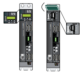
If the cover of the PacDrive Controller is closed, you will see four vertically arranged
indicators, which signal different operating- or error conditions.
• pow (control voltage indicator)
• wd (watchdog indicator)
• err (error display)
• bus err (SERCOS real-time bus error indicator)
V00.24.23
10.128.2111.103
0406-0117.0601
enter
In addition to the LED displays, you will receive further information about the operating
status of the PacDrive Controller via the 2-line LCD display.
Line 1 currently used firmware version
Line 2 current IP number of the PacDrive Controller
The horizontal arranged buttons have no function on the PacDrive Controller currently.
pow (control voltage display)
The "pow" LED indicates the state of the control voltage.
OFF The control voltage (24 V DC) is not available or too low.
ON Normal operation; control voltage in normal range
Flashes UPS active
wd (watchdog indicator)
Watchdog is a hardware module to monitor the controller.
OFF Normal operation
ON Fatal error; reset required, reboot system
A "fatal error" is a serious hardware problem or an unexpected software problem.
When a "fatal error" occurs
• the CPU is stopped,
• the optional module is reset,
• the outputs are reset and
• the wd (watchdog) relay outputs are opened.
err (error display)
The error LED (err) indicates errors. The following table lists the possible display con‐
ditions and their accompanying error descriptions.
OFF Normal operation
Flashes slowly (1.7 Hz) Error of class 1, 2, 3, 4 or 5 active
Flashes quickly (10 Hz) The boot of the PacDrive Controller is completed, the last boot failed.
See diagnostic message 209 "last boot failed". The PacDrive Controller
performed a minimal boot.
Flashes fast and slowly alter‐
nately
Firmware download via SERCOS is active
ON A serious error occurred during the current boot.
The err-LED is switched on following "Power on". Once the operating system, user
configuration, user parameters and the IEC program have been loaded and the IEC
program has been started successfully the err LED will switch off again. The boot
procedure is now complete.
bus err (SERCOS real-time bus error indicator)
OFF Normal operation
ON Bus error (problem with fiber-optic cable connection, e.g. transmitting
power is too low or too high, cable break, etc.)
Ethernet LEDs (data throughput indicator and network activity)
On the Ethernet connection (X10) of the PacDrive Controller two LED’s are indicated.
LED yellow: ON PacDrive Controller connected
LED yellow: flashing/flickering Current network traffic
LED yellow: OFF PacDrive Controller not connected
LED green: ON 100 MB connection
LED green: OFF 10 MB connection
After opening the operating cover you have access to the control elements of the Pac‐
Drive Controller:
• CompactFlashTM card slot
• Battery compartment
• [on / off] button
• [reset] button
3.2 CompactFlashTM card slot
The CompactFlash™ card slot is the entry for the permanent data memory (CF™ card)
of the PacDrive Controller.
▶ Switch off the PacDrive Controller.
▶ Hold the CF™ card with your thumb and forefinger and pull it out of the slot.
▶ To insert, carefully place the CF™ card on the guide rail and push it into the device.
▶ Push lightly until the card clicks in.
3.3 Battery compartment
battery
The battery of the PacDrive Controller buffers controller data (Bios, NVRAM, time,
etc.).
Maintenanceinterval
The battery should be replaced every 6 years. After this period of time the battery must
be replaced. If the device (with battery inserted) is not used for an extended period of
time, you should check/replace the battery.
Measurement This is how you measure the battery:
▶ Replace battery and continue with the manual measurement
or
▶ observe the diagnostic message "037 Battery down“ in the IEC program and dis‐


