
schneiderInstruction MI 021-390 February 2016 I/A Series® Magnetic Flow Transmitter Model IMT25 Operation, Configuration, and Calibration
1. Introduction
Description
An I/A Series Magnetic Flowmeter System consists of two major components:
IMT25 Magnetic Flow Transmitter with Version 2 Software
Magnetic Flowtube
8000A wafer body
2800, 8300, 9100A, 9200A, or 9300A flanged body
A system may be specified with the transmitter integrally mounted with the flowtube or with a
remote mounted transmitter, which can be mounted either on a pipe or a flat surface.
Your transmitter has one of three communication protocols.
One is a FoxCom communications protocol. The digital output signal in this version is used
for flowmeters serving as a primary measuring device in an I/A Series system. You can
communicate with this version via the I/A Series system, the PC-based Configurator, or the
optional local keypad/display.
Another has HART communications capability. You can communicate with this version via a
HART Communicator, PC-Based Configurator, or the optional local keypad/display.
The third has FOUNDATION fieldbus communication capability. You can communicate with
this version via a fieldbus host or the optional local keypad/display.
This document describes local operation, configuration, and calibration of an IMT25 Transmitter
supplied with local keypad and display. For information on operation, configuration, and
calibration from a PC-Based Configurator, a HART Communicator, or a FOUNDATION fieldbus
host refer to the documents listed in “Reference Documents” on page 13.
Intended Audience
This document is intended for use by process operators, engineers, and instrument technicians. If
you are interested only in operation, read the general information in the Introduction and the
chapter titled Operation. If you are interested in calibration, read the Introduction and chapters
titled Operation and Calibration. If you are concerned with configuration, read the entire manual,
with special emphasis on the chapter titles Configuration and the structure diagrams in
Appendix A and the configuration worksheets in Appendix B.
Functions
Using the IMT25 front panel keypad/display, the functions you can perform are:
Operating Functions
Display Measurement Information: The current value of the flow rate in engineering
units (EGU), flow rate in percent of upper range value (URV), the Forward Total,
Reverse Total, Net Total, and Grand Total.
Display the Status of the Transmitter: The current operating mode, Analog and Pulse
Output values, Contact Input settings, Relay Output settings, noise reduction,
AutoZeroLock information, and write protection as well as alarm and diagnostic
status.
Display Identity Information: Tag, description, and message plus identification data
for the flowmeter, flowtube, and transmitter software.
Acknowledge Alarms and Diagnostic Conditions.
Reset Totals.
Calibration Functions
NOTE
These functions can be passcode protected from keypad changes.
Adjust the 4 and 20 mA output signal (requires additional equipment)
Preset outputs to calibrate control loop
Calibrate the AutoZeroLock Detector
Configuration Functions
NOTE
These functions can be passcode protected from keypad changes.
Display and modify all configuration parameters
Assign passcodes and set levels of privilege
Reference Documents
This document addresses operation, configuration, and calibration using the local keypad/display
panel. For remote communication with your transmitter and other details of the flowmeter, refer
to the applicable documents listed in Table 1
2. Quick Start
FoxCom or HART Protocol
Your IMT25 Transmitter can be configured with a PC-Based Configurator or with the
keypad/display option. With the keypad/display, two configuration menus exist, Quick Start and
Setup. Most basic applications can be configured in Quick Start mode.
Quick Start mode can be used for applications requiring only:
A 4-20 mA output based on a flow rate in (US) GPM
The transmitter display to show a flow rate in (US) GPM
A FoxCom digital or HART flow rate signal.
Use Setup mode that is fully described in “Configuration” on page 39, for applications involving:
Transmitters powered from 50 Hz sources
Pulse and frequency outputs
Totalizer functions
Flow units other than (US) GPM
Alarm functions
Multi-range or bi-directional flow configurations.
To make Quick Start changes to the configuration, go to 1 TOP LEVEL/Quick Start by
pressing the Left arrow repeatedly until the display reads 1 TOP LEVEL. Then use the up/down
arrow keys to go to 1 TOP LEVEL/Quick Start. The procedure to change your configuration is
demonstrated by the following example:
Flowmeter factor of 18.22 (refer to “Determining the Meter Factor” on page 18)
Forward direction of flow
Flow Range 0 to 150 GPM
1. Use the Right arrow key to move to MFACTOR FORMAT? {###.######}. This format
can be changed, if necessary, to accommodate the meter factor.
a. If no change is required, press the Right arrow key.
b. To change the format, press Shift + Change to enter Edit Mode. Then use the
up/down arrow keys to step through the choices. When you reach the format you
want, press the Right arrow key.
2. The display reads METER FACTOR? {###.######} (Default {012.000000}). Press
Shift + Change to enter Edit Mode. Use the Right/Left arrow keys to move the
cursor under the digits you want to change. Use the up/down arrow keys to change
the digits to the desired values. In the case of this example, continue this procedure
until the display reads [018.220000]. Use the Right arrow key to move the cursor
out past the right bracket to save the setting. The display then reads METER FACTOR?
{018.219998}. Note that in some cases, as with this example, a slightly different
value will appear. The magnitude of this difference is insignificant. Press the Right
arrow key again.
NOTE
To determine the correct meter factor, refer to “Determining the Meter Factor” on
page 18.
3. The display reads RATE FORMAT? {#####.#} This format can be changed, if
necessary, to accommodate your flow rate.
a. If no change is required, press the Right arrow key.
b. To change the format, press Shift + Change to enter Edit Mode. Then use the
up/down arrow keys to step through the choices. When you reach the format you
want, press the Right arrow key.
4. The display reads FORWARD URV? {#####.#} (Default {00100.0}). Press Shift +
Change to enter Edit Mode. Use the Right/Left arrow keys to move the cursor under
the digits you want to change. Use the up/down arrow keys to change the digits to the
desired values. In the case of this example, continue this procedure until the display
reads [00150.0]. Use the Right arrow key to move the cursor out past the right
bracket to save the setting. The display then reads FORWARD URV? {00150.0}.
5. Now that all changes have been made, press the Right arrow key. You are asked Go
On-Line? Reply Yes by pressing the Right arrow key. Press the Right arrow key again
to begin displaying flow measurements.
Foundation Fieldbus Protocol
Your transmitter has been preconfigured at the factory to the settings shown in Appendix B.
Compare your needs to the factory configuration and note the changes to the configuration you
must make.
If the transmitter is not connected to a flowtube or IMTSIM, it is necessary to put a jumper wire
between terminals Coil 1 and Coil 2 and also to provide power to the transmitter.
This section describes the procedures to quick start the transmitter from the optional local
keypad/display. Note that after you quick start the transmitter from the local keypad, you should
use the fieldbus host to ensure that parameter values associated with the host are changed to agree
with those changed from the local keypad/display. Otherwise, mismatch errors occur when you
attempt to place the transmitter into Auto mode.
To make changes to the configuration using the local keypad/display, go to 1 TOP LEVEL/Setup
by pressing the Left arrow repeatedly until the display reads 1 TOP LEVEL. Then use the
Up/Down arrow keys to go to 1 TOP LEVEL/Setup. The procedure to change your
configuration is demonstrated by the following example:
Engineering units (EGUs) in GPM (factory default setting)
Forward direction of flow (Unidir positive - factory default setting)
Flow range 0 to 150 GPM
Flowmeter factor of 18.22 (refer to “Determining the Meter Factor” on page 18)
Note that the factory default engineering units is already configured as GPM, so no change is required. 2. Note that the factory Output mode is also already configured as UniDir positive, so no change in the direction is required. 3. You must enter your flow upper range value however. To do this: a. Go to Setup Level 2 by pressing the Right arrow key. Next move to 2 SETUP Outputs with the Down arrow key. Then move to 3 OUTPUTS Output Mode with the Right arrow key
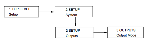
b. Use the Down arrow key to go to 3 OUTPUTS Range Info and the Right arrow
key to go to FORWARD URV? {#####.#} GPM (Default {00100.0}).
c. Press the Shift + Change keys to enter Edit mode. You are asked Go Offline?
Reply Yes by pressing the Right arrow key. The display shows FORWARD URV?
[#####.#] GPM.
d. Use the Right/Left arrow keys to move the cursor under the digits you want to
change. Use the Up/Down arrow keys to change the digits to the desired values. In
the case of this example, continue this procedure until the display reads
[00150.0].
e. Using the Right arrow key, move the cursor under the right bracket and press the
key to enter the URV. The display reads FORWARD URV? {150.0} GPM.
f. Press the key again to move back to 3 OUTPUTS Range Info.
4. Lastly, you have to enter your flowmeter factor. To do this:
a. Use the Left arrow key to move to the Level 2 menu, 2 SETUP Outputs.
b. Press the Down arrow key six times to move to 2 SETUP Calibration and the
Right arrow key to move to the Level 3 menu, 3 CALIBRATION Meter Factor.
See FIgure A-5.
c. Use the Right arrow key to move to MFACTOR FORMAT? {###.######}. This
format can be changed, if necessary, to accommodate the meter factor.
d. Use the Right arrow key to move to METER FACTOR? {###.######} (Default
{012.000000}. Then press Shift + Change to enter Edit mode.
e. Use the Right/Left arrow keys to move the cursor under the digits you want to
change. Use the Up/Down arrow keys to change the digits to the desired values. In
the case of this example, continue this procedure until the display reads
[018.220000]. Use the Right arrow key to move the cursor out past the right
bracket to save the setting. The display then reads METER FACTOR?
{018.219998}. Note that in some cases, as with this example, a slightly different
value appears. The magnitude of this difference is insignificant.
NOTE
To determine the correct meter factor, refer to “Determining the Meter Factor” on
page 18.
f. Press the Right arrow key again. The display reads 3 CALIBRATION Meter
Factor.
5. Now that all changes have been made, press the Left arrow key until you are asked Go
On-Line? Reply Yes by pressing the Right arrow key. To display flow measurement,
press the Right arrow key once more.
! CAUTION
If you change the upper range value or engineering units in the Transducer Block with
the local display pushbuttons without making a corresponding change in the
corresponding Analog Input Blocks from a fieldbus host, a mismatch error occurs and
the Analog Input Block reverts to Out of Service mode.
Determining the Meter Factor
First find the “Cal Factor” or “IMT25 Cal Fact” on the flowtube data label.
If the flowtube data label has a “IMT25 Cal Fact.” listing, use that value as the “Meter Factor.”
If only a “Cal Factor” value is found on the flowtube data label, that value must be multiplied by
the appropriate factor from Table 2 to calculate the “Meter Factor.”
Operation from Keypad/Display Panel
For local operation, configuration, and calibration, all operator entries are made through a
5-button keypad and all data is presented on a 2-line x 16 character LCD display. The
keypad/display of the IMT25 Transmitter is shown in Figure 1. Information on various types of
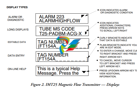
display is shown in Figure .
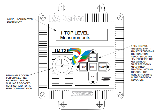
Figure 1. IMT25 Magnetic Flow Transmitter — Keypad/Display
All required functions are accomplished by using the four arrow keys alone and in combination
with the Shift key. Table 4 explains the function of each key
Top Level Menu
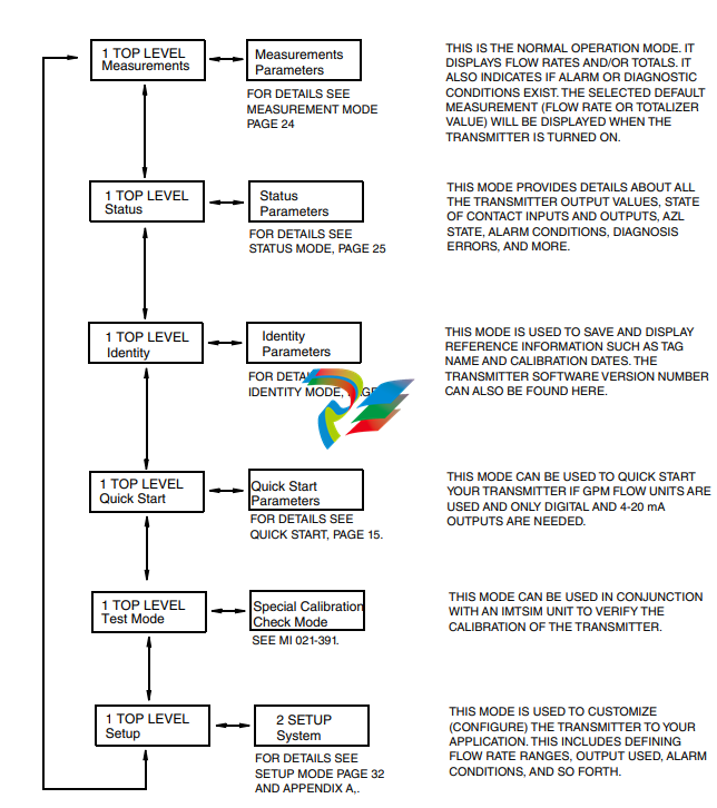
The Top Level menu displays the following modes – Measurements, Status, Identity, Quick Start
(in FoxCom and HART transmitters), Test Mode, and Setup. You can switch from one to another
in sequence by using the Up/Down arrow keys. To enter the second level menu from a particular
top level screen, press the Right arrow key. To return to the top level from a second level menu
item, press the Left arrow key. The level of the first, second, third, and fourth level menus is
indicated by the digit appearing as the first character in Line 1 of the display; a 1 indicates Level 1
(Top Level), a 2 indicates Level 2, and a 3 indicates Level 3, etc.
The top level menu is shown in Figure 3. For a complete presentation of all menu structures, refer
to Appendix A.
Measurements Mode
The Measurements mode, which is your main operating mode, is displayed upon startup.
Depending on the transmitter configuration, it has up to seven displays, any of which may be set
as the startup default. All screens can be scrolled with the Up/Down arrow keys.
Rate (EGU) — Shows current flow rate (forward or reverse) in the selected
engineering units.
Rate (% Range) — Shows current flow rate (forward or reverse) as a percentage of full
scale URV.
Fwd Tot — Shows current value of the forward totalized flow in engineering units.
Use the Net Tot display to reset.
Rev Tot — Shows current value of the reverse totalized flow in engineering units. Use
the Net Tot display to reset.
Net Tot — Shows current value of the net totalized flow (forward total - reverse total)
in selected engineering units. Press Shift + Reset to reset the displayed total to
zero. Resetting Net Tot also resets Fwd Tot and Rev Tot. It does not reset Gr Tot.
If Reset Totals is passcode protected, the message Enter Passcode appears.
Grand Tot — Shows current value of the grand total flow in engineering units. Press
Shift + Reset to reset the displayed total to zero. Resetting Gr Tot does not reset
Fwd Tot, Rev Tot, and Net Tot. If Reset Totals is passcode protected, the message
Enter Passcode appears.
If the Dual Display feature is configured On, a combination of two of these parameters can be
displayed at once. A typical dual display, in which Line 1 shows flow rate and Line 2 shows the
present forward total, is shown below. Units may not be displayed or may be truncated.
You may step through the displays of each of these parameters with the Up and Down arrow keys.
However, unless you specifically do so, the display defaults to that configured in Setup mode. The
engineering units and formats used in the displays are also configured in Setup mode.
Status Mode
The Status mode enables you to view fourteen system parameters and thus assess the performance
of the loop. You may not edit them in this mode. To step through the displays of the following
parameters, use the up/down arrow keys:
Mode — Shows the present operating mode: On-Line, Off-Line, Override, or
Calibrate. This will normally display On-Line. The other modes will only be
displayed if someone else has changed the mode with an I/A Series Workstation,
PC-Based Configurator, HART Communicator, or fieldbus host. Off-Line means
that it has been taken off-line; Override, that the measurements cannot be relied
upon because one or more of the outputs is at a preset value; and Calibrate, that the
transmitter is in Calibration mode.
Alarm — Shows the most current active alarm. If there are no active alarms but
something is in the history buffer, the display reads Alarms In Buffer. If there are
no active alarms and nothing in the buffer, display reads No Alarms.
Diagnostics — Shows No Diag, Diag Existed, or Diag Exists. If a diagnostic
problem exists, the second line identifies the problem. Help is available with the
Shift + Help keys. An active diagnostic problem cannot be cleared; the problem
must be corrected. Diag Existed means a diagnostic error did occur, but the
condition has cleared and the transmitter is working correctly. However, the Diag icon
will remain on the display until the diagnostic has been acknowledged. To clear, the
transmitter must be in the Status mode with the diag window displayed. Then use the
Shift + Ack keys.
Digital Output — If the transmitter output is in Digital Output mode, the display
shows whether the transmitter is configured for Unidirectional or BiDirectional flow.
If the transmitter is not in Digital Output mode, the screen is not displayed.
NOTE
Digital and Analog Output are mutually exclusive. Only one of the two are displayed
at any one time.
Analog Output — If the transmitter output is in Analog Output mode, the display
shows whether the transmitter is configured for U (unidirectional), U/M1
(unidirectional multirange-range 1), U/M2 (unidirectional multirange-range 2, U/M3
(unidirectional multirange-range 3), B/D (bidirectional dual range), or B/S
(bidirectional split range). If the transmitter is not in Analog Output mode, the screen
is not displayed.
NOTE
Digital and Analog Output are mutually exclusive. Only one of the two are displayed
at any one time.
Table 5. Analog Output Configuration
Display Interpretation
U UniDirectional Flow Single Range
U/M1 UniDirectional Flow Multi-Range
Range 1 Active
U/M2 UniDirectional Flow Multi-Range
Range 2 Active
U/M3 UniDirectional Flow Multi-Range
Range 3 Active
B/D BiDirectional Flow Dual Range
B/S BiDirectional Flow Split Range
(mA reading less than 12 indicates reverse flow, greater than 12,
positive flow)
**UNKNOWN** Multi-Range is configured, but both contact inputs used to select
the active range are in inactive state
AZL Detect (Empty Pipe Det) — The intent of the AutoZeroLock Detection
(Empty Pipe Detection) feature is explained in “AutoZeroLock (Empty Pipe)” on
page 53.
If the AutoZeroLock (Empty Pipe) detector is configured On, the display shows:
EPD Inactive, EPD Active, or EPD Needs Setpnt (FoxCom)
AZL Inactive, AZL Active, or AZL Needs Setpnt (HART)
Inactive, Active, or AZL Needs Cal (Fieldbus).
When AZL (EPD) is active, the outputs are locked at zero. If AZL (EPD) is
configured Off, the status display shows Off.
! WARNING
Do not take any action that can cause danger to personnel or damage to equipment
based on the assumption that a pipe is empty or full because of an AutoZeroLock
(Empty Pipe Detection) indication.
AZL Count (Empty Pipe Cnt) — Shows the cumulative count (maximum of 255) of
AZL (empty pipe) conditions that have occurred since the last reset. To reset the
count to zero, press Shift + Reset Note that in some cases several counts may
occur for one emptying of the pipeline.
Noise Reduction — Shows whether the noise reduction function is configured On or
Off.
Write Protection — Shows whether the Write Protection dip switch is in the On position so that
no Setup (configuration) changes may be made. This feature is usually only used in custody
transfer applications or for another reason that you want to assure that the configuration is not
changed. For the procedure to change the setting of this switch, see MI 021-387.
-
 HIRSCHMANN MSM20-M2M2M2M2SY9HH9E Ethernet media modul
 -
 HIRSCHMANN SPIDER-PL-20-05T1999999TWVHHHH Industrial Ethernet Rail Switch
 -
 Hirschmann SPIDER-PL-20-07T1M2M299TWVHHHH Industrial ETHERNET Rail Switch
 -
.png) Hirschmann (Belden) RS20-1600M2M2SDAEHC09.1.00 DIN-rail managed industrial Fast Ethernet switch
Hirschmann (Belden) RS20-1600M2M2SDAEHC09.1.00 DIN-rail managed industrial Fast Ethernet switch -
 Hirschmann (Belden) RS30-1602O6O6TDAPHC09.1.00 DIN-rail managed industrial Ethernet switch
 -
 Hirschmann (Belden) RS30-2402O6T1SDAPHH09.0.13 DIN-rail industrial Ethernet switch
 -
Hirschmann (Belden) SPIDER-PL-20-04T1S29999TY9HHHH Ethernet DIN-rail switch
-
 HIRSCHMANN RS20-1600T1T1SDAUHX Switch
 -
 HIRSCHMANN BRS42-0012OOOO-SPCZ99HHSES industrial switch
 -
 Hirschmann RS20-0800S2S2TDHPHH09.0.14 Fast Ethernet DIN rail switch.
 -
 HIRSCHMANN MM20-Z6Z6M2M2SAHH Hybrid Fast Ethernet Media Module
 -
 HIRSCHMANN MM20-Z6Z6T1T1SAHH hot-swappable hybrid Fast Ethernet Media Module
 -
 HIRSCHMANN MM20-P9P9T1T1SAHH Hybrid Fast Ethernet Media Module
 -
 HIRSCHMANN MM20-M4T1T1T1SAHH Hybrid Fast Ethernet Media Module
 -
 HIRSCHMANN MM20-M4M4T1T1SAHH Hybrid Fast Ethernet Media Module
 -
 HIRSCHMANN MM20-M2M2M2M2SZHH Ethernet media module
 -
HIRSCHMANN MM20-M2M2M2M2SAHH Ethernet media module
-
 HIRSCHMANN MM20-T1T1T1T1EBH 4-port Fast Ethernet Copper Cable Media Module
 -
HIRSCHMANN MM20-T1T1T1T1SAHH 4-port Fast Ethernet Copper Cable Media Module
-
HIRSCHMANN MM20-T1T1T1T1SAHH 4-port Fast Ethernet Copper Cable Media Module
-
 HIRSCHMANN MM20-Z6Z6EBH Hot-swappable fast Ethernet media module
 -
 HIRSCHMANN MM20-Z6Z6SAHH Ethernet media module
 -
HIRSCHMANN MM20-Z6Z6Z6Z6EBH Industrial Media Module
-
 MSM40-T1T1T1TZ9HH9E99.9.99 HIRSCHMANN Switch
 -
 HIRSCHMANN MS20-0800SAAEHC / MS20-0800SAAEHC0 8-port modular Layer 2 management Ethernet switch
 -
 Hirschmann RSPM20-4T14T1SZ9HHS9 Switch RSPM20-4T14T1SZ9HHS9
 -
 HIRSCHMANN RS20-1600M2M2SDAEHH09.1. RS20/30/40 Managed Switch configurator
 -
HIRSCHMANN RS20-1600M2M2SDAEHX09.0.00 Ethernet switch
-
 HIRSCHMANN BELDEN SPIDER-PL-20-07T1M2M299TY9HHHH / SPIDERPL2007T1M2M299TY9HHHH
 -
HIRSCHMANN MM3-1FXS2/3TX1 Switching Board Module
-
 HIRSCHMANN RSPE30-24044O7T99-ECCP999HHSE2A08.1.00 Industrial-grade fanless management-type Ethernet switch
 -
 HIRSCHMANN RS30-1602OOZZSDAEHC09.1.00 DIN-rail-mounted managed Layer 2 Ethernet switch
 -
 HIRSCHMANN MACH104-20TX-F Managed 24-port Full Gigabit 19" Switch
 -
 HIRSCHMANN Switch RS20-0800M4M4SDAE
 -
Hirschmann RS30-1602O6O6SDAEHH09.1. Management-type Ethernet switch
-
 Hirschmann RS30-1602OOZZSDAEHC09.0.10 Open rack-style Ethernet switch
 -
 HIRSCHMANN RSPE30-24044O7T99-SCCV999HHSI2SXX.X.XX High-Availability Seamless Redundancy
 -
HIRSCHMANN RSPE30-24044O7T99-SCCZ999HHSE2A DIN-rail Ethernet switch
-
HIRSCHMANN MM2-4TX1-EEC switch
-
HIRSCHMANN MSM40-T1T1T1T1TZ9HH9E99.9.99 Module
-
 HIRSCHMANN RS20 Rail Switch RS20-0400S4T1SDAEHC07.1.01
 -
 HIRSCHMANN M4-FAST8-SFP Fast Ethernet media module
 -
 HIRSCHMANN RS20-0400M2T1SDAP Managed Fast-Ethernet-Switch
 -
 HIRSCHMANN BELDEN SPIDER II 8TX/1FX EEC Industrial Ethernet Rail Switch
 -
HIRSCHMANN MM3-2FXS2/2TX1
-
 HIRSCHMANN RS2-4TX/1FX EEC Industrial Ethernet Rail Switch
 -
 RS30-0802O6O6SDAEHC09.0.10 HIRSCHMANN Switch
 -
 HIRSCHMANN m4-8TP-RJ45 Ethernet Media Module
 -
 HIRSCHMANN MSP30-24040SCZ9URHHE3A switch
 -
 Hirschmann rack MS30-1602SAAPHC
 -
 HIRSCHMANN RS2-FX/FX Industrial Switch Module
 -
Rs1txfx - Hirschmann - Rs1-Tx/Fx Rail Switch
-
RS20-0800S2S2SDAEHC09.1.00 HIRSCHMANN Commutator
-
 Hirschmann EAGLE20 TX/TX Industrial Security Router
 -
 Hirschmann SPIDER-SL-20-04T1S29999SY9HHHH Industrial Switch
 -
 HIRSCHMANN MAR1040-4C4C4C4C9999SMMHRHHXX.X. Gigabit Ethernet Switch configurator
 -
 Hirschmann MAR1040 Industrial Switch
 -
 HIRSCHMANN BELDEN RS30-1602O6O6SDAE
 -
Hirschmann RS20-1600M2M2SDAUHC Ethernet DIN rail switch
-
 HIRSCHMANN OCTOPUS 24M industrial switch
 -
 HIRSCHMANN RS20-1600T1T1SDAE Management-type Ethernet switch
 -
 HIRSCHMANN RS20-1600T1T1SDAUHH industrial switch
 -
HIRSCHMANN RS20-0800M2M2SDAPHC09.0.04 switch
-
 Hirschmann MR 8-03 24V DC Industrial Modular Bridge/Router
 -
 HIRSCHMANN RS20-0400M2T1SDAPHC08.0.01 Managed Switch
 -
 MACH1130 Hirschmann Industrial Switch
 -
 HIRSCHMANN 943824-002 SPIDER 5TX Industrial Ethernet Switch
 -
 HIRSCHMANN RS30-0802O6O6SDAEHC09.1.00 Managed Industrial Switch
 -
 HIRSCHMANN RS20-0400M2M2TDAEHC04.0.01 Industrial Switch
 -
 HIRSCHMANN BRS20-0600Z6Z6-STCZ99HHSES Industrial Switch
 -
 HIRSCHMANN MACH104-20TX-FR-L3P Industrial Ethernet Switch
 -
 HIRSCHMANN RS40-0009CCCCEDBPHH06.0.01 Industrial Switch
 -
 HIRSCHMANN RS2-3TX/2FX EEC Industrial Ethernet Switch
 -
 Hirschmann MACH 1020/1030 Fast/Gigabit Rack Mount Switches
 -
HIRSCHMANN RS20-0800M2M2SDAPHC09.0.14 Industrial Switch
-
 HIRSCHMANN RS20-1600T1T1SDAEHC09.0.04 Industrial Switch
 -
 HIRSCHMANN RSB20-0800T1T1EAABHH Industrial Switch
 -
 HIRSCHMANN MACH4002-48+4G-L3E Industrial Backbone Switch
 -
 HIRSCHMANN RS20-0400S2T1SDAE Industrial Managed Switch
 -
HIRSCHMANN RS20-0800S2T1SDAUHC Industrial Switch
-
 HIRSCHMANN RS20-2400S4S4SDAEHC09.0.14 industrial switch
 -
 HIRSCHMANN OS20-001200T5T5T5- TBBZ999HHNE3S 08.1.00 industrial switch
 -
HIRSCHMANN OS20-001200T5T5T5- TBBZ999HHNE3S 08.1.00 industrial switch
-
 HIRSCHMANN RS40-0009CCCCSDAEHH09.0.14 switch
 -
 Hirschmann RS20-1600T1T1SDAUHC Management-type Ethernet Switch
 -
 Hirschmann M1-8SFP Switche
 -
Hirschmann Industrial Ethernet Ruggedized Switch MACH1000 Family
-
 Basler Electric, Solid State Protective Relay, BE1-60
 -
BASLER ELECTRIC SR4A-2B15B3A Static Voltage Regulator
-
.png) BASLER ELECTRIC EXCITER DIODE MONITOR EDM-200
BASLER ELECTRIC EXCITER DIODE MONITOR EDM-200 -
.png) BASLER ELECTRIC DECS125-15-B2C5 DIGITAL EXCITATION CONTROL SYSTEM V 2.0.9
BASLER ELECTRIC DECS125-15-B2C5 DIGITAL EXCITATION CONTROL SYSTEM V 2.0.9 -
 BASLER ELECTRIC BE1-851 OVERCURRENT PROTECTION RELAY MECHANISM
 -
 Basler Electric BE1-51A / BE151A
 -
 Basler Electric BE1-40Q Loss of Excitation Relay
 -
 Basler Electric BE1-87G Variable Percentage Differential Relay
 -
 Basler Electric BE1-11 Protection System I5A3M2P2N0EA00
 -
 BASLER ELECTRIC DECS-200-1C Digital Excitation Control System
 -
 Basler Electric / Kohler BE1-11g Generator Protection Relay G5A3M2J2N0E000
 -
BASLER ELECTRIC DECS125-15 DIGITAL EXCITATION CONTROL SYSTEM
-
 BASLER ELECTRIC BE1-951 OverCurrent Protecton System
 -
Basler Electric DECS-200-1L Digital Excitation Control System
-
 Basler Electric DGC-2020HD-5NS1DNSBA Digital Genset Controller -
 -
 BASLER ELECTRIC BE1-81T1EE1WA0N1F / BE181T1EE1WA0N1F
 -
 BASLER ELECTRIC BE1-25M1EA6PN5R1F / BE125M1EA6PN5R1F
 -
 BASLER ELECTRIC DECS-250-LN1SN1N DIGITAL EXCITATION CONTROL SYSTEM
 -
Basler Electric DECS-250-CN2CN 1N Digital Excitation Control System Unit
-
 BASLER ELECTRIC DECS-300-C0N0 DIGITAL EXCITATION CONTROL SYSTEM
 -
 BASLER ELECTRIC BE1-87T-A1E-A1J-D0S1F / BE187TA1EA1JD0S1F
 -
BASLER ELECTRIC BE1-11-G6D1M0J2P0E000 Protection System
-
 BASLER ELECTRIC BE1-GPS100-E4N1H1N GENERATOR PROTECTION SYSTEM
 -
 Jaquet Relay card (Auxiliary module) FTV 3090 377Z-03985
 -
 Jaquet Trip Chain Control card FTBU 3034 377Z-05030
 -
 Jaquet with input card -E04 FTFU 3024 -E04 377Z-05855
 -
 Jaquet with input card -E03 FTFU 3024- E03 377Z-03983
 -
 Jaquet FTFU 3024- E02 377Z-03982 with input card -E02
 -
 Jaquet FTFU 3024-E01 377Z-03981 with input card -E01
 -
 Hirschmann RS20-2400T1T1SDAE Industrial Managed Ethernet Switch
 -
 Hirschmann BELDEN EAGLE30-04022O6TT999SCCV9HSE3F
 -
 Hirschmann MM3-2FXS2/2TX MICE Media Module
 -
 Hirschmann RS20-1600M2M2SDAPHC08.0.05 Industrial Managed Switch
 -
 Hirschmann OZD Profi 12M G12-1300 PRO Fieldbus Repeater
 -
Hirschmann SPIDER 4TX/1FX-ST EEC Industrial Ethernet Switch
-
 Hirschmann MM2-2FXM3/2TX1 MICE Media Module
 -
 Hirschmann RS20-2400M2M2SDAPHC09.0.14 Industrial Switch
 -
 Hirschmann RS20-0400M2M2SDAEHC07.1.05 OpenRail Switch
 -
 Hirschmann OZD Profi 12M G12-EEC Fieldbus Repeater
 -
HIRSCHMANN MDA422-1/2-3.5c-23/46 sensor
-
Hirschmann RS30-2402T1T1SDAUHC Managed Industrial Switch


