
schneiderInstruction B0123HF and B0123HE Pressure Regulators and B1279UL Air Filter
Introduction
These regulators provide controlled air service to pneumatic instruments. The regulator regulates
a maximum supply pressure of 1.7 MPa (250 psi, 17 bar or kg/cm2) to the nominal levels required
by pneumatic instrumentation.
General
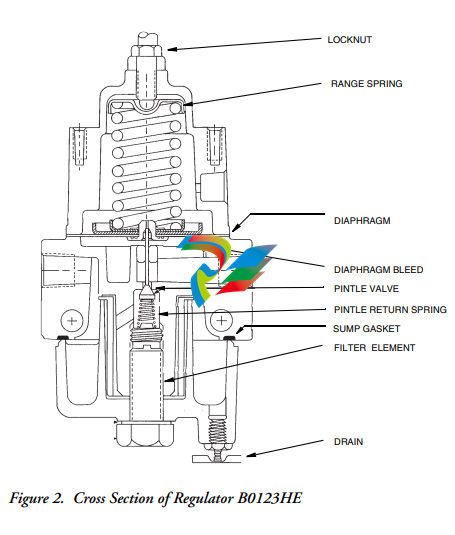
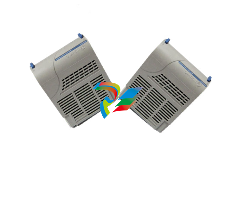
The B0123HF and B0123HE regulators have identical control ranges and are similar in
construction, except that the B0123HE has an integral filter element and drain feature.
Specifications
Installation
Part No. B0123HF Regulator
Refer to DP 011-158 for overall dimensions. The B0123HF can be supported by the supply and
regulated line piping, or panel mounted. Panel mounting is accomplished by utilizing the two
0.190-24 tapped holes in the top of the regulator. When installing regulator, care should be taken
that the IN and OUT ports are correctly oriented for the piping.
Part No. B0123HE Regulator
Refer to DP 011-157 for overall dimensions. The regulator should be installed as near as possible
to the instrument it is to service. It can be installed either vertically or horizontally, provided the
drain remains located at the lowest point on the assembly. The regulator has two
8 mm (0.320in) diameter holes passing entirely through the body for mounting on a suitable
bracket, or it can be supported by the supply and regulated line piping. It also has two
0.190-24 tapped holes in the body for mounting to a panel.
Operation
To increase pressure, turn the regulator adjustment knob in a clockwise direction. To decrease
pressure, turn the adjustment knob in a counterclockwise direction.
Supply Pressure 1.7 MPa (250 psi, 17 bat or kg/cm2)
Flow Capacity at 700 kPa
(100 psi, 7 bar or kg/cm2)
supply. Regulated to 140 kPa
(20 psi, 1.4 bar or kg/cm2)
33.6 m3
/hr
Sensitivity 25 mmH2O (1 inH2O)
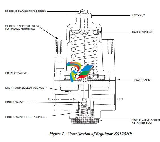
Principle of Operation
(Refer to Figure 1 and Figure 2.)
The range spring, which has been compressed by the adjustment knob and screw, causes the
pintle valve to move downward, allowing air to flow. The pressure builds up against the
diaphragm until the pintle valve throttles. This is the set pressure which is closely maintained in
the following manner: A drop in the regulated line pressure will cause a decrease in the pressure
against the bottom of the diaphragm. The range spring forces the diaphragm down against the
reduced pressure causing the pintle valve to open, admitting more supply air, until the pressure
below the diaphragm balances the spring force. Diaphragm upward motion causes the exhaust
valve in the diaphragm to open. The excess pressure rises into the spring cavity through the
exhaust valve and vents to atmosphere via the exhaust vent.
Maintenance
To install normally replaced parts, the following procedures should be followed.
! CAUTION
Before removing the four cover screws, turn pressure adjusting screw (knob)
counterclockwise on the range spring.
Part No. B0123HF Regulator
1. Remove cover and clean all parts thoroughly.
2. Replace diaphragm and reassemble top assembly.
3. Invert the top assembly and install pintle valve and valve return spring.
Use repair kit, Part No. B0127VS, available from Foxboro. This kit contains a
replacement diaphragm and a pintle valve and spring. Replace air screen and plug
gasket using repair kit, Part No. B0127VV.
Part No. B0123HE Regulator
Periodic cleaning of the filter element is recommended. Shut off the air supply and drain
condensate.
1. Remove the large bolt from the bottom of the regulator and remove sump.
2. Lift out the filter element. Clean all parts thoroughly and reassemble in reverse order
of removal.
Repair Kit, Part No. B0127VS, available from Foxboro, contains a replacement
diaphragm and a pintle valve and spring. Repair Kit, Part no. B0127VT, contains a
resealing gasket, sump bolt washer, and a replacement drain valve.
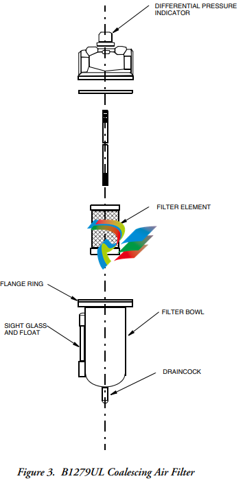
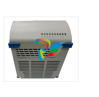
Part No. B1279UL Air Filter
Filter Element Replacement
To replace the filter element, relieve all air pressure from the filter. Unscrew flange ring
(counterclockwise from the bottom), and remove bowl. Remove the bottom adapter and the filter
element. To reassemble, install adapter bottom adapter, bowl, and flange ring,
.
Draining Instructions
To drain, turn draincock on bottom of bowl clockwise from bottom until all liquid is drained,
Turn draincock counterclockwise from bottom to reseal.
Differential Pressure Indicator
When the pressure drop across the filter element reaches 10-12 psi, the red indicators will be in
full view and the element should be replaced. Failure to replace the element when the pressure
drop exceeds 10 psi can be costly, both in terms of reduced air quality due to contaminant reentrapment and the power cost associated with forcing compressed air through an obstructed
filter.
-
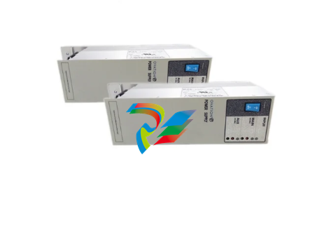
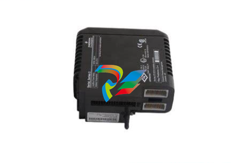
 EMERSON VE3008 CE3008 KJ2005X1-MQ1 12P6381X042 MQ Controller
 -
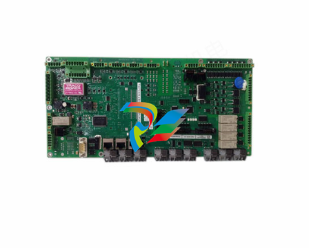
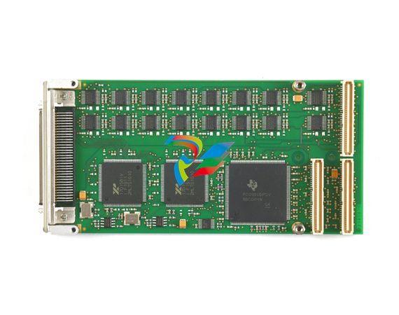
EMERSON TPMC917 4MB SRAM with Battery Backup and 4 Channel RS232
-
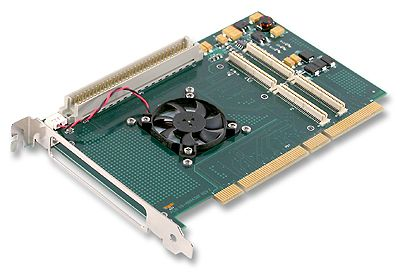
 EMERSON P152.R4 Multifunctional module
 -
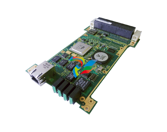
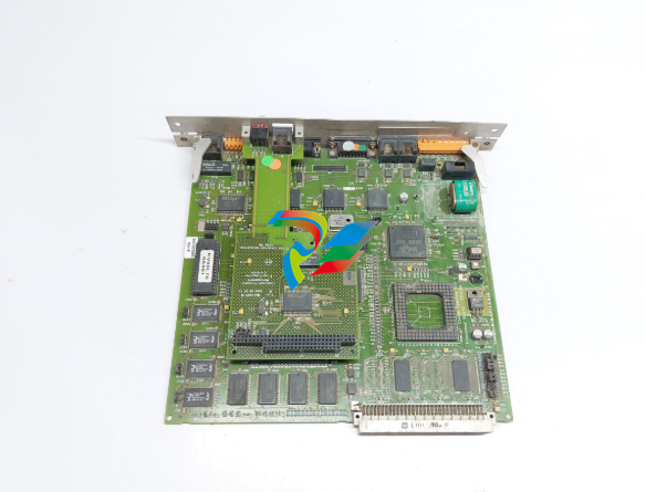 EMERSON DA7281520 P152 Processor board
 -
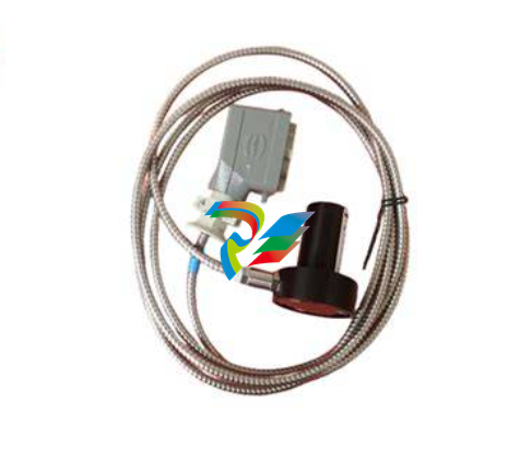 EMERSON PR6423/008-110 8mm Eddy Current Sensor
 -
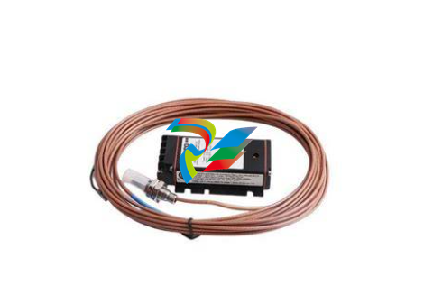 EMERSON PR6423/000-131 8mm Eddy Current Sensor
 -
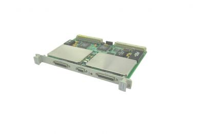
 EMERSON MVME61006E-0163R VMEbus Single-Board Computer
 -
 EMERSON Ovation 5X00453G01 Remote I/O Node Controller Module
 -
EMERSON 5X00070G04 Analog input
-
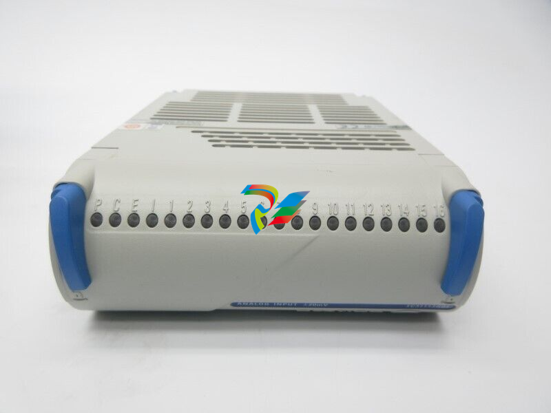
 EMERSON Ovation 5X00070G01 Analog Input Module
 -
 EMERSON Ovation 5X00790G01 Compact Controller Module
 -
 EMERSON 5X00846G01 HART analog output module
 -
 EMERSON 1C31113G01 Digital output module (5-60VDC)
 -
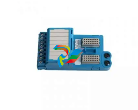 EMERSON KJ4110X1-BA1 I/O terminal module
 -
 EMERSON CSI3125 A3125/022-020 Shaft-Vibration Monitor
 -
 EMERSON 5X00273G01 Digital output module
 -
 EMERSON KJ4001X1-NB1 12P3368X012 REV:E 1-Wide I/O Carrier Extender Left
 -
 EMERSON KJ4001X1-NA1 12P3373X012 REV:C 1-Wide I/O Carrier Extender Right
 -
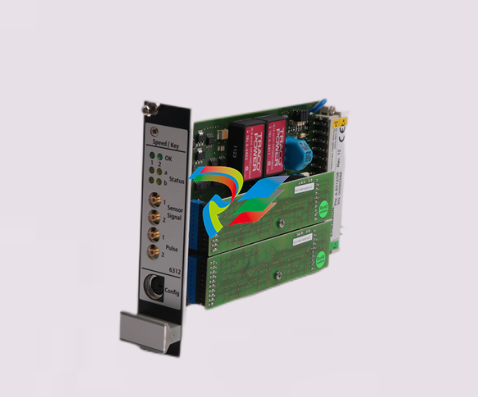 EMERSON A6312/06 Speed and Key Monitor
 -
 EMERSON KJ4001X1-BE1 8-Wide I/O Carrier
 -
 EMERSON KJ2005X1-MQ1 KJ2005X1-MQ2 13P0072X082 MQ Controller
 -
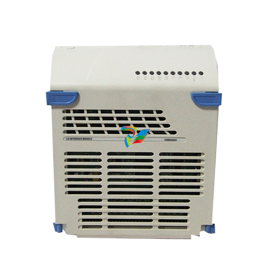
 EMERSON 5X00226G03 - Ovation™ I/O Interface Controller, Electronics Module
 -
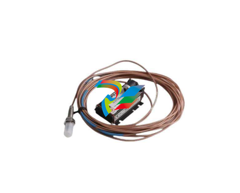
 EMERSON PR6423/00R-010+CON031 Vibration sensor
 -
 EMERSON 9199-00002 A6120 Control Module
 -
 Emerson Ovation 1C31234G01 - Ovation™ 16 Channel Compact Digital Input
 -
 Emerson Ovation KJ3002X1-BF1 12P1732X042 Controller module
 -
 Emerson Ovation 5X00226G01 I/O Interface Module
 -
 Emerson Ovation™ Controller Model OCR1100(5X00481G04/5X00226G04)
 -
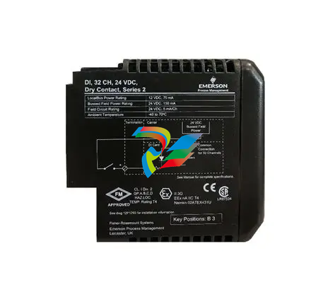
 Emerson Ovation 5X00499G01 Digital Input 24Vdc Single 32CH
 -
 Emerson Ovation 5X00500G01 32-Channel Digital Output Module
 -
 Emerson ovation VE4001S2T2B4 Analog output card
 -
 Emerson ovation 5X00501G01 5X00502G01 Ethernet link controller
 -
 EMERSON A6824R 9199-00098-13 Module
 -
 EMERSON A6140 9199-00058 Industrial Control Module
 -
 EMERSON 1C31194G03 Industrial Control Module
 -
 EMERSON DB1-1 Industrial Control Module
 -
 EMERSON PMC-IO-ADAPTER I/O module
 -
 EMERSON L0115012 L0115032 Control module
 -
 EMERSON PMC-IO-PROZESSOR Process control module
 -
 EMERSON PMC PROFINET Manage Gigabit Ethernet switches
 -
 EMERSON A3120022-000 CSI3120 Bearing-Vibration Monitor
 -
 EMERSON SE3008 KJ2005X1-SQ1 12P6383X032 Controller
 -
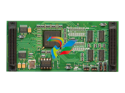
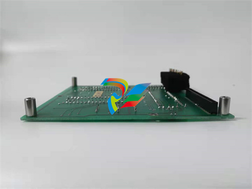 EMERSON 1000554 Printed circuit board
 -
 EMERSON PR6423/002-041 Sensor module
 -
 EMERSON 1C31232G02 Westinghouse control module
 -
 Abaco TRRM940 Switch
 -
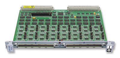
 Abaco SWE440A Switch
 -
 Abaco NETernity™ RM984RC Ethernet Switch
 -
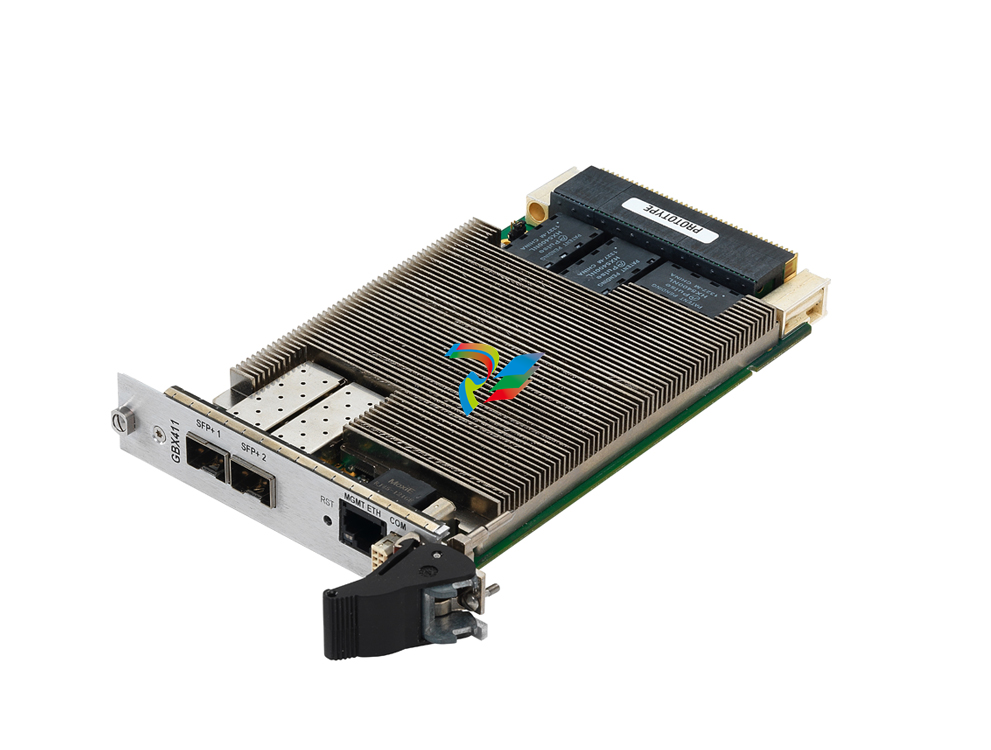 Abaco NETernity™ GBX411 Ethernet Switch
 -
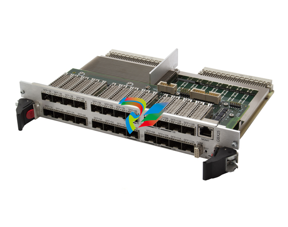 Abaco NETernity™ GBX25
 -
 Abaco NETernity SWE540A
 -
 Abaco CP3-GESW8-TM8 Ethernet switch
 -
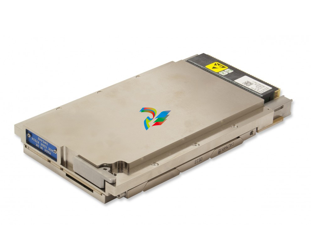
 Abaco SWE440S Ethernet switch
 -
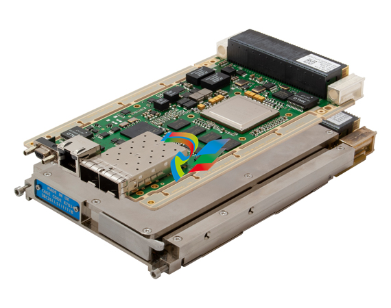
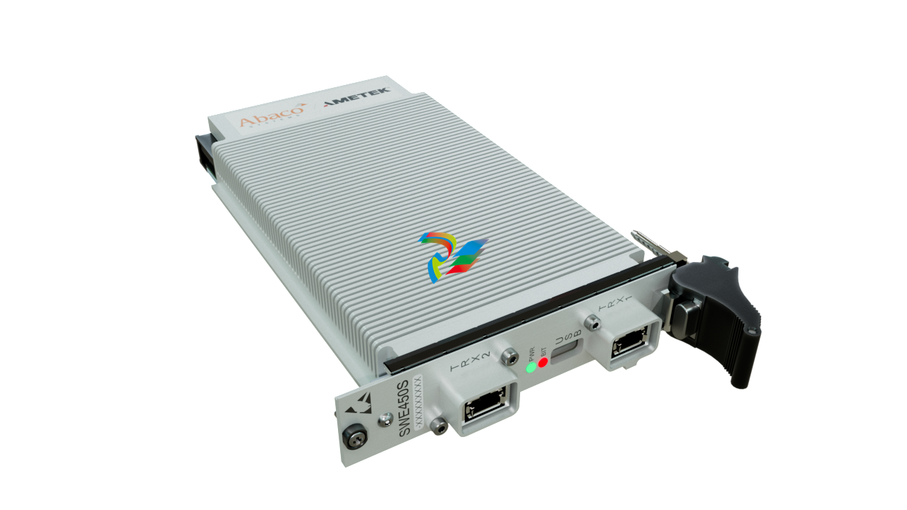 Abaco SWE450S 100GbE 3U VPX Switch Aligned to SOSA™ Standard
 -
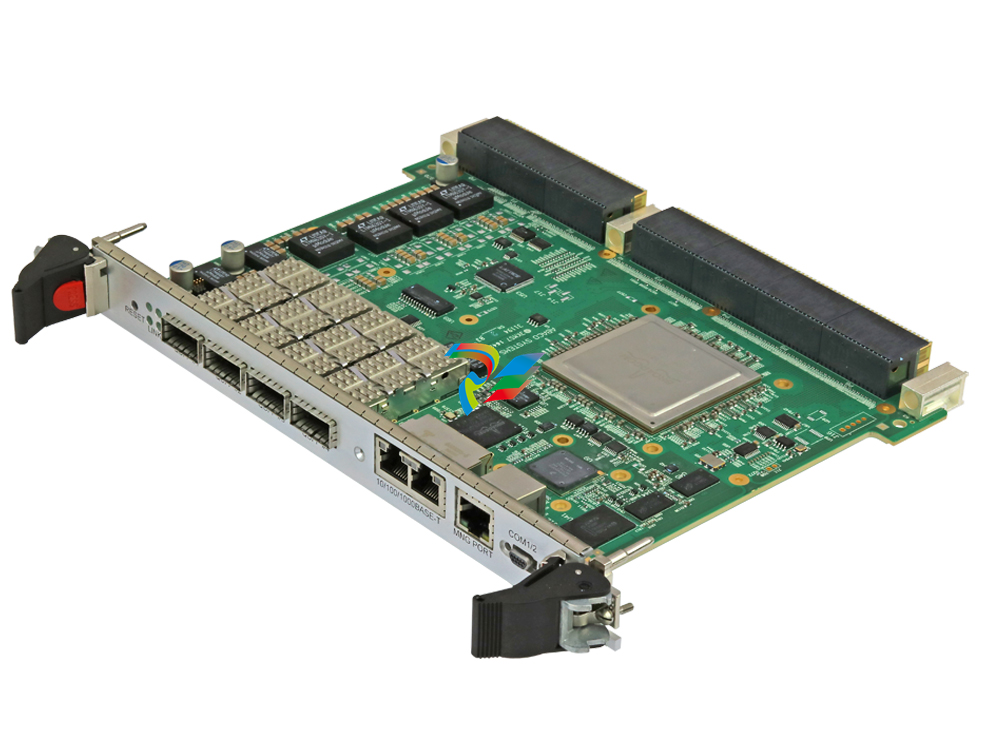
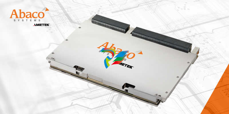 Abaco SWE550S 100GbE 6U VPX Switch Aligned to SOSA™ Standard
 -
 Abaco SPR870A Wideband Digital Receiver/Exciter
 -
 Abaco SPR507B Serial FPDP XMC/PMC
 -
 Abaco ICS-1572A Transceiver Module
 -
 Abaco daq8580 FMV Compression System
 -
 Abaco VP868 FPGA Card
 -
 Abaco HPC2812 Rugged 6U VPX High Performance Computer with Dual Intel
 -
 Abaco VSR347D 3U VPX Rugged Virtual Secure Router
 -
 Abaco VSR8000 Fully Rugged, COTS System Secure Router
 -
 Abaco RES3000 Compact, Rugged Ethernet Switches
 -
 Abaco PMC238 Expansion Card
 -
 Abaco EXP238 PMC/XMC Expansion Card for XVB603 VME Single Board Computer
 -
 Abaco VME-REPEAT-A-L VMEbus Repeater Link
 -
 Abaco VME-4514A VME Analog I/O Input/Output Board
 -
 Abaco VME-3128A Analog I/O
 -
 Abaco VME-3125A analog-to-digital Conversion board
 -
 Abaco VME-3123A VME Analog I/O Input Boards
 -
 Abaco PMC239/F Analog input/output board
 -
 Abaco PEX431 Multi-fabric Switch
 -
 Abaco CPCI-100A-BP 2-slot IndustryPack carrier for 3U CompactPCI
 -
 Abaco PMC522 Serial Controller
 -
 Abaco PMC522/FP Serial Controller
 -
 Abaco VME-2170A Digital Output 32-bit optically isolated
 -
Abaco VME-1129 Digital Input Board 128-bit high voltage
-
 Abaco IP-OCTALPLUS232 Eight EIA-232 asynchronous serial ports
 -
 Abaco IP-DIGITAL482 Digital I/O with 48 TTL Channels
 -
 Abaco PMC523 16-Port Serial Controller
 -
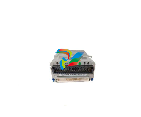
 EMERSON CE4003S2B1 M-series Traditional I/O
 -
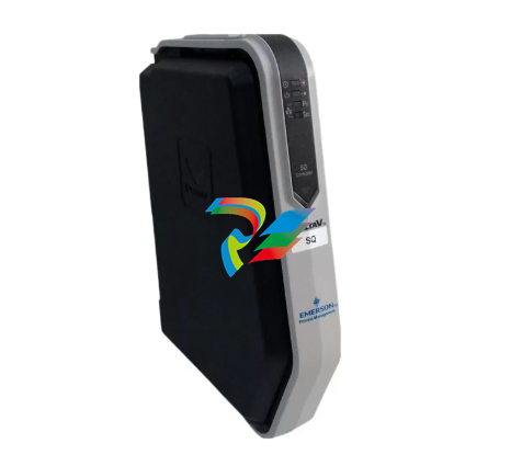
 EMERSON SE3008 DeltaV™ SQ Controller
 -
EMERSON 1C31227G01 - Ovation™ 8 Channel Analog Input
-
EMERSON 1C31224G01 - Ovation™ 8 Channel Analog Input
-
 ABB UNS0119A-P,V101 3BHE029154P3 3BHE029153R0101 Digital input
 -
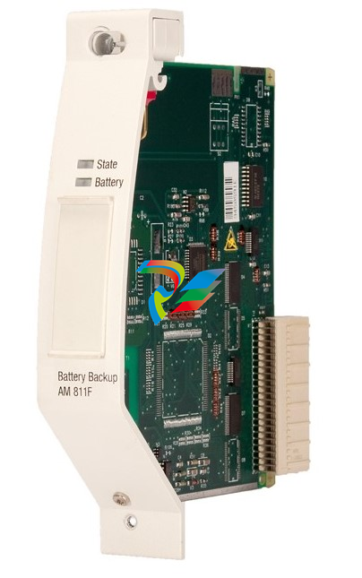 ABB 3BDH000050R1 AM811F Battery Module
 -
 ABB 3ASC25H705-7 Digital output board
 -
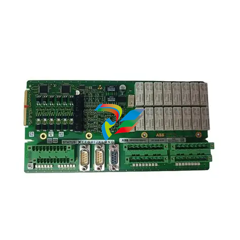 ABB UDD406A 3BHE041465P201 control board
 -
 ABB 3BHE014967R0002 UNS 2880B-P,V2: COB PCB Assembled
 -
 ABB PPC380AE02 HIEE300885R0102 module
 -
 ABB NU8976A99 HIER466665R0099 Processor Module
 -
 ABB DIS0006 2RAA005802A0003G Digital Input Module
 -
 ABB Bailey IMDS003 infi 90 Digital Output Slave Module
 -
 ABB XO08R1-B4.0 Expand the output relay module
 -
 ABB VA-MC15-05 Controller module
 -
 ABB VA-3180-10 Controller module
 -
 ABB 72395-4-0399123 Excitation module
 -
 ABB PU516A 3BSE032402R1 Engineering Board - PCI
 -
 ABB 3BHE044481R0101 3BHE044477P3 PPE091A101 Module
 -
 ABB UCD224A102 Control unit
 -
 ABB SNAT603CNT SNAT 603 CNT Motor Control Board
 -
 ABB SNAT634PAC Drive board
 -
 ABB UAD149A0011 Servo controller
 -
ABB UCD224A103 Industrial controller module
-
 ABB 3BHE029154P3/3BHE029153R0101 UNS0119A-P,V101 Processor Module
 -
 ABB ARCOL 0338 ARCOL 0346 Solid-state motor starter
 -
 ABB ARCOL 0339 Solid-state motor controller
 -
 ABB KUC720AE01 3BHB003431R0001 3BHB000652R0001 power control drive board card
 -
 ABB UFC718AE01 HIEE300936R0101 Main Circuit Interface Board
 -
 ABB 216DB61 HESG324063R100 Input/output and trip unit module
 -
 ABB 3HAC17973-1 DSQC332A I/O Unit
 -
 ABB DSQC509 Circuit board connection unit
 -
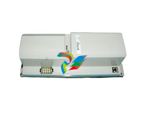 ABB DSQC346B Control module
 -
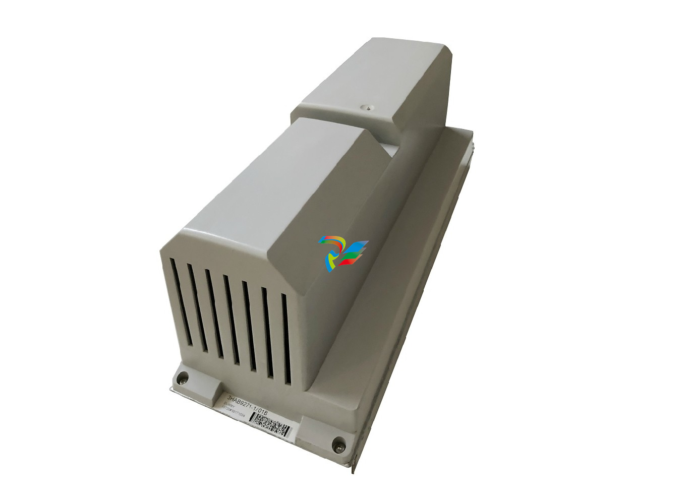 ABB 3HAB9271-1 Dummy Module Drive System
 -
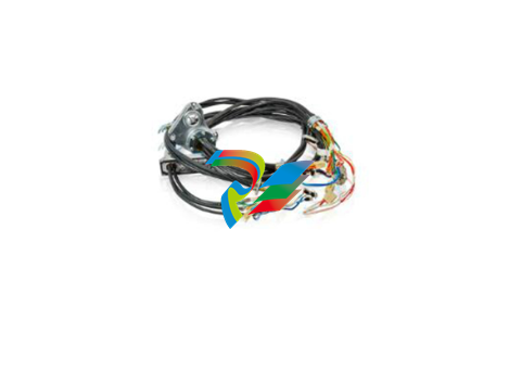 ABB 3HAC5566-1 Robot drive system cable
 -
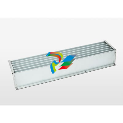 ABB 3HAC9710-1 Heat exchanger unit
 -
 ABB SPBLK01 Blank Faceplate
 -
 ABB IMFECI2 Multifunctional control board
 -
 ABB IMDSO14 ,Digital Slave Output Module
 -
 ABB 3HAC031683-004 Cable Teach Pendant 30m
 -
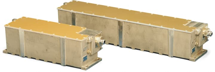 ABB Millmate Strip Scanner Edge Sensor PMSG12x
 -
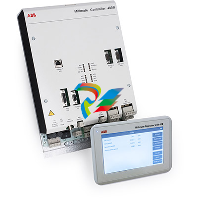 ABB Millmate Controller 400 PFXA401SF
 -
 ABB UAC318AE Controller module
 -
 ABB UNS2980c-ZV4 Medium-voltage control mainboard
 -
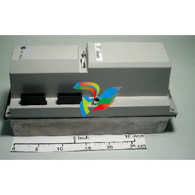 ABB 3ASC25H204 DAPU100 Control board, I/O
 -
ABB 3HAB8101-19 DSQC545A Modules Drive System
-
 ABB CP-E 24/1.25 Power supply


