
ABBAC 800M Controller Hardware Product Guide
NOTICE
This document contains information about one or more ABB products and may include a
description of or a reference to one or more standards that may be generally relevant to
the ABB products. The presence of any such description of a standard or reference to a
standard is not a representation that all of the ABB products referenced in this document
support all of the features of the described or referenced standard. In order to determine
the specific features supported by a particular ABB product, the reader should consult the
product specifications for the particular ABB product.
ABB may have one or more patents or pending patent applications protecting the intellectual property in the ABB products described in this document.
The information in this document is subject to change without notice and should not be
construed as a commitment by ABB. ABB assumes no responsibility for any errors that
may appear in this document.
In no event shall ABB be liable for direct, indirect, special, incidental or consequential
damages of any nature or kind arising from the use of this document, nor shall ABB be
liable for incidental or consequential damages arising from use of any software or hardware described in this document.
This document and parts thereof must not be reproduced or copied without written permission from ABB, and the contents thereof must not be imparted to a third party nor used
for any unauthorized purpose.
The software or hardware described in this document is furnished under a license and
may be used, copied, or disclosed only in accordance with the terms of such license. This
product meets the requirements specified in EMC Directive 2004/108/EC and in Low Voltage Directive 2006/95/EC.
TRADEMARKS
All rights to copyrights, registered trademarks, and trademarks reside with their respective owners.
Copyright © 2003-2013 by ABB.
All rights reserved.
Release: February 2013
Document number: 3BSE036352-510 A
Electrostatic Sensitive Device
Devices labeled with this symbol require special handling precautions as
described in the installation section.
GENERAL
WARNINGS
Equipment Environment
All components, whether in transportation, operation or storage, must be
in a noncorrosive environment.
Electrical Shock Hazard During Maintenance
Disconnect power or take precautions to insure that contact with energized parts is avoided when servicing.
SPECIFIC
WARNINGS
-50, -63 and Page 70: It is not allowed to manipulate CEX bus base plates
in a powered and running system. Before changing or removing a base
plate, all CEX modules on that segment must be removed.
Page 177: Explosion hazard - Substitution of components may impair
suitability for Class I, Zone 2.
Page 177: Explosion hazard - Do not replace batteries unless the power
has been switched off or the area is known to be non-hazardous.
Page 178: Explosion hazard - Do not disconnect equipment unless the
power has been switched off or the area is known to be non-hazardous.
SPECIFIC
CAUTIONS
Page 13: This Product guide does not contain last-minute product information and updates which might affect functionality and/or performance.
For information on late changes and restrictions, please refer to the
Release Notes, Control Software for AC 800M (3BSE021377*).
Page 54: Always check that the CPU and other hardware units have the
correct firmware version, before installing them. If the CPU is empty, CPU
firmware must be loaded via the COM4 port.
SPECIFIC
CAUTIONS
(continued)
Page 175: If you use other power supplies, except SD82X and SD83X, to
provide the 24V d.c. for AC 800M it is required that they also are CE
marked, UL listed and fulfill the LVD (SELVand PELV).
Page 176: The AC 800M modules are to be considered as open equipment, according to EN 61131-2 and UL508, and must be mounted in
non-public localities.
General
This Product Guide is primarily intended for sales representative within ABB.
An additional user group may be internal ABB customers and important external
customers, using the Product Guide as a complement to existing product
information.
Document Conventions
Microsoft Windows conventions are normally used for the standard presentation of
material when entering text, key sequences, prompts, messages, menu items, screen
elements, etc.
Warning, Caution, Information, and Tip Icons
This publication includes Warning, Caution, and Information where appropriate
to point out safety related or other important information. It also includes Tip to
point out useful hints to the reader. The corresponding symbols should be
interpreted as follows:
This Product guide does not contain last-minute product information and updates
which might affect functionality and/or performance. For information on late
changes and restrictions, please refer to the Release Notes, Control Software for
AC 800M (3BSE021377*).
Electrical warning icon indicates the presence of a hazard which could result in
electrical shock.
Warning icon indicates the presence of a hazard which could result in personal
injury.
Caution icon indicates important information or warning related to the concept
discussed in the text. It might indicate the presence of a hazard which could
result in corruption of software or damage to equipment/property.
Information icon alerts the reader to pertinent facts and conditions.
Tip icon indicates advice on, for example, how to design your project or how to
use a certain function
Although Warning hazards are related to personal injury, and Caution hazards are
associated with equipment or property damage, it should be understood that
operation of damaged equipment could, under certain operational conditions, result
in degraded process performance leading to personal injury or death. Therefore,
fully comply with all Warning and Caution notices.
Terminology
A complete and comprehensive list of terms is included in System 800xA System
Guide Functional Description (3BSE038018*). The listing includes terms and
definitions that apply to the 800xA System where the usage is different from
commonly accepted industry standard definitions and definitions given in standard
dictionaries such as Webster’s Dictionary of Computer Terms.
Applicable Specifications
EUROPEAN UNION DIRECTIVE COMPLIANCE
Units mentioned in this document for which the product is marked with the
logo comply with the EMC Directive EMCD 2004/108/EC and the Low
Voltage Directive LVD 2006/95/EC. See Appendix C, Directive Considerations.
UL LISTING
Units mentioned in this document are UL listed if the product is marked with the UL
logo.
indicates UL approval for the USA, and for both Canada and
the USA. The logo indicates UL approval for Canada only.
The applied standard is UL508, Industrial Control Equipment. Units approved for
use at hazardous locations also comply with the standard UL60079-15. To fulfill the
UL requirements for hazardous locations, the instructions in Appendix D, Standards
must be followed.
TÜV Approval
Units mentioned in this document are TÜV qualified for IEC 61508 SIL2 or SIL3 if
the product is marked with the TÜV logo.
Released User Manuals and Release Notes
A complete list of all User Manuals and Release Notes applicable to System 800xA
is provided in System 800xA Released User Manuals and Release Notes
(3BUA000263*).
System 800xA Released User Manuals and Release Notes (3BUA000263*) is
updated each time a document is updated or a new document is released. It is in pdf
format and is provided in the following ways:
• Included on the documentation media provided with the system and published
to ABB SolutionsBank when released as part of a major or minor release,
Service Pack, Feature Pack, or System Revision.
• Published to ABB SolutionsBank when a User Manual or Release Note is
updated in between any of the release cycles listed in the first bullet.
A product bulletin is published each time System 800xA Released User Manuals
and Release Notes (3BUA000263*) is updated and published to ABB
SolutionsBank.
Section 1 Overview
Introduction
AC 800M can be defined as a hardware platform consisting of individual hardware
units. AC 800M hardware platform can be programmed to perform multiple
functions, depending on the specific unit configuration and operating system
selected.
The hardware units which form the AC 800M Controller are:
• Processor units (including base plates)
• Communication interfaces for different protocols (including base plates)
• Power supply units, providing various power output levels
• Battery back-up unit
• For High Integrity systems control applications with AC 800M HI, special
module SM810/SM811, is needed
Once configured, the AC 800M hardware platform effectively becomes
the AC 800M Controller.
Equipped with the specified Control Software, the AC 800M Controller can be used
for all kinds of process and industrial automation applications. With Control
Software, the controller can act either as a stand alone process controller or as a
controller, performing local control tasks, in a control network consisting of many
interconnected computers.
The AC 800M Controller is delivered without firmware. To provide the controller
with Control Software, it will first be necessary to load the firmware and create
the application separately by using the Control Builder interface.
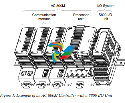
The AC 800M Controller consists of a selection of units mounted on horizontal DIN
rails, as shown in Figure 1 on page 18, which can, if required, be housed within
an enclosure.
The majority of units consist of a base mounting plate and a removable cover, which
are attached to each other by means of screws. The base plate, which is always
mounted on the DIN rail, carries the majority of the connections to the processor,
power supplies and communication interfaces, as well as to the external buses and
systems
The processor unit used for the AC 800M HI Controller is physically identical to
other AC 800M controllers, simplifying service and spares support and providing
flexibility during the project build phase. The HI functionality is extended by the
addition of a SM810/SM811 and the SIL certified software license only. This
enables non-critical control schemes to upgraded to SIL certified schemes by the
addition of a plug-in SM810/SM811, plus selection of the appropriate license.
The basic unit for a AC 800M HI consists of PM865 and SM810/SM811,
see Figure 2.
Product Benefits
Some of the benefits of the AC 800M Controller are:
• Flexibility, the AC 800M Controller can be ordered as individual units which
may be mounted in accordance with the customers own requirements.
• Extremely small footprint.
• Simple DIN rail attachment / detachment procedures, using the unique slide
& lock mechanism.
• Modularity, allowing for step-by-step expansion. You only pay for what you
require at the present time.
• Reliability and simple fault diagnosis procedures.
• Controller redundancy for higher availability (CPU, CEX-Bus, communication
interfaces, S800 I/O).
• Built-in redundant Ethernet Communication ports.
• Built-in RS-232C communication ports.
• Low power consumption, thus no external fans required.
• Flexible process connection, using either local I/O or standard fieldbuses.
• S800 I/O redundancy.
• Supports S800 I/O High Integrity (with PM865 only).
Features
The major features of the AC 800M are:
• High performance and large application memory.
• Extensive availability.
• CPU redundancy (PM861/PM864/PM865/PM866,PM891).
• AC 800M High Safety Integrity Level 2 certified using PM865/SM810/SM811.
• AC 800M High Safety Integrity Level 3 certified using PM865/SM811.
• Built-in redundant Ethernet channels.
• Built-in RS-232C channels.
• Sectioned CEX-Bus using a pair of BC810.
• Quick and simple fault-finding with the aid of LEDs on each unit / channel.
• Built-in battery back-up of memory (except for PM891).
• External battery back-up.
• Use of industry standard power supply voltage - 24V d.c.
• Easy mounting on standard DIN rail.
• IP20 Class protection without the requirement for enclosures.
• Incorporation of a wide variety of communication possibilities.
• Hardware based on standards for optimum communication connectivity
(Ethernet, PROFIBUS DP).
• Support for PROFIBUS DP fieldbus.
• Support for FOUNDATION Fieldbus.
• Support for Advant Fieldbus 100.
• Support for Modbus TCP.
• Support for Field Device Tool (FDT) and Device Type Manager (DTM)
concept for tool routing of HART instruments.
• Support for connection to INSUM via Gateway (Ethernet/LON)
• Support for IEC 61850.
• Support for PROFINET IO.
• Support for EtherNet/IP.
• Support for connection to S100 I/O.
• Support for connection to Satt I/O.
• Support for TRIO/Genius.
• Support for Genius remote I/O discrete, analog and high-speed counter blocks.
• Support for ABB Drives via PROFIBUS, ModuleBus and DriveBus.
• Support for connection to MasterBus 300.
• Full EMC certification.
• Selected units UL certified (UL508 as open equipment, and for hazardous
locations according to UL60079-15 (Class 1 Zone 2)).
Section 2 Functional Description
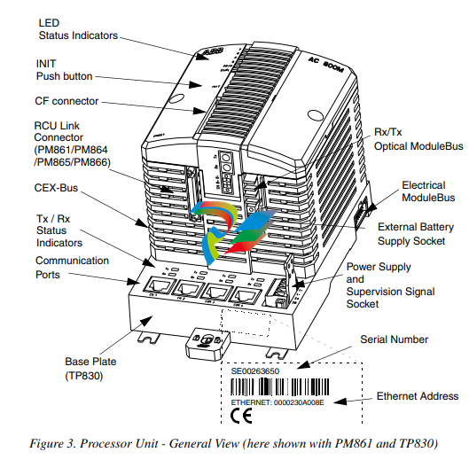
Processor Unit - General
The processor unit (except PM891) consists of two parts:
• Processor unit,
PM851/PM851A/PM856/PM856APM860/PM860A/PM861/PM861A/PM864
/PM864A/PM865/
PM866, equipped with power supply and CPU-boards
• Base plate, TP830, with a unit termination board.
The PM891 processor unit is a monolithic unit equipped with power supply and
CPU-boards, and unit termination.
The CPU board contains the microprocessor and the RAM-memory. The memory
holds an executable version of the firmware, the controller system configuration and
an application program.
The processor unit also has an optical ModuleBus used for connecting additional
clusters of S800 I/O, and a connector housing for a plug-in backup media (Secure
Digital card for PM891, and Compact Flash card for other processor units).
PM851 is equivalent to PM856 unless stated otherwise.
PM861A and PM864A are equivalent to PM861 and PM864 respectively, unless
stated otherwis
PM8xx Unit (Except PM891) The base plate of PM8xx unit (except PM891) has two RJ45 Ethernet ports (CN1, CN2) for connection to the Control Network, and two RJ45 serial ports (COM3, COM4). One of the serial ports (COM3) is an RS-232C port with modem control signals, whereas the other port (COM4) is isolated and used for the connection of a configuration tool. Both the electrical ModuleBus and the communication expansion bus (CEX-Bus) connectors are mounted on the base plate. The built-in electrical ModuleBus can be used in single CPU configuration for connecting one cluster of S800 I/O units directly to the base plate (maximum number of units per cluster is 12). However, an additional seven clusters (each comprising up to 12 units) can be added to the optical ModuleBus. The CEX-Bus is used for extending the on-board communication ports with communication interface units. It is also possible to use redundant communication interfaces on the CEX-Bus. The CEX-Bus Interconnection unit BC810 is used to increase the availability on the CEX-Bus by dividing it into separate segments. All base plates are provided with a unique Ethernet address which provides every CPU with a hardware identity. The address can be found on the Ethernet address label attached to the TP830 base plate, as shown in Figure 3 on page 25. Note that a PM851/PM851A is restricted to one Ethernet (CN1) port, thus redundant Ethernet is not available
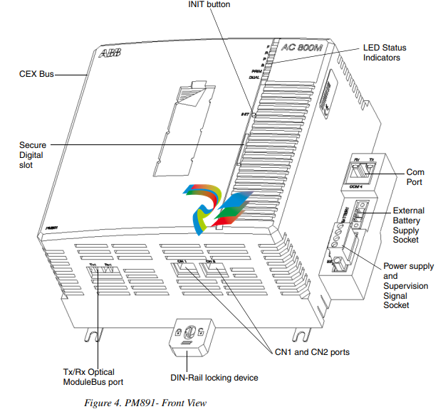
The PM891 unit has two RJ45 Ethernet ports (CN1, CN2) for connection to the Control Network, and one RJ45 serial port (COM4). The COM4 port is isolated and is used for the connection of a configuration tool. The communication expansion bus (CEX-Bus) is mounted on the unit. The CEX-Bus is used for extending the on-board communication ports with communication interface units. It is also possible to use redundant communication interfaces on the CEX-Bus. The CEX-Bus Interconnection unit BC810 is used to increase the availability on the CEX-Bus by dividing it into separate segments. The optical Modulebus at the bottom of the unit can be used for connecting seven clusters of S800 I/O units (each comprising up to 12 units). Each PM891 unit is provided with a unique Ethernet address which provides hardware identity to the unit. The address can be found on the Ethernet address label located on the right-hand side of the unit.
Following a changeover, the system operates as a system without redundancy with
only one processor unit in operation. You can replace the malfunctioning processor
unit while the system is running. After the replacement is carried out, the system
once again has a redundant processor unit.
If an error arises in the backup unit, you can also replace the backup unit while the
system is running.
Errors which occur in the backup unit can never affect the primary unit's operation.
The primary unit and the backup unit are logically separated from one another.
Hardware errors in the primary processor unit cause the system to perform a correct
changeover. These hardware errors are "single errors".
The application programming and the communication are totally unaffected by the
redundancy.
The serial port COM3, can not be used in redundant CPU configuration.
S800 I/O units are connected to the two CPUs by the optical ModuleBus. The
built-in electrical ModuleBus on the base plates can not be used for connection of
S800 I/O in redundant CPU configuration.
Communication
The number of ports and protocols, provided by the processor unit, can be expanded
by adding communication units to the CEX-Bus.
Examples of unit types that may be connected to the CEX-Bus are as follows:
• FOUNDATION Fieldbus High Speed Ethernet (FF HSE)
• PROFIBUS DP
• Dual RS-232C ports
• S100 I/O
• INSUM
• IEC 61850
• MasterBus 300
• Modbus TCP
• ABB Drives via DriveBus Interface
• TRIO/Genius
• Satt I/O via ControlNet (19” Satt rack I/O, S200 I/O and S200L I/O)
• AF 100
• PROFINET IO
• EtherNet/IP
This expansion provides the means of connecting remote I/O, fieldbus instruments
and additional RS-232C ports.
Battery Back-up
A battery is used to power the back-up for both the RAM and the real time clock in
the case of a power failure. Battery back-up can be provided in two ways:
• using the internal battery (as shown in Figure 6 on page 33). The internal
battery is not available in PM891.
• using an external battery unit, (SB821), for longer back-up times.
• using an external rechargeable battery unit, (SB822), for longer back-up times.
The external battery unit is mounted on the DIN rail and connected to the CPU via a
cable.
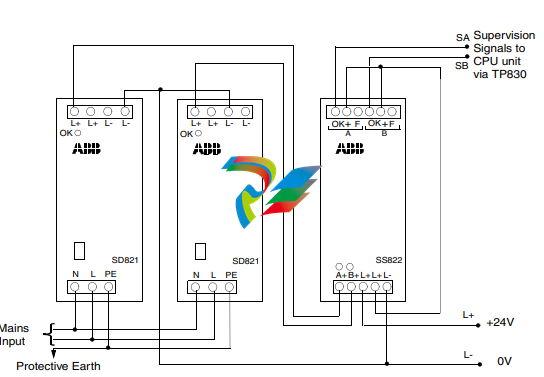
Power Supply
The power supply units (SD83x) are switch-mode power converters that convert a.c.
mains supply voltage to a regulated 24 V d.c. The mains input supply voltage can
either be 115 V a.c. or 230 V a.c. and is selected using a switch, mounted on the
front panel of the unit.
The power supply units can be used in both redundant and non-redundant
applications. When redundant power supply units are connected to a common load,
a voting device, (SS823), must be used to combine the two outputs to a single
output, via diodes. The redundant power supply units may be connected to
completely separate mains supplies or to the same mains supply, depending on the
configuration selected.
The L- output (0 V) of the power supply units can be used without being grounded.
If grounding is required, the power supply unit L- output (0 V) can be grounded
directly or via a suitable resistor.
The processor unit has no requirement for an uninterruptible power supply in order
to shut down safely. The processor unit has an internal power reservoir that lasts for
5 ms, which is sufficient for it to make a controlled power down. The power supply
units easily handle short power interruptions (<20 ms) that can normally occur
within any industrial environment. Despite this, it is sometimes necessary to protect
certain applications, from brief voltage failures, by installing Uninterruptible Power
Supply (UPS) devices.
For information on SD83x, refer to Power Supply Units - SD831, SD832, SD833,
and SD834 on page 102.
Powering from an External Source
The AC 800M Controller can be powered from an external +24 V DC source. This
source is often common for many different types of plant equipment, resulting in
long power cables to the AC 800M Controller. Furthermore, heavy load changes can
cause variations in controller supply voltage making it necessary to take precautions
against low voltage in order to prevent controller malfunction.
Should there be a risk that the +24 V at the PM8xx power terminals could drop
below 19.2 V for more than 1 ms, then an energy reservoir must be used for
Powering Units.
ABB strongly recommends using a DC/DC converter and extra energy reservoir in
case external DC-supply with longer cables than 10 m is used.
I/O System
There are several methods of connecting I/O systems to the AC 800M Controller:
• S100 I/O via CI856.
• S800 I/O units via the ModuleBus. Support for hot configuration during run,
redundancy on all levels, HART routing, and Sequence-of-Events (SOE).
• S800 I/O units via CI854/CI854A and CI840, PROFIBUS DP. Support for
HART routing, redundancy on all levels, and hot configuration during run.
• S800 I/O units via CI854/CI854A and CI801, PROFIBUS DP. Support for
HART routing, and hot configuration during run.
• S900 I/O units via CI854/CI854A, PROFIBUS DP.
• ABB Drives can be connected to the ModuleBus, via CI801. Some Drives
equipment can be connected directly to PROFIBUS or PROFINET IO. Please
refer to Drives-specific documentation for more information.
• Genius remote I/O (TRIO) via the CI862.
• Satt I/O on ControlNet (19” Satt rack I/O, S200 I/O and S200L I/O) via the
CI865.
• PROFINET IO via CI871
For further information about supported I/O-units, refer to I/O-specific
documentation, see Released User Manuals and Release Notes on page 16.
S800 I/O
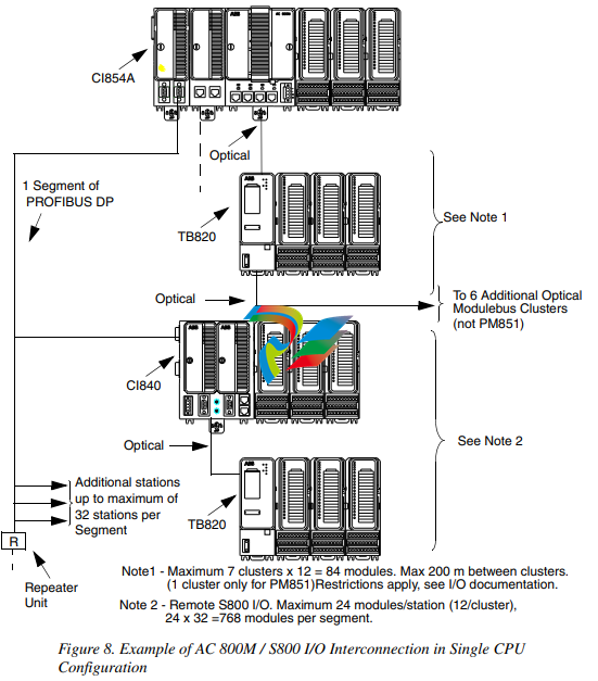
See Figure 8 on page 40 for examples of AC 800M / S800 I/O interconnection.
The top right area of Figure 8 on page 40 shows one cluster (or group) of units,
connected to the built-in electrical ModuleBus of an AC 800M Controller. The
maximum number of units per cluster is 12. However, a further seven clusters, each
comprising of up to 12 units, can be added to the optical ModuleBus. This results in
a total count of 96 units for the local ModuleBus.
S100 I/O
S100 I/O are connected to the AC 800M, via the communication unit CI856. A bus
extension cable TK575/TK580, together with DSBC174/DSBC176 or DSBC173A,
connects the S100 I/O units to the base plate, TP856, of CI856. Up to five S100 I/O
racks can be connected to the CI856.
Redundant S100 I/O bus extension can not be connected to CI856.
S900 I/O
S900 I/O are connected to the AC 800M, via PROFIBUS DP and CI854/CI854A.
The S900 I/O system is a remote I/O system for use in hazardous areas. Due to its
explosion protection certificates, the S900 process I/O system can be installed in
both hazardous areas (zone 1 and zone 2) and safe areas.
Other I/O Systems
A PROFIBUS DP segment (or node), shown on the top left-hand side of Figure 8 on
page 40, allows for a large increase in the numbers of units connected to each
AC 800M Controller. The segment is shown here with a Fieldbus Communications
Interface (FCI) unit (type CI840), connected to the PROFIBUS DP network. The
use of FCI units, or other types of adapters, allows the selection of units from
several I/O families.
In redundant CPU configuration, connection of S800 I/O is done only with the
optical ModuleBus. See Figure 9 on page 41. Each cluster of I/O units is
connected to two TB840s. Each processor unit is connected to one of the
TB840s. Note that the built-in electrical ModuleBus can not be used in redundant
CPU configuration.
Note that a PM851/PM851A is restricted to one optical ModuleBus cluster.
Genius remote I/O (TRIO)
TRIO is a remote I/O product that provides discrete, analog and high-speed counter
blocks for connection to the AC 800M. Configuration of the I/O block units and the
CI862 is done using Control Builder M.
The CI862 Communication Expansion Module (CEM), connects a TRIO Field Bus
to the controller AC 800M. The connection between CI862 and AC 800M is done
via the CEX-Bus.
A single CI862 can connect 30 blocks to a single LAN. The AC 800M can have up
to four single lans or four redundant lans. The maximum I/O with TRIO in an
AC 800M is 1000 IO points.The CI862 can be set redundant.
TRIO blocks, are self-contained, configurable I/O blocks used to interface field
devices to the CI862 communications bus. These blocks can be individually
installed on machines, in junction boxes, or grouped in racks or panels. A TRIO
block is made of cast aluminum, and weighs approximately 1.8 kg (4 pounds). It
measures approximately 22.5 x 10 x 7.5 cm (9 x 4 x 3 inches). Each block has its
own communications capability and microprocessor, and provides from 6 to 32
circuits for connecting input and output devices. You can place blocks on the bus in
any combination or sequence. You can use a mix of blocks on the same bus.
Satt I/O interface
The Satt I/O system consists of Rack I/O and Series 200 I/O family (S200 I/O,
S200L I/O and I/O 200C). CI865 connects to Rack I/O, via the adapter 200-RACN,
and to Series 200 I/O family, via the adapter 200-ACN.
The CI865 module is the AC 800M system’s communication interface for
Satt ControlNet and bridges different bus standards used on AC 800M and
Satt ControlNet. The CI865 module makes it possible to use older Satt I/O system
(Rack I/O and Series 200 I/O) with the AC 800M controller platform but it can not
be used as a general ControlNet interface. CI865 supports online replacement (Hot
Swap), and does not require any configuration before installation.
CI862 cannot be used in an AC 800M High Integrity controller
CI865 cannot be used in an AC 800M High Integrity controller.
FOUNDATION Fieldbus High Speed Ethernet (FF HSE)
The FF HSE communication interface unit CI860 makes it possible for AC 800M
controllers to communicate with FF HSE devices via Ethernet. The FOUNDATION
Fieldbus Linking Device LD 800HSE (see Appendix B, Recommended
Components) makes it possible for AC 800M controllers to communicate with
FOUNDATION Fieldbus H1 devices, via CI860 and Ethernet. An example system
structure with a single CPU is given in Figure 10 on page 42. An example system
structure with a redundant CPU is given in Figure 11 on page 43.
CI860 cannot be used in an AC 800M High Integrity controller.
The following schematic figures, with examples of I/O interconnections, do not
necessarily show the exact amount of connectors or their exact positions.
Drive System
ABB Standard (Std) and Engineered (Eng) Drives can be connected to AC 800M
through any of the following:
• The optical ModuleBus
• CI801 and PROFIBUS DP
• NPBA-12, RPBA-01, or FPBA-01 PROFIBUS DP Adaptor modules along
with CI854
• RETA-02 or FENA-01/-11 Ethernet Adapter modules along with CI871
(PROFINET IO)
• CI858 DriveBus Interface. .
ModuleBus
In single CPU configuration, ABB Drives can be connected to the processor unit via
the optical ModuleBus. See Figure 12 on page 47. The number of ABB Drives
which can be connected to the optical ModuleBus, can be described by the
following equation:
(No. of ABB Drives) < 84 - (12 x (No. of TB820s))
that is, each Drive uses one ModuleBus cluster.
PROFIBUS
In single and redundant CPU configuration, ABB Drives can be connected via
PROFIBUS DP and CI801. See Figure 12 on page 47. Only Standard Drives can be
connected to CI801. Fourteen (14) Standard Drives can be connected to each CI801
if there are no I/O units connected. For the number of Drives that can be connected
to the same CI801, when both I/O units (TB820) and Standard Drives are
connected, refer to documentation about FCI for PROFIBUS DP.
For more information about ABB Drives and its types (Std and Eng) refer to
S800 I/O documentation.
For information about Branching Unit (See Figure 12 on page 47) see ABB Drive
System documentation.
CI858 cannot be used in an AC 800M High Integrity controller.
ABB drives can also be connected via PROFIBUS DP (CI854/CI854A), with direct
connection to PROFIBUS DP slave modules NPBA-12, RPBA-01, and FPBA-01.
PROFINET IO and CI871
The RETA-02 Ethernet Adapter module and FENA-01/-11 Ethernet Adapter
module are optional devices for ABB drives, which enables the connection of the
drive to a PROFINET IO (PNIO) network. The drive is considered as a PNIO device
on the PROFINET IO network, and it is compatible with all PNIO controller
stations that support PROFINET IO and sub-slots.
DriveBus Interface
ABB drives can be connected to the AC 800M via the CI858 unit, see Figure 12 on
page 47 and Figure 13 on page 48. The drive interface can be used for controlling up
to 24 drives or inverter units.
Main communication functions of the drive connection are:
• dataset communication
• broadcast system time
• supervision and diagnostics functions
The data exchange between the AC 800M and the CI858 consists of eight datasets.
The drive connection is able to transfer at the maximum 8 datasets / 1 ms.
Connection of multiple drives requires the use of a branching unit, which enables
the construction of a logical bus with physical star topology, see Figure 13 on page
48. The branching units can be chained.
The following drives are supported by the drive connection:
• ACS 600 single drive
• ACS 600 multi drive
• ACS 600 thyristor supply units
• ACS 600 IGBT supply units
• ACS 800 product family
• ACS 140-AC S400
• DCS 600 and DCS 400
• ACS 6000 product family / large drives
• ACS 1000 product family
For more information about ABB Drives and its types (Std and Eng) refer to
S800 I/O documentation, see Released User Manuals and Release Notes on page
16.
For information about Branching Unit (Figure 13 on page 48) see ABB Drive
System documentation.
The following schematic figures, with examples of I/O interconnections, do not
show the placement of the connectors.
Installation
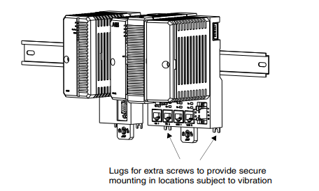
The AC 800M Controller consists of units that are mounted on a horizontal DIN rail
as shown in Figure 16 on page 51. Each base plate has a locking device that ensures
contact between the metal back plate and the DIN rail, providing an effective ground
connection.The locking device can be set to any of the following three positions,
OPEN, SLIDE or LOCKED, which makes installation and removal of the base
plates very simple.
There are two ways of mounting the products concerned in cabinets, open rack or
other types of installations; aluminum profile with mounted DIN-rail, see Figure 14,
or DIN-rail mounted on a metal sheet of proper size, see Figure 15.
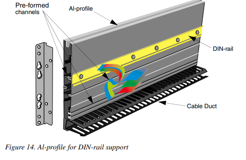
The aluminum profile or metal sheet shall be properly connected to protective earth.
DIN-rail type with height 7.5 mm shall be used. Refer to type NS 35/7.5 according
to standard EN 50022.
Figure 15. Mounted on Metal Sheet
It is not allowed to manipulate CEX bus base plates in a powered and running
system. Before changing or removing a base plate, all CEX modules on that
segment must be remove
The AC 800M and S800 I/O-units have protection class IP 20. If a higher IP class is
required, an additional enclosure is needed
Configuration
Using the Control Builder interface, it is possible to download controller firmware
and configure hardware (I/O and communication units). It is also possible to make
application programs with IEC61131-3 and compile and run programs off-line, as
an aid to process simulation, before finally downloading an application to the
controller.
The Control Builder interface is part of the Industrial IT 800xA System, which runs
on a PC and is normally connected to the AC 800M controller via the Control
Network, using the CN1 or CN2 port on the AC 800M controller. Alternatively, the
PC could be connected to the controller via the controller COM4 port (RS-232C). In
that case, use the tool cable TK212 and a serial port on the PC.
Note that a PM851/PM851A is restricted to one Ethernet (CN1) port, thus
redundant Ethernet is not available.
Note that Control Builder as standard does not support CI862. If CI862 is to be
used, suitable system extension must be installed.
-
 Hirschmann RS20-1600M2T1SDAEHH03.1.02 Rail Switch
 -
 Hirschmann BRS30-24TX Industrial Rail Switch
 -
 Hirschmann RSPM20-4T14T1EV9HHS999.9.99 Managed Ethernet Switch
 -
 Hirschmann BELDEN RS40-0009CCCCSDAPHH09.0.14 / RS400009CCCCSDAPHH09014
 -
Hirschmann RS40 Rail Switch RS40-0009CCCCSDAE
-
 Hirschmann BELDEN RS30-0802T1T1SDAP / RS300802T1T1SDAP Fully Managed Layer 2 Compact Rail Switch
 -
 Hirschmann BELDEN RS20-0800M2M2SDAUHH / RS200800M2M2SDAUHH
 -
 Hirschmann EAGLE30-04022O6TT999SCCY9HSE3F Industrial Firewall Router Switch
 -
 Hirschmann RS20-1600T1T1SDAEHH09.0.14 RS20 Rail Mount Ethernet Switch
 -
 Hirschmann EAGLE0200T1T1TDDY90000HHE05.3.03 Industrial Security Router
 -
Hirschmann - BELDEN MIPP-AD-1L9P
-
 HIRSCHMANN RSPM20-4Z64Z6TV9HHS9 942 106-999 RAIL SAFETY SWITCH
 -
 HIRSCHMANN FIBEROPTIC MODULE FIP P/N: OZDFIPG3T
 -
 HIRSCHMANN RS20-1600M2M2SDAUHH Ethernet rack-mounted switch
 -
 HIRSCHMANN BELDEN RS20-0400T1T1SDAEHH04.0.01 / RS200400T1T1SDAEHH04001
 -
HIRSCHMANN MM2-4FXM3 MICE Media Module
-
HIRSCHMANN RS20-0800M2M2SDAE Industrial Ethernet Rail Switch
-
 Hirschmann RS20-2400T1T1SDAP / RS20-2400T1T1SDAPHH05.0.02
 -
 GE MLJ1005B010H00C MLJ Digital Synchromism Check
 -
 ALSTOM MICROTECH DX21-M2 Digital Excitation Controller
 -
HIRSCHMANN BRS20-1200ZZZZ-STCY99HHSES
-
 HIRSCHMANN MM3-4FXM2 MICE Media Module
 -
Hirschmann RSB20-0800T1T1SAABHH 8Port ENet Rail Switch RSB20
-
 Hirschmann MACH102-8TP Ethernet Switch
 -
 SAACKE DDZ-M marine steam pressure atomizer
 -
 SAACKE SKV-A marine rotary cup atomizer
 -
 SAACKE Seavis HMI05e
 -
 Kollmorgen MMC-SD-2.0-230 Servo Drive 100-240VAC 2KW 10A Output 3PH 100-240VAC
 -
 Kollmorgen Servo drive CR10550
 -
 Kollmorgen AKD-P01207-NACN-0054 Servo Driver
 -
 Kollmorgen S406M-CA-036 Servostar
 -
.png) Kollmorgen AKD-B02407-NAAN-0000 Digital Servo Drive
Kollmorgen AKD-B02407-NAAN-0000 Digital Servo Drive -
 Kollmorgen SERVOSTAR S406AM-CA Digital Servo Drive
 -
 KOLLMORGEN SERVOSTAR 603-AS SERVO AMPLIFIER_SERVOSTAR603AS_S60301
 -
Kollmorgen S700 Servo Controller (S70602-NANANA-NA)
-
 Kollmorgen MPK411 controller
 -
 KOLLMORGEN MMC-SD-1.3-460-D Smart Drive
 -
 KOLLMORGEN AKM21C-CKB2AA-00 / AKM21CCKB2AA00 Servomotor
 -
 BECKHOFF AX5106-0000-0200 | Digital Compact Servo Drives 1-channel
 -
 BECKHOFF C3620-0000 INDUSTRIAL COMPUTER (MOTORSHELVES)
 -
 Beckhoff EK1960-0000 TwinSAFE Compact Controller
 -
 Beckhoff C6930-0050 Control Cabinet Industrial PC
 -
 Beckhoff CP7711-0001-0030 Industrial Computer Detection
 -
 Beckhoff CX1001-0111 Embedded PC CPU Module
 -
 Beckhoff C6017-0020 | Ultra-compact Industrial PC
 -
 Beckhoff EK1322 | 2-port EtherCAT P junction with feed-in
 -
 Beckhoff CP2219-0010 Panel
 -
 BECKHOFF C6015-0020 ULTRA COMPACT INDUSTRIAL PC
 -
 BECKHOFF CX2030-0120/Standard CPU Module Embedded PC Windows PLC controller
 -
 Beckhoff CP7721-1090-0020 Panel PC
 -
 Beckhoff PC CPU Module CX5130-0175
 -
 Beckhoff C6920-0050 Control Cabinet
 -
 Beckhoff EL6631 EtherCAT 2-Port Communication Interface, Profinet RT Controller
 -
 Beckhoff CP6202-0001-0060 touch screen panel PC
 -
 Beckhoff CP3916-1002-0000 Multi-Touch Control Panel
 -
 Beckhoff EP1809-0021 | EtherCAT Box, 16-channel digital input, 24 V DC, 3 ms, M8Preferred type
 -
 Beckhoff CX8190 PLC Embedded Industrial PC Ethernet Controller
 -
 Beckhoff CX2100-0914 Power Supply for External
 -
 Beckhoff Automation CP6906-0001-0000 HMI
 -
 Beckhoff EP7342-0002 Module
 -
 Beckhoff CX1020-0112 / CX1100-0910 / CX1020-N010 / CX1100-0003 Windows CPU
 -
 Beckhoff EP7211-0034 EtherCAT Box 1 Channel Motion Interface
 -
 Beckhoff C6240-0030 Control cabinet Industrial PC
 -
 beckhoff motherboard CB1052-0004 CB1052-0004
 -
 Beckhoff AX2006-AS Servo Drive / Variable Frequency Drive
 -
BECKHOFF CP6207-0001-0020 NSMP
-
 Beckhoff C6930-1142-0060 Industrial Computer
 -
 Beckhoff FC7501-0000 interface card
 -
 Beckhoff CX5140-0175 Embedded PC PLC CPU CX5140 Industrial Controller
 -
 Beckhoff CP7802-1100-0010: High-End IP65 Control Panel with DVI/USB Extended Interface
 -
BECKHOFF CP3716-1058-0010 CONTROL PANEL
-
 Beckhoff AX8108-0000 Single-Axis Module
 -
 Beckhoff CU8851-0000 | USB extension, USB Extended 2.0 receiver box
 -
Beckhoff C6017-0030 | Ultra-compact Industrial PC
-
 Beckhoff CX1001-0120/CX10010120.cx1000-n001.cx1000-n000 System Overview
 -
 Beckhoff CPU Module CX5140-0155/4GB CPU Module
 -
 Beckhoff CP6533-0001-005: Built-in Panel PC with High-Definition Multi-Touch Control
 -
 Beckhoff EL5042 | EtherCAT Terminal, 2-channel encoder interface, BiSS® C
 -
 Beckhoff C6920-1080-0040: Premium Control Cabinet Industrial PC
 -
 Beckhoff C6920-0060 | Control cabinet Industrial PC
 -
 Beckhoff Embedded-PC CX5010-1121
 -
 Beckhoff CB3050-0010 Mainboard Motherboard
 -
 Beckhoff PLC module CX1020-0000 Basic CPU module (service phase)
 -
 Beckhoff CP7812-1056-0010 15" Multitouch Display Control Panel
 -
 Beckhoff CX5120-0115 /2GB Controller Module
 -
 Beckhoff CP7201-1000-0000 Industrial Panel PC
 -
 Beckhoff Servo Motor AM8061-0JH1-0000
 -
 BECKHOFF CP6503-0001-0050 Built-in Panel PC
 -
Beckhoff CP3919-0010 Display G190ETN01.2 19" PCT V04. Multi-touch Control Panel
-
 Beckhoff CX5110-0112-9020/000368201 Embedded PC Intel Atom Processor
 -
 Beckhoff AX8206-0000 Dual-Axis Module
 -
Beckhoff Nail Operating Terminal CP7032-1031-0010
-
Beckhoff AM8042-0EH1-0000 Servomotor 4.10 Nm (M0), F4 (87 mm)
-
 Beckhoff EK9300 Beckhoff CPU Module
 -
Beckhoff CP3224-0020 Multitouch-Panel-PC
-
 Beckhoff CP2712-0000 12.1" 24VDC Touch Screen WMD0
 -
 BECKHOFF CX5240-0195 / 0000289234 Embedded PC 40 GB CFast Card
 -
 Beckhoff CP6932-1000-0000 Control Panel
 -
 BECKHOFF CX5120-0121 PLC Module
 -
 Beckhoff EL3218 | EtherCAT Terminal, 8-channel analog input
 -
Beckhoff C6640-0050 | Control cabinet Industrial PC
-
 Beckhoff Cx5130-0120/4GB Embedded-PC
 -
 BECKHOFF CX2030-0122 PLC PROCESSOR
 -
 BECKHOFF CX5020-0122 Controller Module
 -
 Beckhoff CP3915-0000 Multitouch Panel
 -
 BECKHOFF EL3014 | EtherCAT Terminal
 -
 BECKHOFF Industrial Computer c6920-1057-0030
 -
 Beckhoff CX5130-0141/4GB CX5130-0141 Embedded PC
 -
 Beckhoff C6240-1052-0040 4-086-06-3073 Industrial Computer
 -
 Beckhoff CX5140-0135 /4GB High-Performance Embedded Industrial PC
 -
 Beckhoff C6515-1001-0000 Industrial PC
 -
 Beckhoff AX5103-0000-0200 - Digital Compact Servo Drives
 -
 Beckhoff CX2030-0130-1003/4GB Basic CPU module
 -
 Beckhoff AX8620-0000 Power Supply Module
 -
 Beckhoff CX9020-0111 module with
 -
 Beckhoff EL7332 PLC Module
 -
 BECKHOFF CP7709-0001-0020 HMI
 -
 Beckhoff CX5120-0155/2GB Embedded PC
 -
 BECKHOFF CP7037-1037-0010 OPERATOR INTERFACE TOUCHSCREEN
 -
 Beckhoff EK9000 | ModbusTCP/UDP Bus Coupler
 -
 Beckhoff Touch Panel Screen CP6020 -0000-0000
 -
 Beckhoff CX2020-0121 Module FAST Shipping
 -
 Beckhoff CX2030-0125 Basic CPU Module
 -
 Beckhoff CP3918-0000 Multi-Touch 18.5" Control Panel
 -
 Automotion LC4A00010 DC BL Motor Control, ATS, Sub Assy, SCP, 115VAC,
 -
 500T-115VAC - VAS ENGINEERING - DORIC 500 SERIES DIGITAL TEMP INDICATOR
 -
 Honeywell X-DCS2000/EN Digital Integrated System Manager 50/60Hz 100-240V #4
 -
 Kollmorgen S60600 Servostar600 606-Fan 4 kVA, 6 A, 3 X 230 - 480 V


