
ABBDistributed busbar protection REB500 including line and transformer protection Product Guide
Distributed busbar protection REB500
including line and transformer protection
Main features • Low-impedance busbar protection
• Stub and T-zone protection
• High functional reliability due to two independent measurement criteria:
- stabilized differential current algorithm
- directional current comparison algorithm
• Phase-by-phase measurement
• Reduced CT performance requirements
• High through-fault stability even in case of
CT saturation
• Full solid-state busbar replica
• No switching of CT circuits
• Only one hardware version for
- 1 and 5 A rated currents
- all auxiliary supply voltages between
48 V DC and 250 V DC
- nominal frequencies of 50, 60 and
16.7 Hz
• Short tripping times independent of the
plant’s size or configuration
• Centralized layout: Installation of hardware
in one or several cubicles
• Distributed layout: Bay units distributed
and, in the case of location close to the
feeders, with short connections to CTs, isolators, circuit breakers, etc.
• Connections between bay units and central
unit by fiber-optic cables
- maximum permissible length 1200 m
- for distributed and centralized layout
• fiber-optic connections mean interferenceproof data transfer even close to HV power
cables
• Replacement of existing busbar protection
schemes can be accomplished without restrictions (centralized layout) in the case of
substation extensions e.g. by a mixture of
centralized and distributed layout
• Easily extensible
• User-friendly, PC-based human machine
interface (HMI)
• Fully numerical signal processing
• Comprehensive self-supervision
• Binary logic and timer in the bay unit
• Integrated event recording
• Integrated disturbance recording for power
system currents
• A minimum of spare parts needed due to
standardization and a low number of varying units
• Communication facilities for substation
monitoring and control systems via
IEC 61850-8-1, IEC 60870-5-103 and LON
• IEC 62439 standard redundant station bus
communication
• IEC 61850-9-2 LE process bus communication
• Cyber security to support
- User Access Management
- User Activity Logging
Options
• Breaker failure protection (also separately
operable without busbar protection)
• End fault protection
• Definite time overcurrent protection
• Breaker pole discrepancy
• Current and voltage release criteria
• Disturbance recording for power system
voltages
• Separate I0 measurement for impedancegrounded networks
• Communication with substation monitoring
and control system (IEC 61850-8-1 /
IEC 60870-5-103 / LON)
• Internal user-friendly human machine interface with display
• Redundant power supply for central units
and/or bay units
Additional
main features
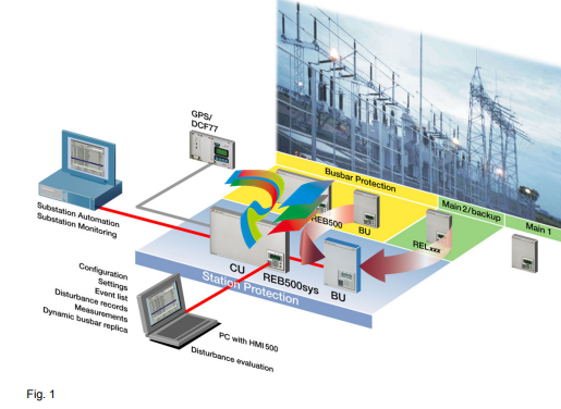
REB500sys combines the well-proven numerical busbar and breaker failure protection
REB500 of ABB with Main 2 or back-up protection for line or transformer feeders. The
Main 2 / Group 1 or back-up protection is
based on the well-proven protection function
library of ABB line and transformer protection
for 50, 60 and 16.7 Hz.
Main 2 / back-up bay protection
• Definite and inverse time over- and undercurrent protection
• Directional overcurrent definite and inverse
time protection
• Inverse time earth fault overcurrent protection
• Definite time over- and undervoltage protection
Distributed busbar protection REB500
including line and transformer protection
Page 3
• Three-phase current and three-phase voltage plausibility
Main 2 / back-up bay protection:
Line protection
• High-speed distance protection
• Directional sensitive earth fault protection
for grounded systems against high resistive faults in solidly grounded networks
• Directional sensitive earth fault protection
for ungrounded or compensated systems
• Autoreclosure for
- single-pole / three-pole reclosure
- up to four reclosure sequences
• Synchrocheck with
- measurement of amplitudes, phase
angles and frequency of two voltage
vectors
- checks for dead line, dead bus, dead
line and bus
Group 1 / back-up bay protection:
Transformer protection
• High-speed transformer differential protection for 2- and 3-winding and auto-transformers
• Thermal overload
• Peak value over- and undercurrent protection
• Peak value over- and undervoltage protection
• Overfluxing protection
• Rate of change frequency protection
• Frequency protection
• Independent T-Zone protection with transformer differential protection
• Power protection
Application REB500
The numerical busbar protection REB500 is
designed for the high-speed, selective protection of MV, HV and EHV busbar installations
at a nominal frequency of 50, 60 and 16.7 Hz.
The structure of both hardware and software
is modular enabling the protection to be easily
configured to suit the layout of the primary
system.
The flexibility of the system enables all configurations of busbars from single busbars to
quadruple busbars with transfer buses, ring
busbars and 1½ breaker schemes to be protected.
In 1½ breaker schemes the busbars and the
entire diameters, including Stub/T-Zone can
be protected. An integrated tripping scheme
allows to save external logics as well as wiring.
The capacity is sufficient for up to 60 feeders
(bay units) and a total of 32 busbar zones.
The numerical busbar protection REB500
detects all phase and earth faults in solidly
grounded and resistive-grounded power systems and phase faults in ungrounded systems
and systems with Petersen coils.
The main CTs supplying the currents to the
busbar protection have to fulfil only modest
performance requirements (see page 18). The
protection operates discriminatively for all
faults inside the zone of protection and
remains reliably stable for all faults outside the
zone of protection.
REB500sys
The REB500sys is foreseen in MV, HV and
EHV substations with nominal frequencies of
16.7, 50 Hz or 60 Hz to protect the busbars
and their feeders. The bay protection functions included in REB500sys are used as
Main 2 / Group 1 - or back-up protection.
The system REB500sys is foreseen for all single or double busbar configurations (Line variants L-V1 to L-V7 and Transformer variant TV1 to T-V4). In 1½ breaker configurations,
variant L-V5 can be used for the bay level
functions autoreclosure and synchrocheck.
The capacity is sufficient for up to 60 feeders
(bay units) and a total of 32 busbar zones.
The REB500sys detects all bus faults in solidly and low resistive-grounded power systems, all kind of phase faults in ungrounded
and compensated power systems as well as
feeder faults in solidly, low resistive-grounded,
compensated and ungrounded power systems.
The protection operates selectively for all
faults inside the zone of protection and
remains reliably stable for all faults outside the
zone of protection.
REB500sys is perfectly suited for retrofit concepts and stepwise upgrades. The bay unit is
used as a stand-alone unit for bay protection
functions (e.g. line protection, autoreclosure
and synchrocheck or 2- and 3 winding transformer protection or autonomous T-zone protection). The central unit can be added at a
later stage for full busbar and breaker failure
protection functionality.
Distributed busbar protection REB500
including line and transformer protection
Depending on the network voltage level and
the protection philosophy the following protection concepts are generally applied:
• Two main protection schemes per bay
and one busbar protection.
With REB500sys the protection concept
can be simplified. Due to the higher integration of functionality one of the main protection equipment can be eliminated.
• One main protection and one back-up
protection scheme per bay, no busbar
protection.
With REB500sys a higher availability of the
energy delivery can be reached, due to the
implementation of busbar and breaker failure protection schemes where it hasn't
been possible in the past because of economical reasons.
Nine standard options are defined for Main 2/
Group 1 or back-up bay level functions:
Line protection
- Line variant 1 (L-V1)
directional, non-directional overcurrent and
directional earth fault protection
- Line variant 2 (L-V2)
as line variant L-V1 plus distance prot.
- Line variant 3 (L-V3)
as line variant L-V2 plus autoreclosure
- Line variant 4 (L-V4)
as line variant L-V3 plus synchrocheck
- Line variant 5 (L-V5)
as line variant L-V1 plus autoreclosure and
synchrocheck.
- Line variant 6 (L-V6) for 16.7 Hz
non-directional overcurrent, distance protection, autoreclosure.
- Line variant 7 (L-V7) for 16.7 Hz
as line variant L-V6 plus directional earth
fault protection for grounded systems
Transformer protection
- Transformer variant 1 (T-V1)
2- or 3 winding transformer differential protection, thermal overload, current functions;
applicable also as autonomous T-zone protection.
- Transformer variant 2 (T-V2)
2-winding transformer differential protection, thermal overload, current functions,
overfluxing protection, neutral overcurrent
(EF).
- Transformer variant 3 (T-V3)
Distance protection for transformer back-up
or 2-winding transformer differential protection, thermal overload, current functions,
voltage functions, frequency functions,
power function, overfluxing protection.
- Transformer variant 4 (T-V4)
Transformer oriented functions/ back-up
functions -> thermal overload, current functions, voltage functions, frequency functions, power function, overfluxing protection.
Distributed busbar protection REB500
including line and transformer protection
Mode of
installation
There are three versions of installing the numerical busbar protection REB500 and the numerical station protection REB500sys:
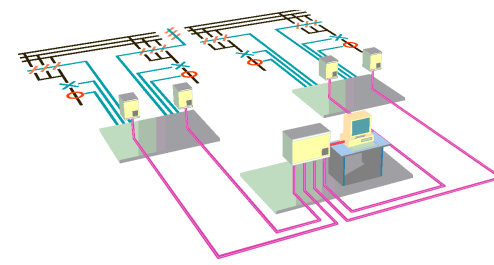
Distributed installation
In this case, the bay units (see Fig. 24) are
installed in casings or cubicles in the individual switchgear bays distributed around the
station and are connected to the central processing unit by optical fiber cables. The central processing unit is normally in a centrally
located cubicle or in the central relay room.

Centralized installation
19" mounting plates with up to three bay units
each, and the central processing unit are
mounted according to the size of the busbar
system in one or more cubicles (see Fig. 23).
A centralized installation is the ideal solution
for upgrading existing stations, since very
little additional wiring is required and compared with older kinds of busbar protection,
much more functionality can be packed into
the same space.
Combined centralized and distributed
installation
Basically, the only difference between a distributed and a centralized scheme is the
mounting location of the bay units and therefore it is possible to mix the two philosophies
Distributed busbar protection REB500
including line and transformer protection
Page 7
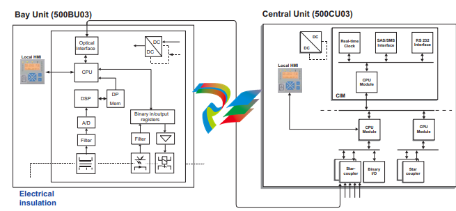
System design Bay unit (500BU03)
The bay unit (see Fig. 4) is the interface
between the protection and the primary system process comprising the main CTs, isolators and circuit-breaker and performs the
associated data acquisition, pre-processing,
control functions and bay level protection
functions. It also provides the electrical insulation between the primary system and the
internal electronics of the protection.
The input transformer module contains four
input CTs for measuring phase and neutral
currents with terminals for 1 A and 5 A. Additional interposing CTs are not required,
because any differences between the CT
ratios are compensated by appropriately configuring the software of the respective bay
units.
Optional input transformer module also contains five input voltage transformers for the
measurement of the three-phase voltages and
two busbar voltages and recording of voltage
disturbances or 6 current transformers for
transformer differential protection. (see
Fig. 12).
In the analog input and processing module,
the analog current and voltage signals are
converted to numerical signals at a sampling
rate of 48 samples per period and then
numerically preprocessed and filtered accordingly. Zero-sequence voltage and zero-current
signals are also calculated internally. The Process data are transferred at regular intervals
from the bay units to the central processing
unit via the process bus.
Every bay unit has 20 binary inputs and 16
relay outputs. The binary I/O module detects
and processes the positions of isolators and
couplers, blocking signals, starting signals,
external resetting signals, etc. The binary
input channels operate according to a patented pulse modulation principle in a nominal
range of 48 to 250 V DC. The PC-based HMI
program provides settings for the threshold
voltage of the binary inputs. All the binary output channels are equipped with fast operating
relays and can be used for either signaling or
tripping purposes (see contact data in Table
8).
A software logic enables the input and output
channels to be assigned to the various functions. A time stamp is attached to all the data
such as currents, voltages, binary inputs,
events and diagnostic information acquired by
a bay unit.
Where more binary and analog inputs are
needed, several bay units can be combined to
form a feeder/bus coupler bay (e.g. a bus coupler bay with CTs on both sides of the bus-tie
breaker requires two bay units).
The bay unit is provided with local intelligence
and performs local protection (e.g. breaker
failure, end fault, breaker pole discrepancy),
bay protection (Main 2 or back-up bay protections) as well as the event and disturbance
recording.
Distributed busbar protection REB500
including line and transformer protection
In the event that the central unit is out of operation or the optical fiber communication is disrupted an alarm is generated, the bay unit will
continue to operate, and all local and bay protection as well as the recorders (event and
disturbance) will remain fully functional
(stand-alone operation).
The hardware structure is based on a closed,
monolithic casing and presented in two
mounting solutions:
• Without local HMI: ideal solution if convenient access to all information via the central unit or by an existing substation
automation system is sufficient.
• With local HMI and 20 programmable LEDs
(Fig. 5): ideal solution for distributed and
kiosk mounting (AIS), since all information
is available in the bay.
For the latter option it is possible to have the
HMI either built in or connected via a flexible
cable to a fixed mounting position (see
Fig. 28).
In the event of a failure, a bay unit can be easily replaced. The replacement of a bay unit
can be handled in a simple way. During system start-up the new bay unit requests its
address, this can be entered directly via its
local HMI. The necessary setting values and
configuration data are then downloaded automatically.
Additional plug-and-play functionality
Bay units can be added to an existing
REB500 system in a simple way.
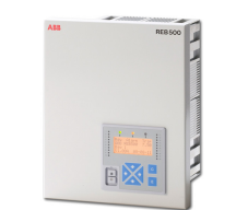
Fig. 5 Bay unit
Central unit (500CU03)
The hardware structure is based on standard
racks and only a few different module types
for the central unit (see Fig. 4).
The modules actually installed in a particular
protection scheme depend on the size, complexity and functionality of the busbar system.
A parallel bus on a front-plate motherboard
establishes the interconnections between the
modules in a rack. The modules are inserted
from the rear.
The central unit is the system manager, i.e. it
configures the system, contains the busbar
replica, assigns bays within the system, manages the sets of operating parameters, acts as
process bus controller, assures synchronization of the system and controls communication with the station control system.
The variables for the busbar protection function are derived dynamically from the process
data provided by the bay units.
The process data are transferred to the central processor via a star coupler module. Up to
10 bay units can be connected to the first central processor and 10 to the others. Central
processors and star coupler modules are
added for protection systems that include
more than 10 bay units. In the case of more
than 30 bay units, additional casings are
required for accommodating the additional
central processors and star coupler modules
required.
All modules of the central unit have a plugand-play functionality in order to minimize
module configuration.
One or two binary I/O modules can be connected to a central processing unit.
The central unit comprises a local HMI with 20
programmable LEDs (Fig. 6), a TCP/IP port
for very fast HMI500 connection within the
local area network.
Distributed busbar protection REB500
including line and transformer protection
Page 9
Functionality Busbar protection
The protection algorithms are based on two
well-proven measuring principles which have
been applied successfully in earlier ABB lowimpedance busbar protection systems:
• a stabilized differential current measurement
• the determination of the phase relationship
between the feeder currents (phase comparison)
The algorithms process complex current vectors which are obtained by Fourier analysis
and only contain the fundamental frequency
component. Any DC component and harmonics are suppressed.
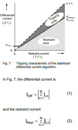
The first measuring principle uses a stabilized
differential current algorithm.
The currents are evaluated individually for
each of the phases and each section of busbar (protection zone).
where N is the number of feeders. The following two conditions have to be accomplished
for the detection of an internal fault:
where
kst stabilizing factor
kst max stabilization factor limit.
A typical value is kst max = 0.80
IK min differential current pick-up value
The above calculations and evaluations are
performed by the central unit.
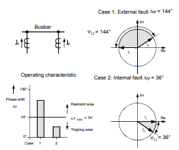
The second measuring principle determines
the direction of energy flow and involves comparing the phases of the currents of all the
feeders connected to a busbar section.
The fundamental frequency current phasors
1..n (5) are compared. In the case of an internal fault, all of the feeder currents have almost the same phase angle, while in normal
operation or during an external fault at least
one current is approximately 180° out of
phase with the others
The algorithm detects an internal fault when
the difference between the phase angles of all
the feeder currents lies within the tripping
angle of the phase comparator (see Fig. 8).
Distributed busbar protection REB500
including line and transformer protection
The task of processing the algorithms is
shared between the bay units and the central
processing unit. Each of the bay units continuously monitors the currents of its own fee-der,
preprocesses them accordingly and then filters the resulting data according to a Fourier
function. The analog data filtered in this way
are then transferred at regular intervals to the
central processing unit running the busbar
protection algorithms.
Depending on the phase-angle of the fault,
the tripping time varies at Idiff/Ikmin5 between 20 and 30 ms including the auxiliary
tripping relay.
Optionally, the tripping signal can be interlocked by a current or voltage release criteria
in the bay unit that enables tripping only when
a current above a certain minimum is flowing,
respectively the voltage is below a certain
value.
Breaker failure protection
The breaker failure functions in the bay units
monitor both phase currents and neutral current independently of the busbar protection.
They have two timers with individual settings.
Operation of the breaker failure function is
enabled either:
• internally by the busbar protection algorithm (and, if configured, also by the internal line protection, overcurrent or pole
discrepancy protection features) of the bay
level
• externally via a binary input, e.g. by the line
protection, transformer protection etc.
After the delay of the first timer has expired, a
tripping command can be applied to a second
tripping coil on the circuit-breaker and a
remote tripping signal transmitted to the station at the opposite end of the line.
This first timer operates in a stand-alone
mode in the bay unit.
If the fault still persists at the end of the second time delay, the breaker failure function
uses the busbar replica to trip all the other
feeders supplying the same section of busbar
via their bay units.
A remote tripping signal can be configured in
the software to be transmitted after the first or
second timer.
Phase-segregated measurements in each bay
unit cope with evolving faults.
End fault protection
In order to protect the “dead zone” between
an open circuit-breaker and the associated
CTs, a signal derived from the breaker position and the close command is applied.
The end fault protection is enabled a certain
time after the circuit-breaker has been opened. In the event of a short circuit in the dead
zone the nearest circuit-breakers are tripped.
This function is performed in a stand-alone
mode in the bay unit.
Overcurrent function
A definite time overcurrent back-up protection
scheme can be integrated in each bay unit.
(The operation of the function, if para-meterized, may start the local breaker failure protection scheme).
This function is performed in a stand-alone
mode in the bay unit.
Current release criteria
The current release criteria is only performed
in the bay unit. It is effective for a busbar protection trip and for an intertripping signal
(including end fault and breaker failure) and
prevents those feeders from being tripped that
are conducting currents lower than the setting
of the current release criteria.
Voltage release criteria
The voltage criterion is measured in the bay
unit. The function can be configured as
release criterion per zone through internal
linking in the central unit. This necessitates
the existence of one set of voltage transformers per zone in one of the bay units. Tripping
Distributed busbar protection REB500
including line and transformer protection
is only possible if the voltage falls short of
(U<) or exceeds (U0>) the set value.
Additionally this release criterion can be configured for each feeder (voltage transformers
must be installed). For details see Table 22.
Check zone criterion
The check zone algorithm can be used as a
release criterion for the zone-discriminating
low-impedance busbar protection system. It is
based on a stabilized differential current measurement, which only acquires the feeder currents of the complete busbar. The isolator /
breaker positions are not relevant for this criterion.
Neutral current detection I0
Earth fault currents in impedance-grounded
systems may be too low for the stabilized differential current and phase comparison functions to detect. A function for detecting the
neutral current is therefore also available, but
only for single phase-to-earth faults.
Pole discrepancy
A pole discrepancy protection algorithm
supervises that all three poles of a circuitbreakers open within a given time.
This function monitors the discrepancy between the three-phase currents of the circuitbreaker.
When it picks up, the function does not send
an intertripping signal to the central unit, but, if
configured, it starts the local breaker failure
protection (BFP logic 3).
This function is also performed in a standalone mode in the bay unit.
Event recording
The events are recorded in each bay unit. A
time stamp with a resolution of 1ms is attached to every binary event. Events are divided
into the three following groups:
• system events
• protection events
• test events
The events are stored locally in the bay unit or
in the central unit.
Disturbance recording
This function registers the currents and the
binary inputs and outputs in each bay. Voltages can also be optionally registered (see
Table 14).
A disturbance record can be triggered by
either the leading or lagging edges of all
binary signals or by events generated by the
internal protection algorithms. Up to 10 general-purpose binary inputs may be configured
to enable external signals to trigger a disturbance record. In addition, there is a binary
input in the central and the bay unit for starting
the disturbance recorders of all bay units.
The number of analog channels that can be
recorded, the sampling rate and the recording
period are given in Table 14. A lower sampling
rate enables a longer period to be recorded.
The total recording period can be divided into
a maximum of 15 recording intervals per bay
unit.
Each bay unit can record a maximum of 32
binary signals, 12 of which can be configured
as trigger signals.
The function can be configured to record the
pre-disturbance and post-disturbance states
of the signals.
The user can also determine whether the recorded data is retained or overwritten by the
next disturbance (FIFO = First In, First Out).
This function is performed in a stand-alone
mode in the bay unit (see page 7).
Note:
Stored disturbance data can be transferred via
the central unit to other computer systems for
evaluation by programs such as PSM505 [3].
Files are transferred in the COMTRADE format.
After retrieving the disturbance recorder data,
it is possible to display them graphically with
PSM505 directly.
Communication interface
Where the busbar protection has to communicate with a station automation system (SAS),
a communication module is added to the central unit. The module supports the interbay
bus protocols IEC 61850-8-1, IEC 60870-5-
103 and LON.
The IEC 61850-8-1 interbay bus transfers via
either optical or electrical connection:
• differential current of each protection zone
• monitoring information from REB500 central unit and bay units
• binary events (signals, trips and diagnostic)
• trip reset command
Distributed busbar protection REB500
including line and transformer protection
• disturbance recording data (via MMS file
transfer protocol)
• time synchronization with Simple Network
Time Protocol (SNTP)
• two independent time servers are supported. Server 2 as backup time
The LON interbay bus transfers via optical
connection:
• differential currents of each protection zone
• binary events (signals, trips and diagnostic)
• trip reset command
• disturbance recording data (via HMI500)
• time synchronization
The IEC 60870-5-103 interbay bus transfers
via either optical or electrical connection:
• time synchronization
• selected events listed in the public part
• all binary events assigned to a private part
• all binary events in the generic part
• trip reset command
Test generator
The HMI program (HMI500) which runs on a
PC connected to either a bay unit or the central processing unit includes a test generator.
During commissioning and system maintenance, the test generator function enables the
user to:
• activate binary input and output signals
• monitor system response.
• test the trip circuit up to and including the
circuit-breaker
• test the reclosure cycles
• establish and perform test sequences with
virtual currents and voltages for the bay
protection of the REB500sys
The test sequencer enables easy testing of
the bay protection without the need to decommission the busbar protection. Up to seven
se-quences per test stage can be started. The
sequences can be saved and reactivated for
future tests.
Isolator supervision
The isolator replica is a software feature without any mechanical switching elements. The
software replica logic determines dynamically
the boundaries of the protected busbar zones
(protection zones). The system monitors any
inconsistencies of the binary input circuits
connected to the isolator auxiliary contacts
and generates an alarm after a set time delay.
In the event of an isolator alarm, it is possible
to select the behavior of the busbar protection:
• blocked
• zone-selective blocked
• remain in operation
Differential current supervision
The differential current is permanently supervised. Any differential current triggers a timedelayed alarm. In the event of a differential
current alarm, it is possible to select the
behavior of the busbar protection:
• blocked
• zone-selective blocked
• remain in operation
Trip redirection
A binary input channel can be provided to
which the external signal monitoring the circuit-breaker air pressure is connected. Tripping is not possible without active signal.
When it is inactive, a trip generated by the
respective bay unit is automatically redirected
to the station at the opposite end of the line
and also to the intertripping logic to trip all the
circuit-breakers connected to the same section of busbar.
The trip redirection can also be configured
with a current criterion (current release criteria).
Distributed busbar protection REB500
including line and transformer protection
Page 13
Human machine interface (HMI)
The busbar protection is configured and maintained with the aid of human machine interfaces at three levels.
Local HMI
The local display interface installed in the central unit and in the bay units comprises:
• a four-line LCD with 16 characters each for
displaying system data and error messages
• keys for entering and display as well as 3
LEDs for the display of trips, alarms and
normal operation.
• in addition 20 freely programmable LEDs
for user-specific displays on the bay unit
500BU03 and central unit 500CU03.
The following information can be displayed:
• measured input currents and voltages
• measured differential currents (for the busbar protection)
• system status, alarms
• switchgear and isolator positions (within
the busbar protection function)
• starting and tripping signals of protection
functions
External HMI (HMI500)
More comprehensive and convenient control
is provided by the external HMI software running on a PC connected to an optical interface
on the front of either the central unit or a bay
unit. The optical interface is completely
immune to electrical interference. The PC
software facilitates configuration of the entire
busbar protection, the set-ting of parameters
and full functional checking and testing. The
HMI500 can also be operated via the LON
Bus on MicroSCADA for example, thus eliminating a separate serial connection to the central unit.
The HMI runs under MS WINDOWS NT, WINDOWS 98, WINDOWS 2000 and WINDOWS
XP. The HMI500 is equipped with a comfortable on-line help function. A data base comparison function enables a detailed
comparison between two configuration files
(e.g. between the PC and the central unit or
between two files on the PC).
Remote HMI
A second serial interface at the rear of the
central unit provides facility for connecting a
PC remotely via either an optical fiber, TCP/IP
or modem link. The operation and function of
HMI500 is the same whether the PC is connected locally or remotely.
Additional
functionalities
Bay level functions
These functions are based on the well established and well-proven functions built in the
ABB line and transformer protection. The bay
level functions contain all the relevant additional functions, which are normally requested
of a line and transformer protection scheme.
The line protection functions (L-V1 - L-V7) are
used as Main 2 or back-up for lines as well as
for transformer bays. The transformer protection functions (T-V1 - T-V4) are used as Group
2 or back-up bay protection for transformer
bays or as an independent T-Zone protection.
Distributed busbar protection REB500
including line and transformer protection
High-speed distance protection
• Overcurrent or underimpedance starters
with polygonal characteristic
• Five distance zones (polygon for forwards
and reverse measurement)
• Load-compensated measurement
• Definite time overcurrent back-up protection (short-zone protection)
• System logic
- switch-onto-fault
- overreach zone
• Voltage transformer circuit supervision
• Power swing blocking function
• HF teleprotection. The carrier-aided
schemes include:
- permissive underreaching transfer tripping
- permissive overreaching transfer tripping
- blocking scheme with echo and transient blocking functions
• Load-compensated measurement
- fixed reactance slope
- reactance slope dependent on load
value and direction (ZHV<)
• Parallel line compensation
• Phase-selective tripping for single and
three-pole autoreclosure
• Four independent, user-selectable setting
groups.
In the supervision mode the active and reactive power with the respective energy direction
is displayed by the HMI500.
Autoreclosure
The autoreclosure function permits up to four
three-phase autoreclosure cycles. The first
cycle can be single phase or three-phase.
If the REB500sys autoreclosure function is
employed, it can be used as a back-up for the
autoreclosure realized externally (separate
equipment or in the Main 1 protection).
When the autoreclosure function is realized
outside of REB500sys, all input and output
signals required by the external autoreclosure
equipment are available in order to guarantee
correct functionality.
Synchrocheck
The synchrocheck function determines the difference between the amplitudes, phase
angles and frequencies of two voltage vectors. The synchrocheck function also contains
checks for dead line and dead bus.
Transformer differential protection
• For two- and three-winding transformers
• Auto transformers
• Three-phase function
• Current-adaptive characteristic
• High stability for external faults and current
transformer saturation
• No auxiliary transformers necessary
because of vector group and CT ratio compensation
• Inrush restraint using 2nd harmonic
The transformer differential protection function
can also be used as an autonomous T-zone
protection in a 1½ breaker scheme.
Thermal overload
This function protects the insulation against
thermal stress. This protection function is normally equipped with two independently set
levels and is used when oil overtemperature
detectors are not installed.
Peak value over- and undercurrent protection
These functions are used for current monitoring with instantaneous response and where
insensitivity to frequency is required.
Peak value over- and undervoltage protection
This function is used for voltage monitoring
with instantaneous response and where insensitivity to frequency is required.
Frequency function
The function is used either as an over-/ underfrequency protection, or for load-shedding in
the event of an overload. Several stages of
the frequency protection are often needed.
This can be achieved by configuring the frequency function several times.
Rate of change frequency protection df/dt
This function is used for the static, dynamic
and adaptive load-shedding in power utilities
and industrial distribution systems. The function supervises the rate-of-change df/dt of one
voltage input channel. Several stages of the
rate-of-change frequency protection are often
Distributed busbar protection REB500
including line and transformer protection
Page 15
needed. This can be achieved by configuring
the rate-of-change frequency function several
times.
Definite time overfluxing protection
This function is primarily intended to protect
the iron cores of transformers against excessive flux. The function works with a definite
time delay. The magnetic flux is not measured
directly. Instead the voltage/frequency-ratio,
which is proportional to the flux is monitored.
Inverse time overfluxing protection
This function is primarily intended to protect
the iron cores of transformer against excessive flux. The function works with an inverse
time delay. The inverse curve ca be set by a
table of 10 values and the times t-min and tmax. The magnetic flux is not measured directly. Instead the voltage/frequency-ratio,
which is proportional to the flux is monitored.
Power function
This function provides single, or three phase
measurement of the real or apparent power.
The function can be configured for monitoring
reverse, active or reactive power (power
direction setting). Phase angle errors of the
CT/VT inputs can be compensated by setting.
The operating mode can be configured either
to underpower or to overpower protection.
Logics and delay/integrator
These functions allow the user the engineering of some easily programmable logical functions and are available as standard also in the
REB500 functionality.
Directional sensitive earth fault protection
for grounded systems
A sensitive directional ground fault function
based on the measurement of neutral current
and voltage is provided for the detection of
high-resistance ground faults in solidly or lowresistance grounded systems. The scheme
operates either in a permissive or blocking
mode and can be used in conjunction with an
inverse time earth fault overcurrent function.
In both cases the neutral current and voltage
can be derived either externally or internally.
This function works either with the same communication channel as the distance protection
scheme or with an independent channel.
Directional sensitive earth fault protection
for ungrounded or compensated systems
The sensitive earth fault protection function for
ungrounded systems and compensated systems with Petersen coils can be set for either
forwards or reverse measurement. The characteristic angle is set to ±90°
(U0 · I0 · sin ) in ungrounded systems and to
0° or 180° (U0 · I0 · cos ) for systems with
Petersen coils. The neutral current is always
used for measurement in the case of systems
with Petersen coils, but in ungrounded systems its use is determined by the value of the
capacitive current and measurement is performed by a measuring CT to achieve the
required sensitivity. To perform this function
the BU03 with 3I, 1MT and 5U is required.
Definite time over- and undercurrent protection
This function is used as Main 2 or as back-up
function respectively for line, transformer or
bus-tie bays. This function can be activated in
the phase- and/or the neutral current circuit.
Inverse time overcurrent protection
The operating time of the inverse time overcurrent function reduces as the fault current
increases and it can therefore achieve shorter
operating times for fault locations closer to the
source. Four different characteristics according to British Standard 142 designated normal
inverse, very inverse, extremely inverse and
long time inverse but with an extended setting
range are provided. The function can be configured for single phase measurement or a
combined three-phase measurement with
detection of the highest phase current.
Inverse time earth fault overcurrent protection
The inverse time earth fault overcurrent function monitors the neutral current of the system. Four different characteristics according
to British Standard 142 designated normal
inverse, very inverse, extremely inverse and
long time inverse but with an extended setting
range are provided.
Directional overcurrent definite / inverse
time protection
The directional overcurrent definite time function is available either with inverse time or definite time overcurrent characteristic. This
function comprises a voltage memory for
faults close to the relay location. The function
response after the memory time has elapsed
can be selected (trip or block).
Definite time over- and undervoltage protection
This function works with a definite time delay
with either single or three-phase measurement.
Distributed busbar protection REB500
including line and transformer protection
Additional functionalities (cont’d)
Three-phase current plausibility
This function is used for checking the sum and
the phase sequence of the three-phase currents.
Three-phase voltage plausibility
This function is used for checking the sum and
the phase sequence of the three-phase voltages.
Additional
features
Self-supervision
All the system functions are continuously
monitored to ensure the maximum reliability
and availability of the protection. In the event
of a failure, incorrect response or inconsistency, the corresponding action is taken to
establish a safe status, an alarm is given and
an event is registered for subsequent diagnostic analysis.
Important items of hardware (e.g. auxiliary
supplies, A/D converters and main and program memories) are subjected to various
tests when the system is switched on and also
during operation. A watchdog continuously
monitors the integrity of the software functions
and the exchange of data via the process bus
is also continuously supervised.
The processing of tripping commands is one
of the most important functions from the reliability and dependability point of view. Accordingly, every output channel comprises two
redundant commands, which have to be
enabled at regular intervals by a watchdog. If
the watchdog condition is not satisfied, the
channels are blocked.
Extension of the system
The system functions are determined by software, configured using the software configuration tool.
The system can be completely engineered in
advance to correspond to the final state of the
station. The software modules for new bays or
features can be activated using the HMI500
when the primary plant is installed or the features are needed.
Additional system functions, e.g. breaker failure, end fault protection or bay level
back-up / Main 2 functions can be easily activated at any time without extra hardware.
Resetting the trip commands/-signals
The following resetting modes can be selected for each binary output (tripping or signal
outputs):
• Latches until manually reset
• Resets automatically after a delay
Inspection/maintenance
A binary input is provided that excludes a bay
unit from evaluation by the protection system.
It is used while performing maintenance
respectively inspection activities on the primary equipment.
Redundant power supplies (Option)
Two power supply modules can be fitted in a
redundant arrangement, e.g. to facilitate
maintenance of station batteries. This is an
option for the central unit as well as for the
bay unit.
Time synchronization
The absolute time accuracy with respect to an
external time reference depends on the
method of synchronization used:
• no external time synchronization:
accuracy approx. 1 min. per month
• periodic time telegram with minute pulse
(radio or satellite clock or station control
system): accuracy typically ±10 ms
• periodic time telegram as above with second pulse: accuracy typically ±1 ms
• a direct connection of a GPS or DCF77 to
the central unit is possible: accuracy typically ±1 ms
• Furthermore, the time synchronization can
be done, if available, via the interbay bus
IEC103, LON or SNTP (in case IEC61850-
8-1 is used)
The system time may also be synchronized by
a minute pulse applied to a binary input on the
central unit.
Distributed busbar protection REB500
including line and transformer protection
Page 17
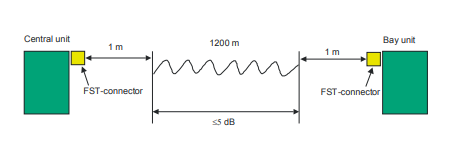
Requirements Optical fiber cables
A distributed busbar protection layout requires optical fiber cables and connectors with
the following characteristics:
• 2 optical fiber cores per bay unit
• glass fibers with gradient index
• diameter of core and sheath 62.5,
respectively 125 m
• maximum permissible attenuation 5 dB
• FST connector (for 62.5 m optical fibers)
• rodent protected and longitudinally waterproof if in cable ducts
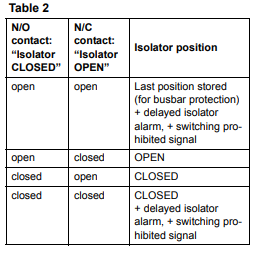
Isolator auxiliary contact
Auxiliary contacts on the isolators are connected to binary inputs on the bay units and
control the status of the busbar replica in the
numerical busbar protection.
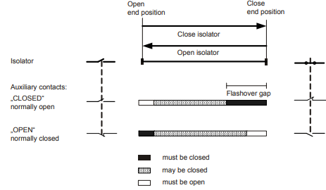
One potentially-free N/O and N/C contact are
required on each isolator. The N/O contact
signals that the isolator is “CLOSED” and the
N/C contact that the isolator is “OPEN”. During the closing movement, the N/O contact
must close before the isolator main contact
gap reaches its flashover point.
Conversely, during the opening movement,
the N/O contact must not open before the isolator main contact gap exceeds its flashover
point.
If this is not the case, i.e. the contact signals
‘no longer closed’ beforehand, then the N/C
contact may not signal “OPEN” before the
flashover point has been exceeded.
Distributed busbar protection REB500
including line and transformer protection
Circuit-breaker replica
When the circuit-breaker replica is read in the
feeder or the bus-tie breaker, the circuitbreaker CLOSE command must also be connected.
Main current transformer
The algorithms and stabilization features used
make the busbar protection largely insensitive
to CT saturation phenomena. Main CTs types
TPS (B.S. class x), TPX, TPY, 5P.. or 10P.. are
permissible.
TPX, TPY and TPZ CTs may be mixed within
one substation in phase-fault schemes. The
relatively low CT performance needed for the
busbar protection makes it possible for it to
share protection cores with other protection
devices.
Current transformer requirements for stability during external faults (Busbar protection)
The minimum CT requirements for 3-phase
systems are determined by the maximum fault
current.
The effective accuracy limit factor (n') must be
checked to ensure the stability of the busbar
protection during external faults.
The rated accuracy limit factor is given by the
CT manufacturer. Taking account of the burden and the CT losses, the effective accuracy
limit factor n' becomes:
where:
n = rated accuracy limit factor
PN = rated CT power
PE = CT losses
PB = burden at rated current
In the case of schemes with phase-by-phase
measurement, n' must satisfy the following
two relationships:
where:
IKmax = max. primary through-fault current
I1N = rated primary CT current
Taking the DC time constant of the feeder into
account, the effective n' becomes:
(2) n' 10 for TN 120 ms, or
n' 20 for 120 ms <TN 300 ms.
where:
TN = DC time constant
Example: IKmax = 30000 A
I1N = 1000 A
TN 120 ms
Applying relationships (1) and (2):
(2) n' 10
Selected: n' 10
The current transformer requirements for
REB500sys for Line and Transformer protection are described in a separate publication
[1].
Pick-up for internal faults
In the case of internal busbar faults, CT saturation is less likely, because each CT only
conducts the current of its own feeder.
Should nevertheless CT saturation be possible, it is important to check that the minimum
fault current exceeds the setting for Ikmin.
Note:
For systems that measure I0, the REB500
questionnaire 1MRB520371-Ken should be
filled in and submitted to ABB, so that the CT
requirements can be checked in order to
ensure proper I0 measurement.
-
 Hirschmann RS20-1600M2T1SDAEHH03.1.02 Rail Switch
 -
 Hirschmann BRS30-24TX Industrial Rail Switch
 -
 Hirschmann RSPM20-4T14T1EV9HHS999.9.99 Managed Ethernet Switch
 -
 Hirschmann BELDEN RS40-0009CCCCSDAPHH09.0.14 / RS400009CCCCSDAPHH09014
 -
Hirschmann RS40 Rail Switch RS40-0009CCCCSDAE
-
 Hirschmann BELDEN RS30-0802T1T1SDAP / RS300802T1T1SDAP Fully Managed Layer 2 Compact Rail Switch
 -
 Hirschmann BELDEN RS20-0800M2M2SDAUHH / RS200800M2M2SDAUHH
 -
 Hirschmann EAGLE30-04022O6TT999SCCY9HSE3F Industrial Firewall Router Switch
 -
 Hirschmann RS20-1600T1T1SDAEHH09.0.14 RS20 Rail Mount Ethernet Switch
 -
 Hirschmann EAGLE0200T1T1TDDY90000HHE05.3.03 Industrial Security Router
 -
Hirschmann - BELDEN MIPP-AD-1L9P
-
 HIRSCHMANN RSPM20-4Z64Z6TV9HHS9 942 106-999 RAIL SAFETY SWITCH
 -
 HIRSCHMANN FIBEROPTIC MODULE FIP P/N: OZDFIPG3T
 -
 HIRSCHMANN RS20-1600M2M2SDAUHH Ethernet rack-mounted switch
 -
 HIRSCHMANN BELDEN RS20-0400T1T1SDAEHH04.0.01 / RS200400T1T1SDAEHH04001
 -
HIRSCHMANN MM2-4FXM3 MICE Media Module
-
HIRSCHMANN RS20-0800M2M2SDAE Industrial Ethernet Rail Switch
-
 Hirschmann RS20-2400T1T1SDAP / RS20-2400T1T1SDAPHH05.0.02
 -
 GE MLJ1005B010H00C MLJ Digital Synchromism Check
 -
 ALSTOM MICROTECH DX21-M2 Digital Excitation Controller
 -
HIRSCHMANN BRS20-1200ZZZZ-STCY99HHSES
-
 HIRSCHMANN MM3-4FXM2 MICE Media Module
 -
Hirschmann RSB20-0800T1T1SAABHH 8Port ENet Rail Switch RSB20
-
 Hirschmann MACH102-8TP Ethernet Switch
 -
 SAACKE DDZ-M marine steam pressure atomizer
 -
 SAACKE SKV-A marine rotary cup atomizer
 -
 SAACKE Seavis HMI05e
 -
 Kollmorgen MMC-SD-2.0-230 Servo Drive 100-240VAC 2KW 10A Output 3PH 100-240VAC
 -
 Kollmorgen Servo drive CR10550
 -
 Kollmorgen AKD-P01207-NACN-0054 Servo Driver
 -
 Kollmorgen S406M-CA-036 Servostar
 -
.png) Kollmorgen AKD-B02407-NAAN-0000 Digital Servo Drive
Kollmorgen AKD-B02407-NAAN-0000 Digital Servo Drive -
 Kollmorgen SERVOSTAR S406AM-CA Digital Servo Drive
 -
 KOLLMORGEN SERVOSTAR 603-AS SERVO AMPLIFIER_SERVOSTAR603AS_S60301
 -
Kollmorgen S700 Servo Controller (S70602-NANANA-NA)
-
 Kollmorgen MPK411 controller
 -
 KOLLMORGEN MMC-SD-1.3-460-D Smart Drive
 -
 KOLLMORGEN AKM21C-CKB2AA-00 / AKM21CCKB2AA00 Servomotor
 -
 BECKHOFF AX5106-0000-0200 | Digital Compact Servo Drives 1-channel
 -
 BECKHOFF C3620-0000 INDUSTRIAL COMPUTER (MOTORSHELVES)
 -
 Beckhoff EK1960-0000 TwinSAFE Compact Controller
 -
 Beckhoff C6930-0050 Control Cabinet Industrial PC
 -
 Beckhoff CP7711-0001-0030 Industrial Computer Detection
 -
 Beckhoff CX1001-0111 Embedded PC CPU Module
 -
 Beckhoff C6017-0020 | Ultra-compact Industrial PC
 -
 Beckhoff EK1322 | 2-port EtherCAT P junction with feed-in
 -
 Beckhoff CP2219-0010 Panel
 -
 BECKHOFF C6015-0020 ULTRA COMPACT INDUSTRIAL PC
 -
 BECKHOFF CX2030-0120/Standard CPU Module Embedded PC Windows PLC controller
 -
 Beckhoff CP7721-1090-0020 Panel PC
 -
 Beckhoff PC CPU Module CX5130-0175
 -
 Beckhoff C6920-0050 Control Cabinet
 -
 Beckhoff EL6631 EtherCAT 2-Port Communication Interface, Profinet RT Controller
 -
 Beckhoff CP6202-0001-0060 touch screen panel PC
 -
 Beckhoff CP3916-1002-0000 Multi-Touch Control Panel
 -
 Beckhoff EP1809-0021 | EtherCAT Box, 16-channel digital input, 24 V DC, 3 ms, M8Preferred type
 -
 Beckhoff CX8190 PLC Embedded Industrial PC Ethernet Controller
 -
 Beckhoff CX2100-0914 Power Supply for External
 -
 Beckhoff Automation CP6906-0001-0000 HMI
 -
 Beckhoff EP7342-0002 Module
 -
 Beckhoff CX1020-0112 / CX1100-0910 / CX1020-N010 / CX1100-0003 Windows CPU
 -
 Beckhoff EP7211-0034 EtherCAT Box 1 Channel Motion Interface
 -
 Beckhoff C6240-0030 Control cabinet Industrial PC
 -
 beckhoff motherboard CB1052-0004 CB1052-0004
 -
 Beckhoff AX2006-AS Servo Drive / Variable Frequency Drive
 -
BECKHOFF CP6207-0001-0020 NSMP
-
 Beckhoff C6930-1142-0060 Industrial Computer
 -
 Beckhoff FC7501-0000 interface card
 -
 Beckhoff CX5140-0175 Embedded PC PLC CPU CX5140 Industrial Controller
 -
 Beckhoff CP7802-1100-0010: High-End IP65 Control Panel with DVI/USB Extended Interface
 -
BECKHOFF CP3716-1058-0010 CONTROL PANEL
-
 Beckhoff AX8108-0000 Single-Axis Module
 -
 Beckhoff CU8851-0000 | USB extension, USB Extended 2.0 receiver box
 -
Beckhoff C6017-0030 | Ultra-compact Industrial PC
-
 Beckhoff CX1001-0120/CX10010120.cx1000-n001.cx1000-n000 System Overview
 -
 Beckhoff CPU Module CX5140-0155/4GB CPU Module
 -
 Beckhoff CP6533-0001-005: Built-in Panel PC with High-Definition Multi-Touch Control
 -
 Beckhoff EL5042 | EtherCAT Terminal, 2-channel encoder interface, BiSS® C
 -
 Beckhoff C6920-1080-0040: Premium Control Cabinet Industrial PC
 -
 Beckhoff C6920-0060 | Control cabinet Industrial PC
 -
 Beckhoff Embedded-PC CX5010-1121
 -
 Beckhoff CB3050-0010 Mainboard Motherboard
 -
 Beckhoff PLC module CX1020-0000 Basic CPU module (service phase)
 -
 Beckhoff CP7812-1056-0010 15" Multitouch Display Control Panel
 -
 Beckhoff CX5120-0115 /2GB Controller Module
 -
 Beckhoff CP7201-1000-0000 Industrial Panel PC
 -
 Beckhoff Servo Motor AM8061-0JH1-0000
 -
 BECKHOFF CP6503-0001-0050 Built-in Panel PC
 -
Beckhoff CP3919-0010 Display G190ETN01.2 19" PCT V04. Multi-touch Control Panel
-
 Beckhoff CX5110-0112-9020/000368201 Embedded PC Intel Atom Processor
 -
 Beckhoff AX8206-0000 Dual-Axis Module
 -
Beckhoff Nail Operating Terminal CP7032-1031-0010
-
Beckhoff AM8042-0EH1-0000 Servomotor 4.10 Nm (M0), F4 (87 mm)
-
 Beckhoff EK9300 Beckhoff CPU Module
 -
Beckhoff CP3224-0020 Multitouch-Panel-PC
-
 Beckhoff CP2712-0000 12.1" 24VDC Touch Screen WMD0
 -
 BECKHOFF CX5240-0195 / 0000289234 Embedded PC 40 GB CFast Card
 -
 Beckhoff CP6932-1000-0000 Control Panel
 -
 BECKHOFF CX5120-0121 PLC Module
 -
 Beckhoff EL3218 | EtherCAT Terminal, 8-channel analog input
 -
Beckhoff C6640-0050 | Control cabinet Industrial PC
-
 Beckhoff Cx5130-0120/4GB Embedded-PC
 -
 BECKHOFF CX2030-0122 PLC PROCESSOR
 -
 BECKHOFF CX5020-0122 Controller Module
 -
 Beckhoff CP3915-0000 Multitouch Panel
 -
 BECKHOFF EL3014 | EtherCAT Terminal
 -
 BECKHOFF Industrial Computer c6920-1057-0030
 -
 Beckhoff CX5130-0141/4GB CX5130-0141 Embedded PC
 -
 Beckhoff C6240-1052-0040 4-086-06-3073 Industrial Computer
 -
 Beckhoff CX5140-0135 /4GB High-Performance Embedded Industrial PC
 -
 Beckhoff C6515-1001-0000 Industrial PC
 -
 Beckhoff AX5103-0000-0200 - Digital Compact Servo Drives
 -
 Beckhoff CX2030-0130-1003/4GB Basic CPU module
 -
 Beckhoff AX8620-0000 Power Supply Module
 -
 Beckhoff CX9020-0111 module with
 -
 Beckhoff EL7332 PLC Module
 -
 BECKHOFF CP7709-0001-0020 HMI
 -
 Beckhoff CX5120-0155/2GB Embedded PC
 -
 BECKHOFF CP7037-1037-0010 OPERATOR INTERFACE TOUCHSCREEN
 -
 Beckhoff EK9000 | ModbusTCP/UDP Bus Coupler
 -
 Beckhoff Touch Panel Screen CP6020 -0000-0000
 -
 Beckhoff CX2020-0121 Module FAST Shipping
 -
 Beckhoff CX2030-0125 Basic CPU Module
 -
 Beckhoff CP3918-0000 Multi-Touch 18.5" Control Panel
 -
 Automotion LC4A00010 DC BL Motor Control, ATS, Sub Assy, SCP, 115VAC,
 -
 500T-115VAC - VAS ENGINEERING - DORIC 500 SERIES DIGITAL TEMP INDICATOR
 -
 Honeywell X-DCS2000/EN Digital Integrated System Manager 50/60Hz 100-240V #4
 -
 Kollmorgen S60600 Servostar600 606-Fan 4 kVA, 6 A, 3 X 230 - 480 V


