
FOXBORO FBM201e Analog Input (0 to 20 mA) Interface Modules
FOXBORO FBM201e Analog Input (0 to 20 mA) Interface Modules
The FBM201e Analog Input Interface Module provides eight dc current input channels.
FEATURES
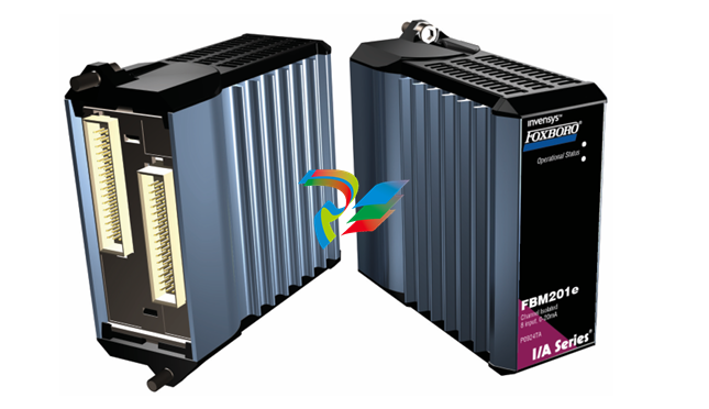
Key features of the FBM201e module are:
Eight 0 to 20 mA dc channels for input of analog
sensor signals
Each analog input channel is galvanically isolated
from other channels and ground
Compact, rugged design suitable for enclosure in
Class G3 (harsh) environments
Execution of an analog input application program
that provides conversion time and configurable
options for integration time and Rate of Change
Limits
High accuracy achieved by sigma-delta data
conversions for each channel
Termination Assemblies (TAs) for locally or
remotely connecting field wiring to the FBM201e
Termination Assemblies for per channel internally
and/or externally loop powered transmitters.
OVERVIEW
Each FBM201e Analog Input Interface Module
contains eight analog input channels, each channel
accepting a 2-wire, dc input from an analog sensor
such as a 4 to 20 mA transmitter
The modules perform the signal conversion required
to interface the electrical input signals from the field
sensors to the optionally redundant fieldbus.
COMPACT DESIGN
The FBM201e module has a compact design, with a
rugged extruded aluminum exterior for physical
protection of the circuits. Enclosures specially
designed for mounting the FBMs provide various
levels of environmental protection, up to harsh
environments per ISA Standard S71.04.
HIGH ACCURACY
For high accuracy, the module incorporates sigma
delta data conversion on a per-channel basis, which
can provide a new analog input reading every 25 ms,
and a configurable integration period to remove any
process noise and power-line frequency noise.
Each time period, the FBM converts each analog
input to a digital value, averages these values over
the time period, and provides the averaged value to
the controller.
EASY REMOVAL/REPLACEMENT
The module can be removed/replaced without
removing field device termination cabling, power or
communications cabling.
VISUAL INDICATORS
Light-emitting diodes (LEDs) incorporated into the
front of the modules provide visual status indications
of Fieldbus Module (FBM) functions.
MODULAR BASEPLATE MOUNTING
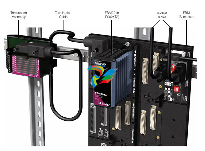
The module mounts on a modular baseplate (see
Figure 1) which accommodates up to four or eight
FBMs. The modular baseplate is either DIN rail
mounted or rack mounted, and includes signal
connectors for redundant fieldbus, redundant
independent dc power, and termination cables.
FIELDBUS COMMUNICATION
A Fieldbus Communication Module or a Control
Processor interfaces the redundant 2 Mbps module
Fieldbus used by the FBMs. The FBM201e module
accepts communication from either path (A or B) of
the redundant 2 Mbps fieldbus – should one path fail
or be disabled at the system level, the module
continues communication over the active path.
TERMINATION ASSEMBLIES
Field I/O signals connect to the FBM subsystem via
DIN rail mounted TAs (see Figure 1). The TAs used
with the FBM201e module are described in
“TERMINATION ASSEMBLIES AND CABLES” on
page 7
FUNCTIONAL SPECIFICATIONS
Process I/O Communications
Communicates with its associated FCM or FCP via
the redundant 2 Mbps module Fieldbus.
Input Channels
8 isolated and independent channels
Input Range (each channel)
0 to 20 mA dc
Input Channels (8)
ANALOG ACCURACY (INCLUDES LINEARITY)
±0.02% of span
Accuracy temperature coefficient: ±50 ppm/ºC
FIELD DEVICE CABLING DISTANCE
Maximum distance of the field device from the
FBM is a function of compliance voltage @20 mA
(21.4 V dc), wire resistance, and voltage drop at
the field device.
Input Channel Isolation
Each channel is galvanically isolated from all other
channels and earth (ground). The module/TA
withstands, without damage, a potential of 600 V ac
applied for one minute between any channel and
ground, or between a given channel and any other
channel.
WARNING
This does not imply that these channels are
intended for permanent connection to
voltages of these levels. Exceeding the limits
for input voltages, as stated elsewhere in this
specification, violates electrical safety codes
and may expose users to electric shock.
Power Requirements
INPUT VOLTAGE RANGE (REDUNDANT)
INPUT CHANNEL IMPEDANCE
61.5 Ω nominal
INPUT SIGNAL A/D CONVERSION
Each channel performs A/D signal conversion
using an independent Sigma-Delta converter.
INTEGRATION PERIOD
Software configurable.
COMMON MODE REJECTION
>100 db at 50 or 60 Hz
NORMAL MODE REJECTION
>95 db at 50 or 60 Hz
LOOP SUPPLY
24 V dc ±2.5%
OUTPUT IMPEDANCE
68 Ω
LOOP POWER SUPPLY PROTECTION
Each channel is channel-to-channel galvanically
isolated, current limited, and voltage regulated.
All analog inputs are limited by their design to less
than 30 mA. If the current limit circuit shorted out,
the current is limited to about 100mA.
24 V dc +5%, -10%
CONSUMPTION
7 W (maximum)
HEAT DISSIPATION
3 W (maximum)
Calibration Requirements
Calibration of the module and termination assembly is
not required
FUNCTIONAL SPECIFICATIONS (CONTINUED)
Regulatory Compliance
ELECTROMAGNETIC COMPATIBILITY (EMC)
European EMC Directive 89/336/EEC
Meets: EN 50081-2 Emission standard
EN 50082-2 Immunity standard
EN 61326 Annex A (Industrial
Levels)
CISPR 11. Industrial Scientific and Medical
(ISM) Radio-frequency Equipment -
Electromagnetic Disturbance Characteristics - Limits and Methods of Measurement
Meets Class A Limits
IEC 61000-4-2 ESD Immunity
Contact 4 kV, air 8 kV
IEC 61000-4-3 Radiated Field Immunity
10 V/m at 80 to 1000 MHz
IEC 61000-4-4 Electrical Fast
Transient/Burst Immunity
2 kV on I/O, dc power and communication
lines
IEC 61000-4-5 Surge Immunity
2kV on ac and dc power lines; 1kV on I/O
and communications lines
IEC 61000-4-6 Immunity to Conducted
Disturbances Induced by Radio frequency
Fields
10 V (rms) at 150 kHz to 80 MHz on I/O,
dc power and communication lines
IEC 61000-4-8 Power Frequency Magnetic
Field Immunity
30 A/m at 50 and 60 Hz
PRODUCT SAFETY
Underwriters Laboratories (UL) for U.S. and
Canada
UL/UL-C listed as suitable for use in
UL/UL-C listed Class I, Groups A-D;
Division 2; temperature code T4 enclosure
based systems. These modules are also UL
and UL-C listed as associated apparatus for
supplying non-incendive communication
circuits for Class I, Groups A-D hazardous
locations when connected to specified
I/A Series® processor modules as described
in the I/A Series DIN Rail Mounted
Subsystem User’s Guide (B0400FA).
Communications circuits also meet the
requirements for Class 2 as defined in
Article 725 of the National Electrical Code
(NFPA No.70) and Section 16 of the
Canadian Electrical Code (CSA C22.1).
Conditions for use are as specified in the
I/A Series DIN Rail Mounted Subsystem
User’s Guide (B0400FA).
European Low Voltage Directive 73/23/EEC
and Explosive Atmospheres (ATEX) directive
94/9/EC
CENELEC (DEMKO) certified as
EEx nA [nL] IIC T4 for use in CENELEC
certified Zone 2 enclosure certified as
associated apparatus for supplying non
incendive field circuits for Zone 2. Group IIC,
potentially explosive atmospheres when
connected to specified I/A Series processor
modules as described in the I/A Series DIN
Rail Mounted Subsystem User’s Guide
(B0400FA). Also, see Table 1 on page 8
ENVIRONMENTAL SPECIFICATIONS(1)
Operating
TEMPERATURE
FBM201e-20 to +70°C (-4 to +158°F)
Termination Assembly-20 to +70°C (-4 to +158°F)
RELATIVE HUMIDITY
5 to 95% (noncondensing)
ALTITUDE-300 to +3.000 m (-1.000 to +10.000 ft)
Storage
TEMPERATURE-40 to +70°C (-40 to +158°F)
Mounting
FBM201e
The module mounts on a modular baseplate. The
baseplate can be mounted on a DIN rail
(horizontally or vertically), or horizontally on a
19-inch rack using a mounting kit. Refer to DIN
Rail Mounted Modular Baseplates (PSS 21H
2W6 B4) for details.
TERMINATION ASSEMBLY
The TA mounts on a DIN rail and accommodates
multiple DIN rail styles including 32 mm (1.26 in)
and 35 mm 1.38 in).
Mass
FBM201e
284 g (10 oz) approximate
TERMINATION ASSEMBLY
Compression
181 g (0.40 lb) approximate
Ring Lug
249 g (0.55 lb) approximate
RELATIVE HUMIDITY
5 to 95% (noncondensing).
ALTITUDE-300 to +12.000 m (-1.000 to +40.000 ft)
Contamination
Suitable for use in Class G3 (Harsh) environments as
defined in ISA Standard S71.04. based on exposure
testing according to EIA Standard 364-65. Class III.
Vibration
7.5 m/S2 (0.75 g) from 5 to 500 Hz
PHYSICAL SPECIFICATIONS
Dimensions – FBM201e
HEIGHT
102 mm (4 in)
114 mm (4.5 in) with mounting lugs
WIDTH
45 mm (1.75 in)
DEPTH
104 mm (4.11 in)
Dimensions – Termination Assembly
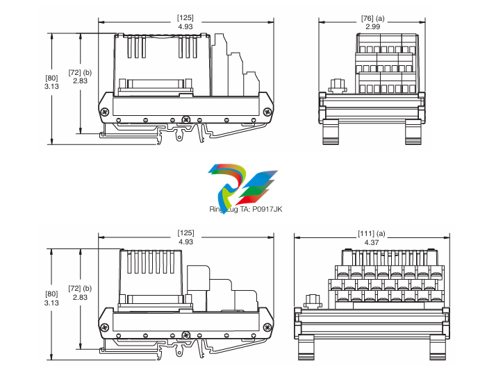
See page 10
Part Number
FBM201e
P0924TA
TERMINATION ASSEMBLIES
See “FUNCTIONAL SPECIFICATIONS –
TERMINATION ASSEMBLIES” on page 8
PHYSICAL SPECIFICATIONS (CONTINUED)
Termination Cables
CABLE LENGTHS
Up to 30 m (98 ft)
CABLE MATERIALS
Hypalon®/XLP
TERMINATION CABLE TYPE
Type 1 – See Table 2 on page 9
BASEPLATE TO MAIN TA CABLE CONNECTION
FBM Baseplate End
37-pin D-subminiature
Termination Assembly End
25-pin D-subminiature
Construction – Termination Assembly
MATERIAL
Polyamide (PA), compression
PA, ring lug
TERMINATION ASSEMBLIES AND CABLES
Field input signals connect to the FBM subsystem via
DIN rail mounted Termination Assemblies, which are
electrically passive (see Figure 1). TAs for the
FBM201e module are available in the following forms:
Compression screw type using Polyamide (PA)
material
Ring lug type using Polyamide (PA) material
See “FUNCTIONAL SPECIFICATIONS –
TERMINATION ASSEMBLIES” on page 8 for a list of
TAs used with the FBM201e module.
Field Termination Connections
COMPRESSION-TYPE ACCEPTED WIRING
SIZES
Solid/Stranded/AWG
0.2 to 4 mm2/0.2 to 2.5 mm2/24 to 12 AWG
Stranded with Ferrules
0.2 to 2.5 mm2 with or without plastic collar
RING-LUG TYPE ACCEPTED WIRING SIZES
#6 size connectors (0.375 in (9.5 mm))
0.5 to 4 mm2/22 AWG to 12 AWG
A removable termination cable connects the DIN rail
mounted TA to the FBM via a field connector on the
baseplate in which the FBM is installed. Termination
cables are available in Hypalon® XLP.
Termination cables are available in a variety of
lengths, up to 30 meters (98 feet), allowing the
Termination Assembly to be mounted in either the
enclosure or in an adjacent enclosure. See Table 2
for a list of termination cables used with the TAs for
the FBM201e module
-
 CTI 2559-TC 8-Channel Thermocouple Input Module
 -
 CTI 2556-A 16-Channel Isolated Thermocouple Input Module
 -
 CTI 2556 16-Channel Isolated Thermocouple Input Module
 -
 CTI 2551-A 8-Channel Isolated Thermocouple Input Module
 -
 CTI 2559-RTD 8-Channel RTD Input Module
 -
 CTI 2557-A 16-Channel RTD Input Module
 -
 CTI 2557 16-Channel RTD Input Module
 -
 CTI 2552-A 8-Channel Isolated RTD Input Module
 -
 CTI 2534 8-Point Form-C Relay Output Module
 -
 CTI 2532 16-Point Form-A Relay Output Module
 -
 CTI 2531 32-Point Form-A Relay Output Module
 -
 CTI 2530 8-Point Form-C Relay Output Module
 -
 CTI 2562 8-Channel Analog Output Module
 -
 CTI 2560-A 8-Channel Isolated Analog Output Module
 -
 CTI 2501 8in/4out Analog Module
 -
 CTI 2558 8-Channel Analog Input Module
 -
 CTI 2555-A 16-Channel Analog Input Module
 -
 CTI 2550-A 8-Channel Isolated Analog Input Module
 -
 CTI 2599 8/16/32-Point AC Output Module
 -
 CTI 2598-8 8-Point AC Output Module
 -
 CTI 2598 8/16-Point AC Output Module
 -
 CTI 2597 8/16/32-Point DC Output Module
 -
 CTI 2596-8 8-Point DC Output Module
 -
 CTI 2596 8/16-Point DC Output Module
 -
 CTI 2595 16-Point TTL/Word Output Module
 -
 CTI 2591-EF 16-Point Isolated 11-146 VDC Output with Front Panel Accessible Fuses
 -
 CTI 2591-A 16-Point Isolated 11-146 VDC Output Module
 -
 CTI 2590-EF 16-Point Isolated 20-132 VAC Output with Front Panel Accessible Fuses
 -
 CTI 2590-A 16-Point Isolated Discrete 20-132 VAC Output Module
 -
 CTI 2589-B 8/16/32-Point Universal Discrete Input Module
 -
 CTI 2589-A 8/16/32-Point Universal Discrete Input Module
 -
 CTI 2588-8 8-Point Universal Discrete Input Module
 -
 CTI 2585 16-Point TTL/Word Input Module
 -
 CTI 2582 16-Point Isolated 125 VDC Input Module
 -
 CTI 2581 16-Point Isolated 12-56 VDC Input Module
 -
 CTI 2580 16-Point Isolated 95-132 VAC Input Module
 -
 CTI 2500-TAP RS485 Network Tap
 -
 CTI 2500-RIO-B RS485 Remote Base Controller
 -
 CTI 2500-RIO-A RS485 Remote Base Controller
 -
 CTI 2500-RBC Profibus Remote Base Controller
 -
 CTI 2515-A 100-Watt AC/DC Power Supply with Redundancy Support
 -
 CTI 2515 100-Watt AC Power Supply (MATURE - replaced by 2515-A)
 -
 CTI 2513-A 75-Watt DC Power Supply with Redundancy Support
 -
 CTI 2513 75-Watt 24VDC Power Supply
 -
 CTI 2512-A 75-Watt AC/DC Power Supply with Redundancy Support
 -
 CTI 2512 75-Watt AC/DC Power Supply
 -
 CTI 2510 125 VDC Power Supply
 -
 CTI 2500-SSB Single Slot Blank Front Panel
 -
 CTI 2500-R11-A Eleven-Slot Redundant Base
 -
 CTI 2500P-R16 Sixteen-Slot Base with High-Speed Channel
 -
 CTI 2500P-R8 Eight-Slot Base with High-Speed Channel
 -
 CTI 2500P-R4 Four-Slot Base with High-Speed Channel
 -
 CTI 2541 Redundant Processor Manager Module
 -
 CTI 2577 Profibus DP Slave Adapter
 -
 CTI 2573-MOD Serial Interface Adapter with MODBUS
 -
 CTI 2572-AF Fast Ethernet TCP/IP Adapter with Optical Fiber Connection
 -
 CTI 2572-A Fast Ethernet TCP/IP Adapter
 -
 CTI 2572 Ethernet TCP/IP Adapter
 -
 CTI 2572-B Fast Ethernet TCP/IP Adapter
 -
 CTI 2576 DeviceNet™ Scanner Module (MATURE)
 -
 CTI 2500P-ECC1 Ethernet Communications Coprocessor
 -
 CTI 2500P-JACP Janus Application Coprocessor
 -
 CTI 2500P-ACP1 Application Coprocessor (MATURE - replaced by 2500P-JACP)
 -
 CTI 2500P-J450 Janus PAC with 2MB Project Memory
 -
 CTI 2500-C400 CPU with 3072K User Memory
 -
 CTI 2500-C300 CPU with 512K User Memory
 -
 CTI 2500-C200 CPU with 256K User Memory
 -
 CTI 2500-C100 CPU with 128K User Memory
 -
 CTI 2500P-J750 Janus PAC with 3MB Project Memory
 -
 Shinkawa WHF3006M Displacement Converter
 -
Shinkawa JBP-220 (P-24-94A / P-24-94B) Circuit Board Module
-
 SHINKAWA WKN-142K5 2-WIRE VIBRATION TRANSDUCER
 -
Shinkawa FRP-321 (P-26-54A / P-26-54B) Circuit Board Module
-
 Shinkawa IOP-160 (P-25-72A / P-25-72B) Circuit Board Module
 -
 Shinkawa PK-147B-1 / PK-147A-1 Circuit Board Module
 -
 Shinkawa CPP-91A Circuit Board Module
 -
 Shinkawa FRP-177 PCB Module
 -
 Shinkawa CPP-127 (P-26-74A / P-26-74B) Circuit Board Module
 -
Shinkawa FRP-227 (P-24-86A / P-24-86B) Circuit Board Module
-
 Shinkawa MDP-104 (P-25-83A / P-25-83B) Circuit Board Controller
 -
 Shinkawa VK-143P2 High-precision eddy current sensor driver/signal conditioner
 -
 Shinkawa FRP-226 (P-24-86A / P-24-86B) Circuit Board Module
 -
Shinkawa CPP-107A P-22-99A P-22-99B Circuit Board Module
-
 SHINKAWA VW-202AL-8 Axial Displacement Sensor
 -
Shinkawa VL-202A08L-1A42 Vibration Sensor Transducer Probe
-
Shinkawa VL-202A08L-1A42 Vibration Sensor Transducer Probe
-
 Shinkawa FRP-209A & FRP-206 Wire Bonder Circuit Board Module
 -
 Shinkawa MGP-72 MGP72 P-26-50A P-26-50B Circuit Board Module
 -
 Shinkawa FRP-249 P-25-1A P-25-1B Circuit Board Module
 -
Shinkawa FRP-320 P-26-54A P-26-54B Circuit Board Module
-
Shinkawa FRP-282 P-24-35A P-24-35B Circuit Board Module
-
 Shinkawa FRP-338 P-26-54A P-26-54B Circuit Board Module
 -
 GE IS200AEPBH1B IS200AEPBH1B‑REV‑AA Pitch-Charger Control PCB Board
 -
 GE IS200EDEXG1ADA EX2100 SCR Trigger Control Board
 -
 GE 151X1207CK01SA01 IS200EDEXG1A EX2100 SCR
 -
 GE 151X1233DD02SA02 IS200AEPBH1B - Variant for pitch control charger assembly
 -
 GE 151X1233DB01SA01 IS200AEPBH1B - 10kW Wind Power Converter
 -
 GE 151X1233DB01SA01R | IS200AEPBH1B 10KW Converter
 -
GE 151X1233DD01SA02 Pitch Battery Charger (109W6931P001)
-
GE 151X1233DD01SA02 Pitch Battery Charger Assy IS200AEPBH1B
-
 GE 151X1233DB02SA02 Rev A IS200AEPBH1B Wind Turbine Converter
 -
 GE 151X1207CK02SA02 SCR 4400 V 1850 A IS200EDEXG1ADA General Electric EX2100
 -
 Triconex 3723X 32-Channel TMR Analog Input Module with HART
 -
 SHINKAWA VM-21G SIGNAL CONDITIONER SOCKET
 -
SHINKAWA VM-21R REVOLUTION SIGNAL CONDITIONER
-
SHINKAWA VM-21T DISPLACEMENT INPUT THRUST SIGNAL CONDITIONER
-
SHINKAWA VM-21D 6-WIRE LVDT SIGNAL CONDITIONER
-
 SHINKAWA VM-21P 3-WIRE LVDT SIGNAL CONDITIONER
 -
SHINKAWA VM-21A VIBRATION SIGNAL CONDITIONER
-
SHINKAWA VM-21K DISPLACEMENT INPUT VIBRATION SIGNAL CONDITIONER
-
 SHINKAWA VM-25S01 CONDITION MONITORING SYSTEM
 -
SHINKAWA VM-25 CONDITION MONITORING SYSTEM
-
SHINKAWA VM-772B DEVICE CONFIG
-
SHINKAWA VM-771B MCL VIEW
-
 SHINKAWA VM-76B INSTRUMENT RACK
 -
SHINKAWA VM-75B POWER SUPPLY MODULE
-
 SHINKAWA VM-742B NETWORK COMMUNICATION MODULE
 -
 SHINKAWA VM-741B LOCAL COMMUNICATION & PHASE MARKER MODULE
 -
SHINKAWA VM-722B 9-CHANNEL RELAY MODULE
-
SHINKAWA VM-707B AERODERIVATIVE GAS TURBINE MONITOR MODULE
-
 SHINKAWA VM-706B ROD DROP MONITOR MODULE
 -
 SHINKAWA VM-705B 18-CHANNEL TEMPERATURE MONITOR MODULE
 -
SHINKAWA VM-704B TEMPERATURE MONITOR MODULE
-
 SHINKAWA VM-702B ABSOLUTE VIBRATION MONITOR MODULE
 -
SHINKAWA VM-701B VIBRATION / DISPLACEMENT MONITOR MODULE
-
 SHINKAWA MODEL VM-5X INTERFACE UNIT
 -
 SHINKAWA MODEL VM-5W2 DUAL POWER SUPPLY INSTRUMENT RACK
 -
 SHINKAWA MODEL VM-5H4 INSTRUMENT RACK (for VM-5Z5.6.7)


